Note: Descriptions are shown in the official language in which they were submitted.
2 0 7 ~
PATENT
ON 47684
5RA~E WITH DE~!AC~BLE 8~0E
BACRGROIJND OF THE INVENTION
The present invention relates to skates and more particularly
to skates with detachable shoes.
5Skates designed for attachment to conventional shoes are shown
in the prior art. As an example, u.s. Patent No. 25,295 of
Wheeler discloses an ice skate having an extendable heelpiece for
permitting the insertion of a shoe into a webbed structure with
adjustable straps.
10U.SO Patent No. 1,835,446 of Tracy shows an in-line roller
skate with a toe strap and an ankle strap to hold a shoe on the
flat footplate.
U.S. Patent No. 3,228,707 of Davis et al. shows a roller skate
having a bifurcated pliable, e.g. leather member with an elastic
15insert. The member overlies the shoe from toe to ankle, is
attached at the front and rear of the skate and has an adjustable
strap for tightening the pliable member about the shoe.
U.S. Patent No. 3,829,111 of Nicholls describes an in-line
roller skate having plastic foot straps and a heel enclosure, each
20of which is laced over the shoe.
U.S. Patent No. 3,963,252 of Carlson discloses an in-line
roller skate having a stiff non-rotatable laceable heel enclosure
and a laced plastic foot covering. The heel enclosure and foot
2~7~8~
PATE~T
ON 47684
covering are slidable ~or accommodating different shoe sizes and to
ease mounting of the shoe therein.
U.S. Patent No. ~,993,318 of Rothmayer and U.S, Patent No,
2,168,820 o Edstrom disclose skates having a buckled toe str~p and
5 a non-pivotable heel member having several straps which are bucXled
over the inserted shoe.
u.s. Pa~ent No. 4,072,317 of Pommerening shows an in-line
roller skate in which the ankle bracing support includes a strap
about the lower ankle and a pivotable cradle which extends above
10 the ankle to be strapped to the wearer's leg. A laced strap
extends over the shoe behind the toe portion.
U.s. Patent No. 4,418,929 of Gray shows an in-line skate in
which a shoe is mounted and held on a pair of support plates by a
toe strap and a middle foot strap, both attached by self-adhering
15 means. A leg case encloses the lower leg, i.e. ankle.
U.S. Patent No. 4,708, 352 of Vullierme discloses a roller
skate with a toe plate and a heel plate which are telescopically
extendable relative to each other. An enclosure on the toe plate
substantially covers the foot up to the ankle, and the heel plate
20 has a heel retainer with an adjustably buckled strap which passes
over the user's foot and over a tongue on the toe enclosure.
U.S. Patent No. 4,884,491 of Wheelwright discloses a three
wheeled skate in which a shoe is attached to the skate. A toe
shroud covers the toe of the shoe and presses downward thereon. In
2~713~
PATENT
ON 47684
addition, the shoe heel fits in a slidable heel cup and a pivotable
ankle bracs is strapped about the user's ankle a~ove the shoe.
~ ach of the above indicated prior art di~closures requires a
relatively stiff shoe with relatively inflexible sole, in order to
operate with sufficient long-term com~ort. The soft padded sport
shoes which have recently gained extreme popularity are not readily
accommodated by the prior skates because (a) retaining forces are
concentrated on small areas of the user's foot, causing discomfort,
or (b) the shoe is free to twist and bend within the shoe retainer,
lo leading to less control in operation and an accompanying loss of
safety. In addition, mounting of the shoe in the skate requires
multiple operations to achieve the desired alignment and tension on
the shoe, if such is possible. None of the above listed prior art
skates has met with significant commercial success.
U.S. Patent No. 4,943,075 discloses wheeled skate-skis in
which a pair of wraparound bindings are draped around the skater's
sport shoes and attached to the skate with "Velcro" fasteners.
However, it is known in the art that the retaining strength of such
fasteners is insufficient to accommodate the high forces often
generated in skating movements, particularly when the forces are
exerted in a direction coinciding with the direction of movement
which separates the "Velcro" components.
PCT Publication No. WO 89/03712 of Murga discloses a skate for
use with a sport shoe. The shoe is retained on the skate base by
2~718~
PATENT
ON 47684
a toe strap and a heel enclosure. Extending upwardly from the heel
enclosure and spaced from the shoe is a pivotable leg support which
is attached about the user's leg. The skating forces are
concentrated in a narrow band over the skater's foot and in a ~and
on the leg, rather than being more widely distributed over the
surface of the foot.
The need remains in the art for a commuter skate having a
detachable shoe, the combination of which is stable, comfortable
and safe, and wherein the shoe per se comprises a useful and
aesthetically pleasing sport shoe. There is a further need for
such a combination in which the shoe and skate are joined and
separated by the use of a simply operated buckle~ There is a still
further need for such a sport shoe which is easily attached to the
wearer's foot with minimal effort yet is firmly retained on the
foot. In addition, the need exists for a skate-shoe combination
wherein the toe of the shoe is held rigidly in the skate.
The need further exists for a comfortable and safe commuter
skate which collapses to a reduced size for e.g. carrying in a
portable pack or storage in a locker.
SUMMARY OF THE INVENTION
The invention is a skating apparatus comprising a frame with
a hard shell and skate surface contact element(s), and a
multipurpose shoe which slips into, and is cradled within the
~18~
PATENT
ON 47684
shell. The shoe is configured to be worn either with the frame or
apart from the skating frame as a separate street shoe or sport
shoe, for example. The shell and shoe have interacting features
which (a) guide the shoe into a speci~ic locking position within
th~ shell, (b) firmly lock the shoe ~ole againRt upward toe
movement and lateral sole movement within the shell, yet permit the
wearer~s ankl~s to comfortably pivot forward against a resistance,
(c) provide the desired comfort for extended skating, (d) enable
rapid mounting and dismounting, and (e) provide an attractive shoe
which is comfortable for extended wear for school, work and
sporting purposes. The skate is lightweight and furthermore, the
pivotable cuff assembly may be rotated downwardly to a collapsed
position for portability or storage in limited space.
The shoe is locked to the skate at a given toe position to
enhance control during skating movement. As a result, shoes of
differing sizes, over a limited range, may be used with the same
skate. ThUs, shoes within a four half-size (or two full size)
range may be used while maintaining high performance.
In one configuration, the invention is an in-line skate
particularly useful to students for commuting to school, work, or
other informal events including participation in other sports. The
shoe-skate combination of the invention obviates the need for the
skater to carry additional shoes for off-skate wear. In a
PATENT
ON 47684
preferred configuration, the skating shoe is a padded sport type
shoe with an elastomeric sole.
~ he means ~or effectively guiding and locking the shoe within
the skate includes several features. A slot i~ the front periphery
of the shoe sole interacts with a matching projection in the
concave interior of the toe of the sh~ll. The edge of the sole is
cradled within an enclosing wall of the boot, but is not
necessarily in circumferential contact with the wall. A detent
projecting upwardly from the boot plate ~its into an aperture in
the shoe sole to position the shoe in the same longitudinal
position each time the shoe is inserted. A slanted front wall of
the aperture interacts with the sloped forward edge of the detent
to force the shoe sole forwardly as it is inserted into the boot.
An additional feature which may be incorporated for seating the
sole comprises one or more vertical ramps in the heel portion of
the boot. The ramp(s) force the inserted shoe forwardly to a
position where the detent engages the aperture for final sole
seating. Thus, the forces retaining the forward part of the shoe
on the skate are located in the sole of the shoe rather than
concentrated in a limited area atop the user's foot. Lateral
skating forces generated between skate and shoe are transmitted
from the toe of the sole through the sole to the entire shoe.
A pivotable semirigid cuff extends upwardly from an elevated
heel enclosure, and is lined with padding which adjoins or is
2071806
PATENT
ON 47684
somewhat spaced from the upper edge of the shoe. Thus, when a
strap across the front of the cu~f is closad, the padding prevents
any significant upward movement of the shoe in the boot, locking
the shoe in place. The entire cuff, however, may pivot forward to
accommodate the forward pivoting of the skater's leg in natural
skating motion. Use of a variably adjustable latch permits
adjustment of the resistance to forward pivoting of the skater's
leg.
When the cuff is closed, as by a strap and latch, the front
portion of the cuff interacts downwardly with a semirigid or rigid
outer tongue of the shoe. Thus, stresses between the boot and the
upper of the shoe are distributed by the tongue over an extended
area of the foot. The outer tongue may be formed of a low friction
material to reduce friction between the tongue and cuff assembly
during skating movements.
The hard shell o~ the skate boot also includes a cowl or toe
retainer Which overlies the outside toe area to pro~ide a limit to
upward toe movement during skating, and ~or protection o~ the
user's toes and foot in the event of a spill. The size of the toe
retainer is limited for easy insertion of the shoe in the boot, and
need not extend completely across the foot.
The multi-purpose shoe includes a semirigid or rigid outer
heel enclosure which may be connected to the shoe only at its lower
extremity. During insertion of the shoe into the boot, the
207~8~$
PA~ENT
ON 47684
vertical ramp(s) in the boot heel interact with the rigid shoe heel
to ~orce it forward, as already described. The heel enclosure also
comprises means for comfortably and supportively attaching the shoe
to the skater's foot, and provides protection against heel injury
when the shoe is used in other sports.
The configuration of the boot and shoe ensure interaction to
achieve ease of mounting and dismounting, locXing of the shoe in a
stationary position for high performance skating, comfortable
commuter, recreational or competitive skating, a high safety factor
o and an aesthetically pleasing boot, shoe and combination thereof.
The lightweight, compactible skate is highly portable. The
detached shoe is itself attractive and useful for informal wear and
for sporting activities, obviating the need to carry a separate
pair of shoes when commuting.
BRIEF DESC~IPTION OF ~HE DRAWING8
In the drawings,
FIG. 1 is a lateral perspective view of the combination of a
skate and detachable shoe mounted therein, in accordance with the
invention;
FIG. 2 is a frontal perspective view of the sXate of the
invention;
FIG. 3 is a right side elevational view of a right footed
skate of the invention in the normal skating configuration, minus
the detachable shoe;
2 ~ 6
PATENT
ON 47684
FIG. 4 is a right side elevational view of the right footed
skate, minus the shoe, in a folded transportable configuration;
FIG. 5 is a toe-to-heel vertical cross-sectional view of the
skate and attached shoe along line 5-5 in FIG. 1
5FIG. 6 is a cross-sectional plan view of the skate as taken
along line 6-6 in FIG. 3;
FIG. 7 is a cross-sectional plan view of the skate as taken
along line 7-7 in FIG. 3;
FIG. 8 is an upper right front quarter perspective view of a
10right-footed detachable shoe in accordance with the invention;
FIG. 9 is a lower right front quarter perspective view of a
right-~ooted detachable shoe in accordance with the invention:
FIG. 10 is an elevational, partially cutaway view o~ the
lateral 9ide of a detachable 9hoe in accordance with the invention:
15FIG. 11 is a vertical cross-sectional view o~ the skate of the
invention as taken along line 11-11 in FIG. 2;
FIG. 12 is a graph depicting internal rib angles in an
embodiment of the invention; and
FIG. 13 is an elevational view of the medial side of a
20detachable shoe in accordance with the invention.
DESCRIPTION OF THE ILLUSTRATED EMBODIMENTS
Referring to the drawings, wherein like numerals indicate like
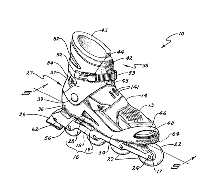
elements, a skating apparatus 10 is illustrated in FIG. 1 and will
2 ~
PAT~NT
ON 47684
be described in combination with FIGS. 2 through 4. The apparatus
10 includes an in-line skate 12 (shown as a right footed skate)
with a detachable ~hoe 14 inserted and locked therein in accordance
with the invention, is shown in FIG. 1. The shoe 14 is depicted in
5the figures as a sport shoe with a generally soft upper 13. The
skate 12 is shown as including a frame 16 which is comprised of a
boot 28, a blade 18 and connecting structure to be further
described in combination with additional figures. Surface contact
means are mounted on blade 18 and may be ground engaging rollers 20
10for roller skating or a narrow elongate linear element useful for
ice skating and well known in the art. The blade 18 is shown with
two parallel, spaced apart blade members 48,49. The surface
contact means is more particularly shown in FIG. 1 as a plurality
of in-line wheels 22 mounted on transverse axles 24 passing through
lSmounting apertures 17 in blade members 48, 49. The skate 12 is
shown with a rear mounted stop or brake pad 26 operated by pivoting
the heel 27 of the skate 12 downward to engage the pad 26 with the
skating surface 60 (FIG. 3). The stop 26 is shown as mounted by a
screw fastener 62 to the blade 18 (FIG. 1).
20A boot or shell 28 is mounted to the blade 18 by intervening
structure including a circumferential wall 19 (FIG. 3) to provide
a nest or cradle into which the detachable shoe 14 is downwardly
and forwardly inserted and affixed for skating. The frame 16
including boot 28, blade 18 and intervening structure may be formed
' i~ 7 ~
PATENT
ON 47684
as a single rigid unit, as by molding of a hard plastic material,
e.g. nylon. The boot 28 has a shoe bed 32 comprising the top
surface of support structure 58 (See FIG~ 2). The shoe bed 32 is
covered with a shoe bed liner 31 (FIGS. 1 and 5) and a shoe-
encircling peripheral wall 34 which extends upwardly from the
lateral wall 19 to generally cradle and girdle the sole 15, FIG. 5,
of shoe 14. The peripheral wall 34 does not generally extend
completely over the shse 14, but is generally open for downward
insertion of the shoe thereinto. The rPar portion of the shoe
girdling wall 34 extends further upwardly to form a generally rigid
heel enclosure 36.
~he means for retaining the shoe 14 in the proper position in
the boot 28 mat include a front elongate rib or projection 64
coincident with the sole 15 of the mounted shoe, and a
corresponding elongate slot 66 in the shoe sole. See FIGS. 5 and
8-10. The projection 64 and slot 66 are arcuate in a generally
horizontal plane, and forces directed forwardly as well as to the
sides are accoD odated without release of the shoe 14.
A padded cuff assembly 38 includes a semirigid cuff 37 and
latch means 44. The cuff 37 is attached by pivot means 39 to each
side of the heel enclosure 36 to pivot about a transverse axis 40
(FIG. 2). The lower rear edge 35 of cuff 37 rests on a
circumferential ridge 33 in the heel enclosure 36 (See FIGS. 3 and
4) to limit the rearward pivoting of the cuff assembly 38 during
11
2 ~
PATE~T
ON 47684
skatlng operat~on~ to the pos~tion shown in FIG. 3 . The cuff 37 is
depicted as including forwardly projecting semi-rigid lateral ~laps
42, 43 which are sufficiently flexible to permit bending inwardly
and outwardly for insertion of the shoe into the skate, and removal
therefrom. The cuff 37 is shown as being lined with a padding
member 45. ~he padding member 45 is attached to the cuff 37 by
eOg. cementing. The lower edge 47 (See FIG. 5) of padding 45 is in
some regions, roughly proximate the upper edge 50 of the shoe 14,
so that upward movement of the user's ankles and the rear portion
of the shoe is limited to prevent disengagement of the shoe 14 from
its locked position in the boot 28. The cuff assembly 38 is
attached to a skater's lower leg by overlapping the cuff flaps 42,
43 and locking adjustable latch 44 at the desired position which
achieves the optimum resistance to forward pivoting of the skater's
leg relative to the skate, and prevents disengagement of shoe 14
from the shell, i.e. boot 28.
A partial cowl or toe retainer 46 is shown as an extension of
the semirigid shoe-encircling wall 34 and overcovers the outer toe
portion of the skater's foot, not shown, within shoe 14. The toe
retainer 46 prevents the toe 48 of the shoe 14 from inadvertently
disengaging outwardly from the boot 28 due to extremely high
tensile forces, as may occur in an accident, and also protects the
wearer's toes from possible abrasion resulting from contact with
the skating surface in such instances.
12
20718~
PATENT
ON 47684
The latch 44 may be any easily operated adjustable
connecting/disconnecting means which firmly joins the two lateral
cu~f flaps 42, 43. The latch 44 has right and left portions 52, 53
attached to the right and left flaps 42,43 respectively of the
cuf f 37, and may include intervening strap portions. An exemplary
latch 44 is shown in the figures as a ratchet buckle. Such ratchet
buckles are typically used for adjustable mounting of alpine ski
boots, well known in the art.
The terms "rigid" and "semirigid" refer to the bending or
flexural properties of the material of construction as well as the
thickness dimensions of the component which contribute to its
rigidity and strength. The frame 16, including the boot 28,
lateral wall 19, internal framework shown in further figures, and
blade 18, together with features to be further defined, are
designed to maintain alignment and rigidity despite high forces
developed during skating movements. In accordance with a preferred
embodiment of the invention, the rigid frame 16, including blade
18, boot 28 and intervening structure may be integrally formed of
a tough plastic material such as nylon having a flexural modulus of
at least about 50 Kpsi and preferably at least 100 Kpsi, as
measured at room temperature and 50% relative humidity (RH). An
exemplary material useful for this application is a nylon material
sold by Dupont with the designation Zytel ST801, and having a
flexural modulus of 125 Kpsi at 23 degrees C and 50~ RH. Other
2~7~ 3~
PATENT
ON 47684
materials may be used which have the requisite long term
strength/flexure characteristics, appearance, cost and ease of
fabrication. The preferred mode of manufacture is injection
molding of the frame in one piece, with subsequent addition of the
surface contact means 20, cuff assem~ly 38, shoe bed liner 31 and
stop member 26.
The thickness of the frame and boot members may typically be
on the order o~ about 1-5 mm, depending on the anticipated local
stresses and the physical properties of the materialts) used. A
minimum of material is used, resulting in a rigid, high strength
but light weight skate. Apertures such as slots 56, 58 may be
formed in the frame 16 for e.g. weight reduction and/or aesthetics.
Means for guiding the shoe into the boot and locking it into
the boot are illustrated in FIGS. 2 through 11.
As shown in FIG. 2, a detent 68 projects upwardly through the
liner 31 to engage an aperture 70 in the sole 15 of shoe 14 (See
FIG. 5). The detent 68 may be formed of several upright planar
members, and has a planar front 72 which is angled upward toward
the rear of the boot. The corresponding aperture 70 has a
similarly angled front wall 74. The angles from the vertical of
front 72 and wall 74 may typically be about 5-35 degrees and
preferably up to about 20 degrees. Thus as the shoe 14 is inserted
downwardly, the detent 68 engages the aperture 70 and forces the
sole 15 forward in the boot.
14
2~71~
PATENT
ON 47684
Also shown in FIGS. 2 and 5-7 is a ramp means 76 in the heel
portion 78 of the boot 28. The ramp means 76 i~ shown as three
narrow ramps or ribs which engage the heel portion of shoe sole 15
to force the sole forward to a po~ition where the de~ent 68 engages
the aperture 70 for subsequent additional ~orward movement o~ the
sole.
The shoe bed 32 may be sized with sufficient space to
accommodate a range of shoe sizes. For example, shoe sizes over a
range of e.g. four half-sizes may be used with the same skate 12.
The separation between the front slot 66 and the detent aperture
70 is then the same, regardless of shoe size within the given
range.
Turning now to a particular feature illustrated in FIGS. 3 and
4, the skate 12 is shown after removal of the shoe 14, to be
collapsible to a reduced size for enhanced portability and storage.
Thus, the cuff assembly 38 may be forwardly and downwardly pivoted
from its normal skating configuration (FIG. 3) to a
carrying/storage configuration of FIG. 4. The cuff is rotated
forwardly through an angle 80 of at least 70 degrees, and may be
rotated up to 100 degrees or more, depending on the material and
construction of the padded cuff assembly 38.
The cuff 37 is formed of a material which permits the lateral
flaps 42, 43 to be bent outwardly during attachment and detachment
of the shoe to the skate, and for collapsing the cuff assembly 38
2~71~
PATENT
ON 47684
to a storage position. While the cuff rigidity should be less than
the rigidity of the skate frame, its flexural modulus must not be
so low that inadequate leg support occurs. The cuff 37 is
typically formed of a material ha~ing a flexural modulus lower than
5 that used for the frame to permit flexing o~ the flaps 42.
Polyurethane or other materials which withstand repeated ~lexure
may be used. ~he cuff 37 may include apertures such as aperture
82, 84 for weight reduction and aesthetic considerations.
As shown in FIGS. 5, 7 and 11, the frame structure provides
high strength and rigidity to the skate with a minimum of material.
The bifurcated blade 18 comprises left and right parallel blade
members 49, 48 which are spaced apart for rotatable attachment of
the ground contact wheels 22. The blade members include upward
extensions thereof, designated 89, 88 in FIG. 11, which have upper
surfaces designated as a shoe bed 32. As shown in FIG. 7,
transverse ribs 90, 92, 94, 96, 98, 100, and 102 are also part of
the shoe bed 32 and provide reinforcement structure to support the
shoe. The generally transverse ribs are integrally formed in the
spaces between blade member extensions 88, 89 and corresponding
lateral walls 19. The ribs may be configured to be parallel to the
highest compressive forces, i.e. vertical. In a preferred
embodiment, however, the ribs are sloped. Each of the ribs 90-102
has a front face and a rear face. Thus, rib 102 is shown with
front face or surface 104 and rear face or surface 106. In this
16
2~7~8~
PATENT
ON 47684
embodiment, the angles o~ the rib faces are important to
man~facture of the frame structure as a single unit. In this
method, the ~rame is formed by injection molding on a last. The
shoe bed 32 is removed from the last by a separating action
beginning at the rear o~ the shoe bed. As the line of separation
moved ~orward toward the toe end, the angle of separation is tilted
toward the rear. Rapid and precise separation occurs when the
front ri~ surfaces of the ribs are at a rearward angle Q from the
vertical such that:
Q - 10 + (X15)/7 +/- 10 ,
where Q is the rearward angle of the front face of the rib, in
degrees from the vertical, and X is the distance in cm. of the
upper surface of the rib from the heel end of the foot bed.
The rear faces of the ribs may be similarly angled, but
preferably are configured to have an angle Q of 1-10 degrees less
than the front faces.
The relationship between Q and X for the front faces of the
transverse ribs 90-102 is illustrated in FIG. 12.
As shown in FIG. 7, the upper edge 110 of transverse rib 100
is not parallel to the other transverse ribs. Use of the non-
parallel rib 100 in the region where the ball of the skater's foot
impinges results in added support and resistance to transverse
17
~f~7~80~
PATENT
ON 47684
bending forces acting on the skate. The result of the footbed
substructure as described above is a very lightweight skate which
has high rigidity, high strength and consistent blade alignment.
As further shown in FIG. 7, a continuous transverse web 112
spans the space between the blade members 48, 49 from the toe end
to the heel end. The web is varlably oriented between the blade
members 48, 49 to provide wheel wells therebetween with adequate
clearance for wheel rotation.
The detachable shoe 14 is depicted in ~IGS . 1, 5, and 8-lo as
lo a sport/casual shoe having a generally soft upper 13 and a
relatively flexible sole 15. The upper 13 is shown as being
formed of panels of differing materials as desired, and may include
both padded and unpadded fabrics, leather, plastic, etc. The
illustrated version of the detachable shoe has suede leather panels
124, 126, 128, 130, 132 and 134 which are generally sewn together.
The figures show a mesh panel 136, and an internal boot 138 of soft
padded fabric. A rigid or semirigid external tongue 140 is
attached to panel 130 and may flex forwardly for insertion of the
wearer's foot. The tongue 140 encases the front of the wearer's
ankle and distributes downwardly directed forces over the ankle.
Thus, the shoe 14 is locked in~o the skate 12 by overlapping the
cuff flaps 42 and 43 (FIGS 1 and 2) and connecting the latch 44.
The flaps 42 and 43 overlie the tongue 140 to absorb upwardly
directed forces from the ska~er's foot. The tongue 140 is
18
207180~
PATENT
ON 47684
prefera~ly formed of a low-friction plastic material such as nylon.
The flexibility of tongue 140 may be controlled by varying the
material of construction, the tongue thickness, or by the use of
slot(s) or other aperture(s) 141 as depicted in FIG. 10.
A rigid or semirigid extern~l heel wrap 142 extends upwardly
from the sole 15 to surround the rear portion of the skater's upper
heel. The heel wrap 142 may be formed of a plastic material such
as nylon or a relati~ely stiff elastomer. The heel w ap 142 is
attached to the sole 15, and may include an opening 143 in the
rear. The heel wrap 142 may include means for restraining a strap
144, shown as a slot 146 in FIG. 13 for guiding the strap. In
addition, as shown in FIGS. 5 and 10, the heel wrap 142 has a strap
retaining recess 149 which preferably is sufficiently deep to
accommodate two overlapped straps, each with a hook-and-loop panel
(FIG. 13) mounted thereon (FIG. 13). The shoe is held firmly on
the wearer's foot by the two straps 144 and 148, both attached to
the shoe 14 on the medial side of the shoe (shown as the right side
of a left shoe in FIG 13). Strap 148 is attached to the sole 15
near or at the heel of the shoe, forward of the external heel wrap
142. Strap 148 passes over the ankle of the wearer, beneath the
tongue 140. Strap 144 is joined to the rear portion of panel 134
for anchorage in the front portion of the shoe 14. Strap 144
extends backward through slot 146 to pass around the upper heel of
the wearer atop the heel wrap 142. Now, looking at the other, i.e.
2~71806
PATENT
ON 47684
lateral side of the shoe in FIGS. 8-10, strap 144 and 148 are
adjustably joined by a connector 150. As shown in FIG. 13, the
~ree end portion 152 of strap 144 has panels 154 and 156 of hook
and loop materials (such as that known as Velcro) so that strap 144
s is doubled back on itself to attach the hook panel to the loop
panel, locking the shoe on the wearer's foot.
As already, described, the shoe sole 15 contains a
circumferential slot 66 in the toe edge 120. The bottom 122 (FIG.
g) of the sole 15 also contains aperture 70 for interacting with
lo dètent 68. The aperture 70 lies behind the ~ront portion o~ the
sole 15, and preferably is in a central portion of the instep or
heel area of the sole, precisely aligned with the detent 68. The
sole 15 is shown as generally formed of an elastomeric material
such as rubber and is circumferentially joined to the upper 13 of
the shoe 14. The sole 15 shown in FIGS. 5 and lo as having a
midsole 158 which is a foam core joined, e.g. cemented, to an upper
core cavity of outsole 162. Midsole 158 is also cemented to the
circumferential bottom portion o~ upper 13. A lasting board 160
and foot bed 161 are shown mounted on the foam midsole. The foot
bed 161 may be removable or non-removable as desired. The outsole
162 is typically formed of solid rubber. This outsole-midsole
combination provides a level of comfort similar to popular sport
and casual shoes.
2 0 ~ 6
PATENT
ON 47684
The combination of skate with detachable shoe is useful for
students and others who frequently commute to school, work or
elsewhere. Thus, for ex~mple, a st`udent may skate to (and from)
school, removing and collapsing the skates, and storing them in a
pack or locker while at school. The detachable shoes 14 may be
comfortably worn to class sessions, in physical sports, and other
non-skating activities, obviating the need to carry one or more
extra pairs of shoes while sXate-commuting. Shoes of varied styles
and colors may be manufactured to provide for differences in
personal tastes.
Reference herein to details of the illustrated embodiments is
not intended to restrict the scope of the appended claims which
themselves recite those features regarded as important to the
invention.
What is claimed:
21