Note: Descriptions are shown in the official language in which they were submitted.
' ~ ' 20'72032
TITLE
"A beverage package"
TECHNICAL FIELD ~ BACRGROUND ART
The present invention relates to a beverage package.
More particularly it concerns beverages containing gas,
such as carbon dioxide and/or nitrogen, in solution and
packaged in a sealed container which, when opened for
dispensing or consumption, causes gas to be evolved or
liberated from the beverage to form, or assist in the
formation of, a head of froth on the beverage. The
beverages to which the invention relates may be alcoholic
or non-alcoholic; primarily the invention was developed
for fermented beverages such as ale, lager, stout or other
beer and cider but may be applied with advantage to so-
called soft drinks and beverages, or alcoholic drinks such
as spirits, liquers, wine and the like.
Beverage packages are known which comprise a sealed
container having a primary chamber containing the beverage
having gas in solution and forming a primary headspace
comprising gas at a pressure greater than atmospheric and
in which a secondary chamber containing gas at a pressure
greater than atmospheric has a restricted orifice which
communicates with the beverage in the primary chamber.
Upon opening the package to dispense the beverage, the
primary headspace is opened to atmospheric pressure and
this creates a pressure differential within the container
which causes gas and/or beverage in the secondary chamber
to be ejected by way of the restricted orifice into the
beverage in the primary chamber. The ejection of the gas
or beverage from the secondary chamber and through the
restricted orifice causes gas in solution in the beverage
to be evolved for froth formation. Examples of beverage
packages having the latter characteristics are disclosed
in
our European Patent Specification No. 0 22? 213 (where
it
is preferred that beverage is ejected from the secondary
2072032
2
chamber for the purposes of froth development) and our
British Patent No. 1,266,351 (where gas is ejected from the
secondary chamber, possibly through a non-return valve, for
the purposes of froth development).
Our aforementioned prior Patents discuss the manner in
which it is believed that gas in solution in the beverage
is caused to be evolved to develop a desirable head of
froth on the beverage by the ejection of gas and/or liquid
from the secondary chamber through the restricted orifice.
This technique for froth development is now well known in
the art.
In the known beverage packages of the kind discussed
above the restricted orifice is located at or towards the
bottom of the beverage in the primary chamber. When the
package is opened and gas and/or liquid/beverage is ejected
through the restricted orifice, gas in solution is
initially evolved in the region of the beverage which is
local to the restricted orifice and this evolution of gas
develops or grows rapidly to rise throughout the volume of
beverage in the primary chamber to develop a head of froth
which is retained when the beverage is dispensed from the
container. For some beverages, particularly those
containing carbon dioxide in solution (with or without
nitrogen gas in solution) it is possible for a major part,
if not all, of the gas in solution to be evolved from the
beverage shortly after the gas or beverage has been ejected
from the secondary chamber on opening the package. As a
consequence, when the beverage is dispensed from the
container into a drinking glass for consumption, it is
possible that the absence, or low level, of gas in solution
in the beverage will impart undesirable characteristics to
the beverage (albeit that such beverage may have a good
quality head of froth). This is particularly the case
for so-called light beers or lagers where it is preferred
that a reasonable volume of gas, usually carbon dioxide, is
' ~0'~ j~3~
3
retained in solution in the beverage as dispensed in a
drinking glass so that such gas can evolve naturally to
rise as minute bubbles within the beverage and the latter
retains a "sparkle" which is considered desirable
aesthetically and can add to the consumer's enjoyment and
"mouth feel" of the beverage. It is an object of the
present invention to provide a beverage package of the
kind
generally discussed and by which the aforementioned
disadvantage of excessive liberation of gas in solution
can
be alleviated so that the beverage when dispensed will
retain a desirable "sparkle" without detracting from the
desirable characteristics required far froth development
in
forming a head on the beverage.
STATEMENT OF INVENTION ~ ADVANTAGES
According to the present invention there is provided
a beverage package comprising a sealed container having
a
primary chamber containing beverage having gas in solution
therewith and forming a primary headspace comprising gas
at
a pressure greater than atmospheric; a secondary chamber
containing gas at a pressure greater than atmospheric and
having a restricted orifice which communicates with an
intermediate chamber containing beverage, said intermediate
chamber opening to the primary chamber at a position remote
from the bottom of the beverage in the primary chamber,
and
wherein said package is openable to open the primary
headspace to atmospheric pressure and said opening creates
a pressure differential causing gas and/or beverage in
the
secondary chamber to be ejected by way of the restricted
orifice into the beverage in the intermediate chamber and
said ejection causes gas in solution to be evolved from
the
beverage in the intermediate chamber for forming froth
in
the primary headspace. Preferably and conveniently the
beverage in the intermediate chamber is derived from the
primary chamber.
Usually each of the secondary and intermediate
' 20'2032
4
chambers will have a volume considerably less than that
of
the primary chamber. The intermediate chamber may
therefore be filled with a relatively small volume of
beverage, conveniently in the form of a column, into which
is injected gas and/or liquid which emanates from the
restricted orifice so that gas in solution in the beverage
in the intermediate chamber is evolved to develop and rise,
through the beverage in the intermediate chamber to form
a
froth in the primary headspace on the beverage in the
l0 primary chamber.
The intermediate chamber may open, at a relatively
high level, into the beverage in the primary chamber.
With this arrangement initial evolution of gas from the
beverage is contained within the intermediate chamber and
this evolution may develop through the beverage in the
intermediate chamber into the beverage in the primary
chamber remote from the bottom of that beverage. As a
consequence, the relatively high energy available from
the
injected gas or beverage can be dissipated, wholly or to
a
substantial extent, through the beverage within the
intermediate chamber and there is relatively little energy
available to effect evolution of the gas from the solution
in the transition through the beverage from that in the
intermediate chamber to that in the primary chamber.
Alternatively the intermediate chamber may open into the
primary headspace above the beverage in the primary
chamber. With this latter arrangement evolution of gas
from the beverage is confined to the beverage in the
intermediate chamber and froth developed from such
evolution and from the beverage in the intermediate chamber
may flow into the primary headspace and be dispensed with
the beverage. By the present invention therefore at least
a desirable proportion of gas, typically carbon dioxide,
can be maintained in solution in a reasonably large
proportion, or the whole, of the volume of the beverage
in
2072032
the primary chamber even though adequate gas may be evolved
for the development of froth as a substantial head.
Therefore when the beverage is dispensed into a glass or
other container, gas can continue to evolve from solution
5 to maintain "sparkle" and other characteristics considered
desirable for the product.
Preferably the restricted orifice is located at or
towards the bottom of the container and the intermediate
chamber extends upwardly from its communication with the
restricted orifice to open into the beverage in the primary
chamber at a required depth beneath the surface of the
beverage in the primary chamber or into the primary
headspace. Desirably the restricted orifice (or two or
more such orifices) is directed downwardly from the
secondary chamber for the ejection of gas or beverage under
pressure from the secondary chamber into the intermediate
chamber to alleviate the possibility of inadvertant excess
beverage flow from the intermediate chamber into the
secondary chamber caused by vibration of the sealed
beverage package during its transportation. It will be
appreciated however that the restricted orifice or orifices
can be located to effect gas and/or beverage injection
sideways or upwardly into the beverage in the intermediate
chamber.
The secondary and intermediate chambers may be built-
in as an integral part of the container. Preferably
however the secondary and intermediate chambers are formed
as an insert that is located in the primary chamber of the
container. Typically this insert will have a hollow part
forming the secondary chamber and a tubular part extending
upwardly from the hollow part, the tubular part forming the
intermediate chamber and having its upper end open to
receive therethrough beverage (usually from the primary
chamber) while the restricted orifice from the secondary
chamber communicates with a lower or the bottom end of the
2o7~o3z
6
intermediate chamber in the tubular part. Conveniently
the insert is formed as a plastics moulding. The insert
will usually be located adjacent to or on a base of the
container within the primary chamber and retained in
position by any convenient means, such as by frictional or
interference engagement with a side wall of the container.
Where the intermediate chamber opens into the primary
headspace it may be necessary to invert and re-invert the
beverage package after sealing to ensure that the
intermediate chamber is adequately charged with beverage
derived from the primary chamber.
DRAWING
Two embodiments of a beverage package constructed in
accordance with the present invention will now be
described, by way of example only, with reference to the
accompanying illustrative drawings in which:
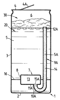
Figure 1 shows a section through the sealed package of
a first embodiment, and
Figure 2 shows a section through the package of the
second embodiment following opening of that package.
DETAILED DESCRIPTION OF DRAWING
The beverage package of each embodiment shown
comprises a conventional form of container such as a light
metal can 1 having a circular base 2 on which the package
will normally stand, a cylindrical side wall 3 and a
circular top 4 which will usually be seamed to the side
wall 3 to seal the container. The top 4 will be openable,
typically by a ring pull or other conventional means for
the purpose of dispensing the beverage. In the present
examples, the can 1 will be regarded as having a capacity
of 500 millilitres.
The sealed can 1 provides a primary chamber 20 within
which is accommodated, say, 440 millilitres of beverage in
the form of a light beer or lager 5 which creates a
headspace 6. Generally the beverage will form a headspace
2072032
7
of 5% to 15% of the capacity of the container {in the
present example the can 1). The beer 5 has in solution
a
mixture of carbon dioxide and nitrogen gases, typically
the
carbon dioxide gas content is 1.75 to 2.50 grams/litre
and
the nitrogen gas content is 3% to 5% vols./vol. The term
"vols./vol" is well known in the art but a definition of
the term may be found in our British Patent No. 1,588,624.
During the formation of the beverage package the headspace
6 is pressurised with nitrogen gas, typically to a pressure
in the range of 1.5 to 3.0 atmospheres. The means for
pressurising the headspace 6 is well known in the art and
is conveniently effected by dosing the headspace with
liquid nitrogen or other inert gas immediately prior to
fitting the top 4 and sealing the container. Located in
the primary chamber 20 is an insert 7 conveniently formed
by plastics moulding.
In the embodiment of Figure 1 the insert 7 is
submerged in the beer 5 and comprises a generally
cylindrical hollow drum 8 which sits with its axis
extending upwardly on or adjacent to the can base 2 and
a
tubular part or chimney 9 which extends upwardly within
the
beer 5. The bottom end 10 of the chimney 9 is sealed to
a top wall 11 of the drum 8 while the top end 12 of the
chimney 9 opens into the beverage 5 in the primary chamber.
The drum 8 forms a secondary chamber 13 while the chimney
9 provides an intermediate chamber 14 which is filled with
beverage 5A derived through the top opening 12 from the
beverage 5 in the primary chamber. Communicating between
the secondary chamber 13 and the intermediate chamber 14
is
a restricted orifice or several such orifices 15 formed
in
the drum wall 11. The secondary chamber 13 contains gas,
usually nitrogen, under pressure which is in equilibrium
with the pressurised headspace 6. The or each restricted
orifice 15 is formed as a circular aperture the diameter
of
which is sufficiently small to alleviate the transfer of
207~0~~
8
gas/beer therethrough (by the surface tension
characteristics of the beer at thr restricted orifice)
while the container is sealed and its contents are in
equilibrium and during vibration or handling to which the
package may reasonably be subjected. It is possible
however that a small volume of beer will seep into the
secondary chamber 13 and lie in the bottom of that chamber
during the initial filling stages of the package and prior
to the contents coming into equilibrium in the sealed
l0 container.
In the present example and typically the secondary
chamber 13 has a volume of 16 millilitres. The chimney
9
has a bore diameter of 6 millimetres and a height of 80
millimetres. Of the 440 millilitres of beer in the
package, approximately 100 millilitres of such beer will
be
accommodated above the level of the chimney opening 12.
Four circular apertures 15 provide communication between
the chambers 13 and 14, each aperture, typically, being
in
the range of 0.03 to 0.23 millimetres diameter.
The insert 7 is conveniently retained with its hollow
drum 8 securely seated on the base 2 by resilient flanges
16 on the drum frictionally engaging with the side wall
3
of the can in known manner.
On opening the top 4 of the can to dispense the beer
5 into a drinking glass far consumption, the headspace
6 is
opened to atmospheric pressure and rapidly depressurises.
As a consequence the pressure of gas in the secondary
chamber 13 exceeds the pressure in the headspace 6 and
creates a pressure differential through the restricted
apertures 15. This causes gas to be ejected from the
chamber 13 through the apertures 15 and injected as high
energy jets into the bottom of the column of beer 5A within
the intermediate chamber 14. This injection of gas is
believed to develop active or nucleation sites in the beer
which causes the gas in solution to evolve. The evolution
207?032
9
of gas is initiated in the bottom end of the beer column 5A
and rapidly grows to rise throughout that column within the
intermediate chamber 14 whilst being contained by the wall
of the chimney 9 from spreading laterally. As the gas
evolution develops and rises through the beer column 5A, it
will eventually spread, with relatively low energy, from
the upper open end 12 of the chimney. This can cause
further evolution of gas from the beer 5 in the primary
chamber 2 which is at a level above the chimney opening 12
and the evolution of gas develops a head of froth on the
beverage 5. As a consequence of the isolating effect
provided by the chimney 9 to localise the beer from which
gas evolution is initiated by the gas injection, a
considerable proportion of the volume of the beer within
the container will retain gas, particularly carbon dioxide,
in solution. Therefore when the beer is poured from the
can 1 into a drinking glass shortly after opening the can,
the froth developed by the evolution of gas from part only
of the beverage may provide a desirable head on the beer in
the glass while adequate gas is maintained in solution in
the beer in the glass for such gas to evolve gradually and
naturally to present a slight effervescent effect or
"sparkle" to the body of the beer - this is considered most
desirable for aesthetic quality in lager or light beer and
may also enhance the flavour characteristics and mouth feel
of the beer.
In the embodiment shown in Figure 2, the insert 7 is
retained by the flanges 16 with its hollow drum 8 submerged
in the beer 5. Similarly to the first embodiment, the
insert 7 includes a generally upstanding tubular part or,
chimney 9A; this chimney 9A however has a U-bend which
permits a lower end 10A of the chimney to be sealed to a
bottom wall 11A of the drum 8. The predominant part
length of the chimney 9A extends upwardly through the beer
5 so that the top end 12A of the chimney opens into the
20??03N
primary headspace 6. The intermediate chamber 14 formed
by the chimney 9A consequently communicates directly with
the primary headspace. Communicating between the
secondary chamber 13 formed by the insert drum 8 and the
5 intermediate chamber 14 are one or more restricted orifices
15A which are formed in the bottom drum wall 11A and are
directed downwardly into the chamber 14. In the sealed
package, the secondary chamber 13 contains gas under
pressure which is in equilibrium with the pressurised
10 headspace 6 while the chimney 9A is charged, usually
filled, with beverage 5A which is preferably and
conveniently derived from the beverage 5 in the primary
chamber 20. To ensure that the intermediate chamber 14 is
appropriately charged with beverage, after the can 1 has
been sealed in an upstanding condition it may be rapidly
inverted immediately following sealing and then re-inverted
to its upstanding condition thereby causing beverage to
flow from the primary chamber 20 into the intermediate
chamber 14 as the fluid contents of the can come into
equilibrium. As the can fluid contents come into
equilibrium it is possible that some beer will flow from
the intermediate chamber 14 into the secondary chamber 13
by way of the restricted orifice 15A to form a secondary
headspace (not shown) in the secondary chamber 13. In
this latter event it may be possible that beverage rather
than gas is initially injected downwardly through the
restricted orifices 15A into the beverage 5A to effect the
evolution of gas from solution fox froth formation. The
various volumes and dimensions of the insert 7 shown in
Figure 2 will be similar to those mentioned for the insert
in Figure 1 except that the chimney 9A will typically have
a diameter in the range of 0.2 to 3.0 mms and will be of
greater length than the chimney 9. Also it is possible
that the restricted orifices 15A can be of relatively large
diameter (typically in the range 0.5 to 2.0 mms) as
207 ? 032
11
compared with the orifices 15 by virtue of the fact that
the orifices 15A are directed downwardly in the beverage
and there is therefore less likelihood that excess beverage
will inadvertently enter the secondary chamber 13 (compared
with the upwardly directed restricted orifices as in Figure
1) during vibration to which the sealed package may be
subjected during its transportation.
When the sealed package of the second embodiment is
opened, for example by a ring pull 4A as shown in Figure 2,
to dispense the beer 5, the headspace 6 is opened to
atmospheric pressure and rapidly de-pressurises.
Similarly to the first described embodiment, this causes
fluid (gas and/or beer) to be ejected from the chamber 13
through the apertures 15A but this ejection is effected
downwardly as high energy jets into the lower end of the
beer 5A within the intermediate chamber 14. Gas in
solution is thereby caused to be evolved from the beverage
5A. The evolution of the gas is initiated in the region
of the beverage 5A adjacent to the end 10A of the chimney
9A but this grows rapidly throughout the beer within the
intermediate chamber 14 but is contained by the wall of the
chimney 9A from spreading laterally. As the upper end 12A
of the chimney 9A is located within the primary headspace
6 the evolution of gas from the beverage is confined to
such beverage 5A as is within the secondary chamber 14.
Therefore froth or foam 30 can develop from the beverage 5A
in the intermediate chamber and the gas which is released
from solution in that beverage 5A. This froth or foam 30
can build-up and spread within the headspace 6 to float on
the surface of the beverage 5 within the primary chamber
and be dispensed along with the beverage 5 as it is poured
from the can. As a consequence of the isolating effect
provided by the chimney 9A to confine the gas evolution to
the beverage within that chimney, all of the beverage 5
within the primary chamber 20 will retain gas, particularly
24'~?032
12
carbon dioxide, in solution. Therefore when the beer is
poured from the can 1 into a drinking vessel, the froth
developed by the evolution of gas from the beer 5A within
the chimney 9A may provide a desirable head on the beer
in
5 the glass while adequate gas is maintained in solution
in
the beer in the glass for such gas to evolve gradually
and
provide the desirable characteristics as previously
discussed.
Although in the above described and illustrated
10 embodiments the restricted orifices 15 and 15A are in
constant communication between the secondary and
intermediate chambers, it will be appreciated that a non-
return valve can be associated with the restricted orifice
to alleviate the seepage of beer into the secondary chamber
15 and be responsive to the previously mentioned pressure
differential that is created on opening of the package
to
open and permit the required gas injection. It is also
envisaged that beer can be ejected from the secondary
chamber by way of the restricted orifice in a similar
20 manner to that disclosed in our European Patent No. 0 227
213 with such beer injection being applied to peer in the
intermediate chamber. It will also be appreciated that
the insert 7 may be structured differently from those
illustrated, for example, the insert 7 shown in Figure
2
25 may have the lower U-bend part length of its chimney 9A
formed integral with the moulding of the drum 8.