Note: Descriptions are shown in the official language in which they were submitted.
w092/~27~ PCT/us~/~1l2
2~72~
-- 1 --
LOAD IMPACT CONTROL~ER
FOR A SPE~D RESULATOR SYS~EM
~ACKGROUND O~ T~E INVENTION
~ield of the Invention
This invention relates to a speed regulator system
- for a d.c. motor, and more specifically to an impact load
s controller or use with a speed controller of such a sy~tem.
De-~criPtion of the Prior Art
In the threading stage of a hot or cold tandem
rolling mill for rolling material, such as a steel strip,
the strip passes through several stands of the mill. The
entry of the strip into the roll bite of the stand causes an
impact load torque to be applied to the drive motors of the
work rolls which are pulling the strip through the roll
bite. When this load is applied to the speed regulator
system, the drlve speed suddenly drops. Any drop in drive
speed of the stand which is being threaded will cause the
strip to gather or buckle between the stand being threaded
and the previou~ stand from which the strip has exited. The
increase in strip storage will result in reduction or loss
in the ten~ion in the ~trip between the two ~tand~ in which
the ~trip i~ be~ng threaded. Thig 103~ in inter~tand
tension ln the strlp i~ a ~erious operational problem for
the ~ill, forcing the mill operator to ~anually operate the
control~ to ~hange the drive speed o the stand or stands
for the threading operation.
This manual operation of the controls sometimes
results in an exce~sive increase in the drive speed and
thus, an excessive removal of strip storage between the
stands, re3ulting in strip breakage.
It i~ not only important that the drive ~peed of
the ~tand in which the strip is being threaded ~peed recover
'': ': '
- ' .' : .
, ~ , .
.~
w092/0827s PCT/US90/~112
- 2 _ 2072~7~ -^
as fast as possible, but al~o to overshoot a safe amount to
quickly remove the strip storage between the stand~ caused
by the speed drop due to the load impact to the drive motor
without cauRing breakage to the strLp.
s Previous attempts may have been made to compensa~e
for thi~ impact load disturbance applied to a speed
regulator drive system of a mill resulting in a speed drop
of the drive ~otor. However, none of these systems have
achieved this compensation in the same manner and with the
same efficiency provided by the present invention.
~he present invention use~ an impact load
controller which operate~ on the rate of change in speed
error to first cause the stand ~peed to overshoot within
safe limits and then to quickly bring this overshoot speed
down to the threading speed or reference speed setting of
the mill.
SUMMARY OF T~E INVENTION
Thi~ invention employs an impact load controller
used with a ~PI) speed controller in a speed regulator
system for a drive motor and is used for compensating for
the speed drop caused by a load disturbance applied to the
motor.
This i~ accompli~hed by providlng an impact load
controller which has a means and a method for determining
the difference between the present speed error and the
previou~ speed error, which ~peed error~ are continually
be~ng updated. Thi~ difference in the speed error values is
mult~plied by "Goose Gain" factor to produce a gain
value. This gain value product i~ initially increased by a
rate factor, which signal i~ initially applied to-a low pass
filter for precharging the low pass filter and to a summer
device for operating the (PI) ~peed controller used in the
speed regulator ~ystem. After a few millisecond~, the gain
-
~ `" ~:';' ` .
' ' :
.
w092~0827S PcT/UssO/06112
~ 3 ~ 2~72~
value product of the impact load controller is changed due,
in part, to the updated value3 of the present speed error
and the previous speed error. The new gain value product
passes directly to the low pass filter. The output from the
s low pass filter i~ combined with the speed error signal and
optionally with an output of a (pI)2 speed controller which
also operates on the speed error ~ignal for an output signal
from a summer device. This output ~rom the summer device is
produced for a desired time period, for example, two ~2)
lo seconds after the strip has entered the roll bite, t~
operate the tPI) speed controller. At this time, the impact
load controller and the (PI)2 speed controller are turned
off, whereby the (PI3 speed controller resumes its normal
operation by operatinq solely on the speed error ~ignal.
This control arrangement for the imp2ct load
controller of the invention may be a digital based
microprocessor or an analog type of control syste~. As
applied to a speed controller for a rolling mill, for
example~ the impact load controller operates on a "strip in
stand" logic signal, and is part of the main logic control
for the mill. The conditions which mu~t be meet for
operation of the loqic system differ for a cold mill'and a
hot mill.
It i~, therefore, a broad ob~ect of the present
invention to provide a means and method for guickly and
ef~lciently compensating for speed drop of a drive motor
cau~ed by an impact load applied to the motor.
It i~ a further object o~ the present invention to
provide a means and method for automatically compensatin~
for speed drop of a drive motor of a mill stand caused by an
impact load when a workpiece initially enters the roll bite
of a ~tand during the threading phase of the ~lll.
-
, '
Wos2/0~2~5 PCT/~S~/~112
_ 4 _ ~072~
It is still a further object of the present
invention to provide a means and method for compensating for
speed drop by rapidly recovering the speed with sufficient
overshoot which does not result in breakage of the
workpiece.
A ~till further object of the present invention is
to provide an impact load controller which may be a
microprocessor or an analog type cont,rol optionally used
with a (pI)2 speed controller, and which impact load
controller i8 operated for only a few seconds after the
workpiece is in the mill stand.
A still further object of the present invention is
to provide a means and method for changing the dynamics of a
(PI) peed controller to reduce the effect of an impact load
disturbance on the response of a speed regulator system.
A still further object of the present invention is
to provide an impact load controller whose output is a
function of the rate of change in the speed error, whereby
this rate of chang~ in speed error is a direct function of
the magnitude of the impact load torque di~turbance applied
to the drive motor, that is, the greater the load, the
greater the output signal of the impaot load controller.
It i~ a still further object of the pre~ent
invention to provide a means and method of producing a
supple~enta} ~ignal which is a function of the rate of
change in speed error and which i~ combined with an error
~ignal and, optionally, with an output s~gnal of a (pI)2
speed controller to control a (PI) speed controller for
regulation of a drive motor.
It i~ a further object of the present invention to
provide an impact load controller which is sel~-adapting to
varying impact loads, thereby providing opt~mum reduction in
the speed error for a drive motor.
' . . . ~ ' ' ' ' - ~ - '
' ~
w092/082~s PCT/US~/~1l2
_ 5 _
2~72071
These and other objects of the present invention
will be more fully understood from the following description
o~ the invention, on reference to the illustration~ appended
thereto.
S ~
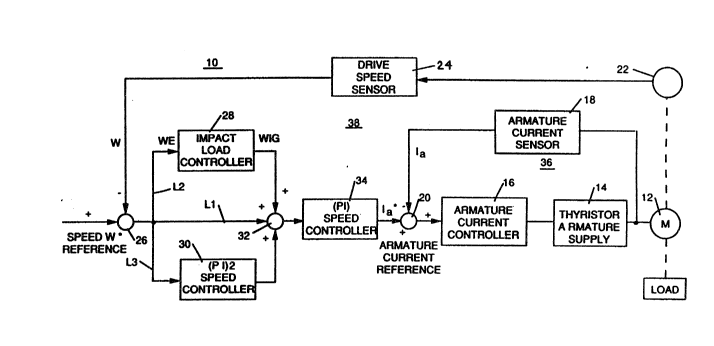
Figure 1 i3 a block diagram of a multiloop speed
regulator system for a drive motor incorporating the present
invention;
Figure 2 i~ a schematic showing of two stands of a
tandem rolling mill illustrating the material storage
problem which is solved by the present invention;
Figure 3 is a detailed block diagram showing the
invention and some of the components of Figure l;
Figure 4 illu3trates the derivation of the rate
dynamic for the transfer function of the impact load
controller of the invention;
Figure~5 show~ a software diagram of the impact
load controller of the present invention;
Figure 6 hows a more detailed block diagram of
the impact load controller of the present invention;
F~gure~ 7A and 7B show a logic diagram for
operating the present invention;
F~gures 8A, 8B, gA, 9B, lOA, lO~ , and llB are
flow charts ~or the impact load controller of the invention;.
Figure~ 12a and 12b are curves for a proportional
integator sguared (pI)2 speed controller with the (PI) speed
controller and without the impact load controller of the
invention;
Figures 12c and 12d are curves for a proportional
integrator ~quared ~PI)~ speed controller with the (PI)
speed controller and with the impact load controller o the
invention;
.: .
WOQ2/0827S PCT/US~/~I12
- 6 _ 2~ 72~ 7~
Figures 13a and 13b are curve~ for a proportional
integrator (PI) speed controller without the (pI~2 speed
controller and the impact load controller of ths invention;
Figures 13c and 13d are cur~es for a proportional
integrator (PI~ speed controller without the (pI)2 speed
controller and with the impact load controller of the
invention;
Figures 14a, 14b and 14c are curves for a
proportional i~tegrator squared (pI)2 speed controller
similar to that of Figures 12c and 12d and including~an
output signal for the impact load controller of the
invention;
Figures 15A and 15B are ~chematic diagrams of an
analog form of the impact load controller of the invention;
lS and
Pigure 16 is a schematic diagram of the cpeed
error detector and the transfer functions for the analog
control of Figures 15A and 15~
DETAILED.DESCRIPTION OF T~E PREPE M ED EM~OD~MENTS
Pigure 1 illustrates a simple -~chematic of a speed
regulator system 10 for operating a direct curren~ drive
motor 12 connected to be energ~zed by a thyristor armature
supply (TAS) 1~ in respon ~ to an armature voltage reference -
signal from an armature current controller 16, which may
~5 have lPI) cbaracteri~tic~. An armature current sensor 18
provides an actual current nega~ive fee~back ~ignal to a
~ummer device 20. Summer device 20 generates an armature
curr~nt error ~iqnal which i~ the difference between an
armature reference between an armature reference current Ia*
and the actual ~urrent Ia.
The ~peed o~ drive motor 12 is detected by a
digital tachometer 22 whose ou~put i~ converted into a
deslred voltaqe by drive speed sensor 24. The output from
. - .
~ .
w092/ox27s PCT/US90/061~2
~7~
sensor 24 is a feedback signal W, which is negative, and is
fed to a summer device 26, which also receives a desired
motor speed reference W*, which is positive. The output
from summer device 26 i~ a speed error signal WE.
s During the normal operation of the system for the
drive ~ystem of Figure 1, the speed error WE i~ used to
control the normal speed controller for the sy~tem. For the
invention, this speed error signal WE i~ used as
simultaneous input to impact load controller 28, IPI)2
integrator 30, and summer device 32~ These three inputs to
summer device 32 are positive. The invention involves
impact load controller 28.
For an operation of a preferred embodiment of the
invention, the speed error ~E signal is directed along line
Ll, to summer device 32, and along line~ L2 and L3 to impact
-load controller 28 and 5pI)2 speed controller,
respectively. If (pI)2 speed controller is not used, then
the WE ~ignal is directed only along lines Ll and L2. When
the invention.is not operating, i.e. the impact load
controller 28 i~ turned off, then preferably (pI)2 speed
controller 30 is al~o turned off, and the WE signal only
goes to summer device 32 for operation of (PI~ speed
controller 34. The (PI) 3peed controller 34 i~ normally
used for the operation of drive motor 12.
2S An eYample of a speed controller 30 having (PI)2
characterintics can be found in U.S. Patent No. 3,775,653
which i~ued on November 27, 1973 to the same inventor as
the pre~ent invention. In this U.S. Patent No. 3,775,653 a
speed controller with (PI) characteristic~ is also
discu~sed. In view of this, both speed controllers 30 and
34 in the invention are well-known in the art, and
therefore, little or no further di~cussion with regard to
. .
~, , .
~' ~
W092J~8~7S PCT~'S~/~l12
2~72~71.
- these components is necessary for a complete understanding
of the invention.
Also, as is known in the art, the block diagram of
Figure 1 is a multiloop sp*ed regulator system with
components 14, 16, 18, and 20 comprising inner current loop
36, and with components 24, 26, 28, 30, 32, and 34
- comprising outer speed control loop 38. Figure 1 shows a
~implified version for the current loop, however, it is to
be noted that the system in U.S. Patent No. 3,950,684 which
issued on April 13, 1976 to the present ;nventor can be
used. This system include~ a current reference ramp
function generator. Also, the system of U.S. Patent No.
3,983,464 issuing on September 28, 1976 can be used with
obvious modifications to include the invention.
~igure 2 shows the speed regulator system 10 of
Figure 1 which drlves d.e. drive motors 12 which, in turn,
drive the work rolla in a downstand stand 40 of a tandem
mill. This Figure 2 illustrates the problem occurring in a
strip S when the strip leaves stand 42 and enters the roll
bite of stand 40. When an impact load is applied to stand
40, the speed of the work rolls in stand ~0 is deoreased,
and the 5trip gathers between stand~ 40 and 42. ~he dashed
lines indicat~ that the strip is being stored between stands
40 and 42, and the sol$d line repre~entY a taut strip
between the two stands 40 and 42.
~lgures 3, 5, and 6 show ln detail th~ impact load
controller 2B of the invention, and Pigure 4 show~ the
derivation oE the rate dyna~ics for the impact load
controller 28.
Before further discussing the de~cription and
operation of the present invention, it ia to be noted that
the armæture current reference Ia* in Figures 1 and 3 is
generated during the normal operation of the mill by ~PI)
- ;- : : . :
-
w092/~27s PCT/US~/06ll2
2072~71
speed controller 34. The transfer function of the PI speed
controller shown in Figure 3 is
(1 ~ TlS)/TXS
where S = Laplace operator (l/sec.)
~i = current controller lead time constant lsec.)
Tx = current controller integrator time constant
(sec~.
The output of PI controller 34 ic electrically
coupled to thyristor armature ~upply (TAS) 14 (Figure l~
which has associated therewith the followinq transfer
function:
Rve
where Kv = ~AS static gain, and
Td = TAS transport tim¢ del~y (se~.)
The transfer function for the (pI)2 ~peed
controller 30 is given in U. S. Patent No. 3,775,653
discussed hereinbefore, and represented i~ Figure ~ by
l/T2S, where ~2 i8 a time element and S i~ the Laplace
operator. The sym~ol~ to the right of (PI) speed controller
34 in Figure 34 in Figure 3 represent limits for the field
flux 0f of ~otor 12 ~nd for the armature reference current
Ia~ and the transfer uncti-on l ~ ~f for motor 12. These
components are further explained in ~.S. Patent No. 3,950684
cited hereinbefore.
A~ mention~d hereinbefore, the operation, transfer
function~, et~. of the components in ~igures 1-6, with the
eYception of impact load controller 28, are conventional and
need not be further discussed. Therefore, only impact load
controller 28 of the invention will be di~cu sed further
with reference to Figures 3-16. It is to be noted that the
impact load controller 28 o~ the invention can be either of
the d~gital type mi~roproce3sor arr~ngement with the flow
, ~ .
. . .
: :: :
w092/08275 PCT/~SgOt~ll2
-- 10 --
2~7207 ~
charts for a program being shown in Figures 8A~ , or of
the analog type arrangement shown in Figures l5A-15.
Particularly referring to Figure 4, there is shown
Qymbolically the derivation for the transfer function of
s load impact controller 28:
x__>¦ KgS¦~~>y
where X = Input
Y = Outp~t
Kg = Gain (OUtPut]~ and
(-Input)
S = Laplace operator (l/sec.).
1 z-l The ~aplace operator, 5, (l/sec.) is set equal to
-~ T
where z 1 i~ a memory circuit equal to e TdS, and Td is an
updated time in millisecondq for the digital controller of
the microprocessor used in the invention.
If In~ut = R9S s Kg l-Z 1 , then the
Output ~d
output for the impact load controller 28 of the invention i~:
X (~9) (l-Z l) - Input (Kg) (l-Z 1)
tTd) (Td)
where in Figure 5, the flow charts of F~gures 8A-ll~, Kg/T~
i~ indlcated as being (GOOSE GAlN) and l-Z~l i~ indicated as
being tWEG-WEGZ]~ WEG repre~ents the pre~ent speed error,
and WEGZ represents the previous ~peed error in the memory
circuit of the impact load controller 28.
AS shown in the bottom port~on of ~igure 4, the
speed error ~E, which i~ the output of summer device 26 shown
in Fiqure~ 1 and 3 repre~ent~ the ~nput to impact load
' "~" ' ;
'
'
w0~2/0827S PcT/us9o/o6ll2
11- 2~72~7~
controller 2R, and the altered output is represented by WIG
which is the input signal to summer device 32.
Figures 5 and 6 ~how in greater detail the impact
load controller 28 of the invention.
s Referring now to Figure~ 5 and 6, there is shown
unit 44, multiplier 46, summer device 48, low pasc filter 50,
and summer deviee 52. Figure 6 additionally shows a tuning
device 54 for unit 44, and a tuning device 56 for filter 50.
A~ indi ated in Figure 6, tuning device 54 can
change or fine tune the goose gain value of unit 44 in a
range of absolute values from zero to 15, and tuning device
56 can adjust or fine tune the goose filter time constant of
low pass filter 50 in a range from zero to 200
milliseconds. These tuning devices 54 and 56 are equivalent
to a potentiometer in an analog electrical type control
arransement for load impact controller 28, or can be
incorporated into the program in a diqital based
microproceqsor control arranqement for load impact controller
28.
As ~hown in Figure 6, low pas~ filter S0 is a first
order filter and operate~ on the following transfer function:
1 + ~GOOSE FILTER TC) S
( 2200
where ~C = tlme constant for the fllter, and
S = ~place operator (l/sec.)~
The time con~tant is ~et by the values of the resistor and
capacitor elements for the electronic equivalent for filter
50. In Figures 5 and 6, unit 44 contains a gain factor which
is represented by (GOOSE G~IN) and a ra~e of the change in
the speed error which 1~ represented by I~EG WEGZl, where, a~
~tated hereinbefore, WEG repre~en~s a pre~ent ~peed error
value and WEGZ represents a previou~ speed error value. ~he
: .
W092/~ ~s PCT/~'S~/~112
- 12 ~ 2 ~ 7 2 ~ ~ 1
gain ~actor (GOOSE GAIN) is a multiplier for the dif-ference
between the present speed error value and the previous speed
error value. The values in parenthesia and in the brackets
of unit 44 contain variables, which change the output of unit
S 44, more about which will be more fully appreciated
hereinafter.
- With regard to the multiplier 46 of Figures 5 and
6, the output from unit 44 is increased an amount which is
indicated in block 46 aq being ~2 RATE SHI~T.. ~his value is
a repre~entation for a binary address location, wher~ it is
conventionally known that if the location i~ shifted two
places to the left, the input i5 multiplied by the integer
raised to a power, and if the location is shifted to the
right in the regi~ter, the input is divided by the integer
raised to a power. In this particular instance, the base
integer is always the numeral "2" rai~ed to a power ranginq
from O to 5. From the above, it can be appreciated that the
tuni~g parameters for the impact load controller 28 are the
"GOOSE GAIN" of unit 44, the Goose Filter Time Constant of
filter 50, and the multiplier of element 46. Once these
parameter~ are set for a particular operation, they remain
fixed throughout that operation.
Also ~hown in Figures 5 and 6 are logical switche~
indicated afi being GFLAG and FIRST GOOSE. The GFLAG logical
switches are associated with unit 44 and fllter 50 for their
operation and deactivation, and the GOOSE FIL~ER switches,
FGl, FG2, and FG3, are asaociated with the low pa~ filter
50, for its initial precharging, and for its output being
either connected or interrupted with respect to summer device
52, more about which is discussed hereinafter.
The impact load controller 28 of ~he invention
operates on a logic system which is part o the main logic
sy~te~ for the mill. An exa~ple for such ~ logic diagram is
w092/~82~ . PCT/US~/~l12
.
- 13 _ 2 ~ 7 2 ~ 7~
shown in Figures 7A AND 7B. When the logic signal "GFLAG" is
True, the Goose Control of the load impact controller 28 is
energized. A speed error WE or WEG input enters uni~ 44,
which operates on the trani~fer funetion of ~igure 40 When
S the Goose Control is first energized, the FIRST GOOSE Logic
Command is True, and the initial output from unit 44 goes
into multiplier 46, where its value is in~reased by a factor
of 2RATE S~IFT = 4, where "RATE SHI M ~, preferably, ii8 equal
to 2. This initially gives a high input signal to PI
controller 34. At the same time, i.e. when the outp~t from
multiplier 46 is directed to summing device 52 of Figure 5,
this output from unit 46 is also directed to low pass filter
50 to precharqe filter 50, with no output from filter 50
being directed to summing device 52.
After thiis initial precharge of impact load
controller 28, the ~IRST GOOS~ logic signal i8 ~et to
"False~, which opens the logic switch FG 2 and closeis the
PIRST GOOSE logic switch FGl shown in ~igures S and 6. The
output from t~e product gain unit 44 is reduced since
multiplier 46 is now bypassed, with the output from unit 44
directed to su~mer device 48, and then to the low pass filter
50. The PIRST GOOSE iswitch PG3 associated with filter 50 is
now closed allowing its output to be directed to summer
device 52 for an output designated as WIG as shown in Figures
5 and 6.
Preferably, the 5pI)2 speed controller (Figure 1)
will operate in conjunction with the impact load controller
28 to receive the error i3ignal WE and to produce an output
for a total of three inputi~ to the summer de~ice 32 of Figure
3, as explained hereinbefore. When impact load controller 28
is not operating, the (pI)2 speed controller 30 ii~ turned
off, ~o that the only input to summer device 32 ii8 the speed
errox WE from ~u~mer device 26, shown p2rticularly $n
.. . . . . . . . . . ..
. .
~: :
~ .
~92/0827S PCT/USgo/~1l2
- 14 - 2Q72~ ~ ~
Figure 3. The impact load controller 28 i5 a pure rate
controller in that a derivative or rate of change in speed
error is used to change the dynamics of the ~ulti-loop speed
regulator system 10 of Figure 1. The dynamics of the impact
s load controller 28 i~ a pure rate ca3caded through the low
pass filter 50. At the initial turn "on" of the impact load
- controller 28, the controller 28 i~ a pure rate controller
with a high gain. The gain factor 2RATE SBIFT in the
multiplier 46 can be incr~ased or decreased by increasing or
decreasing the integer value of "RATE S~IFT~. The ga~n
(GOOSE GAIN) for impact load controller 28 and the tim~
constant ~GOOSE FILTER TC" for the low pass filter 50 can be
adjusted by a tuning device 54, 56 respectivelyO These
adjustments, as well as the adjustment to multiplier 46, are
only done in the mill set-up and not during the operation of
the invention or the ~ill.
Preferably, the impact load controller 28 and (pI)2
speed controller 30 are only used in the threadinq phase of
the mill when the strip initially enters the roll bite of a
stand. Al~o, preferably, these two components 28 and 30
remain in operation during thi~ threading phase for only two
(2) seconds after the strip enter3 the roll bite. Both
impact load controller 28 and (PI)2 ~peed controller 30 can
be reset to zero in preparation for the next threading
operatio~ of the mill.
The impact load controller 28 i~ energized when one
or more condition~ are ~atisfiedO These conditions appear in
the logic dlagram of Figures 7A-7~, which also shows a ~peed
erro~ curve and a GFLAG = TRUE curve versus ti~e. For a cold
rolling tandem ~ill, there are three conditions for
energizing the GPLAG and Goc~e logic contsol, and thus, the
impact loa~ controller 28. These three conditioQ3 are shown
on lines I, III, and IV of Figur~ 7A, and are 1) if the speed
W092t0827~ . PCT/US90/~112
2072~
error WE is greater than WEMAX 2; 2) if the stand speed
feedback is less than WPUMIN; and 3) if the stand speed
reference is less than WPURMIN~ The "WEMAX 2~ condition is
the pickup point for operation of the impact load controller
28 as shown in the speed error curve near the bottom of
Figure 7B. The minimum value for the actual ~peed at which
the stand i3 operating during the threading phas~ is
represented by "WPUMIN, " and the minimum value for a desired
or reference speed for the stand in the threading phase is
represented by "WPURMIN. n
Preferably, for assured operation of the Goose
control of the invention, tbe qpeed error WE will exceed .5%
of the maximum stand speed, and the stand speed reference
WP~RMIN and the stand speed WP~MIN will both be less than
3.8~ of the maximum ~tand speed. ThtS m~ximum stand speed
may be a~ low a8 200 ft/minute and a~ high as 500 ft/minute
for the threading operation of a tandem cold rolling mill.
The impact load controller 28 i3 de-energized when
the ~peed error WE becomes the drop out point for the
operation of the invention or become~ less than ~WEMAX l" as
shown in the speed error curve near the bottom of Figure 7B
and indicated on line II of the logi~ diagram of Figure 7A,
or until the strip has been ln the stand for two seconds as
indicated on line V. These line~, I, II, II, IV, and V of
Figures 7A-7~ have as~ociated with them control relays CRa,
CRb, cac, CRd, and CRe.
In a cold rolling mill, relays CRa, CRb, CRc, CRd,
and CRe come into play for activation and deactivation of the
GFLAG and Goo~e logic signals in the threading pha3e o~ the
mill becau~e the mill operates at low mill speeds to activate
all the relay~. In a hot mill, only relays caa, CRb, and CRe
come into play/ and relays CRc and CRd are not applicable as
show~ in Figur~ 7~ a hot mill, the threadin~ speeds are
,
~0~0~27S PCT~US~112
- 16 - ~72~
relatively high thereby preventing the speed and speed
detectors represented along line~ III and IV from being
energized.
The lowcharts for a program for the operation of
the impact load controller 28 of the present invention in a
microprocessor type of control arrange~ent is shown in
- Yigures 8A to ll~.
The logic diagram of Figure 7B has on Line VI a
relay entltled ~Impact 1Oad - Goose Controller Selected."
These Figures 8A-llB show the steps involved for the
operation of the Goose controller of the load impact
controller 28. IE the Goose controller is not selected, the
program goes down along line "A~ to the bottom of ~igure llB
to blocks 62 to 72 where ~FIRST GOOSE~ and G~hAG are set to
"False; N CO~NTG and WEG ~re each set to zero; and WEZ is made
equal to WE and then to block 73 where WIG is set to zero.
These variables can be reset for another threading operation
of the mill. If the Goose controller ic selected, the first
test is to det~rmine whether the strip is in the stand as
indicated by SISIN in block 74. If "no," then COUNTG which
is a timer is set to zero as seen in block 76, and the
program proceed~ to the next test in block 78. If the answer
i~ ~ye~" to the test in block 74, the progra~ proceed~ to a
te~t in block 80 a~king whether COUNTG is les than COUNTGMAX
which 1~ a preset value in the ~icroproces~or. If the answer
in the te~t of block 80 i~ "no, n this indicate3 that the
strip in the ~tand has been in the roll bite for two ~2)
second~ or more, and COUNTG i~ set to COUNT&MAX, as indicated
in block 82. If the answer to the test in block 80 is "yes,"
the time counter is incremented by l ac indicated in block
84.
The program proceed~ from blocks 82 and 84 to the
tefit control in block 78. Thls te~t in block 78 i~ to see
~ -
::
~,
W092~08275 PCT~US~/~ll2
- 17 -
2~72~
whether the Goose control turn "on" is to be checked~ Three
conditions are necessary in order for this test to be
satisfied. These conditions are "strip not in stand" (NOT
SISIN), and COUNTG is greater than zero, but less than
COUNTGMAX. If the answer to test 78 is "no,~ the Goose
control is "off," and the following variables are set as
shown in blocks 86 to 94 where FIRST ~OOSE is set to TRUE;
GFLAG = PALSE: WE = 0: WEZ = WE; and WIG = Low Pass Filter.
This last block 9q indicates a subroutine where WE~ is a new
output, WIG is the previous output, and Goose ~ilter TC is
the tuning packaqe. The output from subroutine 94 qoes along
line "B" to the bottom of Figure 11~ where it goes to
junction 75.
If the answer to test 78 in Figure 8~ is Hyes",
then the Goose control of the impact load control 28 is
"on." The progra~ proceeds along line "C" to the test in
block 96 in ~igure 9A. Thîs test in block 96 tests to see if
the speed and the ~peed reference requirements are met. The
two conditions- which must be ~et are: 1) the stand speed
feedback, WPU YEEDBACK SPE~D, be les~ than the minimum speed
for the stand (WPUMIN), and 2) the final stand speed
reference be le0s than the minimum speed reference
(WPURMIN). If the an~wer to block 96 is ~no,~ this
interprets the drive motor 12 as running at a high speed
value for the mill. The program proceeds down along line "d"
to Figure llA to blocks 98, 100, 110, 112, and 11~ where
FIRS~ GOOSE = TRUE; GFLAG = FALSE; WEG = 0; W~GZ = WE; and
WIG = Low Pass Filter. Block 114 is a subroutine similar to
that of block 94 of ~igure 8B. Fro~ block 114, the program
proceeds to junction 75.
If the answer to test 96 in Figure 9A is Hyes,"
then the drive ~peed of motor 12 is a lo~ threading speed for
the stand, and therefore, the Goose control can be turned
W0~2/08~S PCT/US90/~112
- 18 _ 2~72~7~
"on." A further tes~ in block 116 tests to see if the speed
error is sufficient to turn the Goose control "on." Two
conditions must be met: 1) the speed error WE has to be
greater than WEMAX 2; and 2) the "FIRST GOOSE" i8 not going
through the impact load controller 28.
If the answer to the test in block 116 i8 "yes",
the Goose control i~ Kon," and the program proceeds to blocks
118, 120, and 122 where GF~AG is set to "True"; ~EG is set to
~E; and WEG is made equal to (GAIN) [WEG - WEGZ ], where ~WEG-
10 WEGZ] is the difference in the pre~ent and previous speederrors in unit q4 of the load impact controller 28 of Pigure
5. From block 122, the program proceed~ to blocks 124, 126,
and 128 in Figure lOA, where WIG = Low Pass Filter, WEGZ =
WE: and FIRST GOOSE - FALSE. Block 124 is a subroutine
similar to that of block~ 94 and 114.
From block 128 of Figure lOA, the proqram proceeds
along line J to iunction 75 at the bottom of Pigure llB.
Referring again to Figure 3A~ if the answer to the test in
block 116 is "no" the program proceed to te~t block 130.
~his block 130 test~ to see if the maximum speed error has
been exceeded. If the answer i~ "no" the Goo~e control is
~off . n The program proceed~ along line D to blocks 132 and
134 in Figure lOB. In block 132, FIRST GOOSE i~ set to TRUE,
and in block 134~ GFLAG i~ set to PALS~. ~rom block 134, the
program pro~eeds along line ~ to blocks 135, 137, and 139 Of
FiguFe llA, and eventually to junction 75. In these blocks
135, 137 and 139 WEG 5 0~ WEGZ s WE, and WIG = Low Pa~3
Filter (WEG, WIG, GOOSE FI~TER TC), re~pectively.
If the answer to the te~t in block 130 i~ "yes~,
then the Goo~e control is "onn. ~e~t block 136 provide3 for
a correction to the Goo~e control. If "yes~, it is the ~irst
Window for the program, and the program proceeds to set GFLAG
- TRUE in block 138. From line ~, the progr~m proceeds from
` '
' ' '
w092/082~S PcT/us~/o6ll2
- 19 - 2~72971
block 13~ to blocks 140, 142, 144 and 146 of Figure lOA.
~lock 140 sets WEG to WE; and block 142 set~ WIG to (GAIN~
[WEG WEGZl 2RATE SHIFT which is derived from components 44
and 46 of the impact load controller 28 of Figure 5. Block
144 sets WEGi to WE. Block 146 sets PIRST GOOSE to PALSE.
The program proceeds fro~ block 146 to junction 148, and
- along I to Figure 11 to eventually come to junction 75.
Referring again to Figure 9B, if the test in block
136 is "no", then the input is through the impact load
controller 28 for the flrst time. The program proceeas along
line E to blocks 150, 152, 154, 156 and 158, where GFLAG =
~RUE; WEG = WE, WEG = (GAIN) lWEG-WEGZ], WIG = Low Pass
Filter: and WEGZ = WE. The block 156 is a subroutine similar
to block 94. Block 154 contains the tifference in the
previous and pre~ent speed errors. The program proceeds from
block 158 to ~unction 148, and alonq line I to Pigure llA, and
eventually to junction 75.
The impact load controller 28 for a stand of a
rolling mill wi-ll be automatically operated basically during
t~e threading pha~e as the strip enters the roll bite and will
continue to operate for approximately two second3 thereafter.
~he impact load controller 28 will be operated
preferably in parallel with (pI)2 speed controller 30, for
controlling (PI) speed controller 34.
Figures 12a and 12b show a typical speed regulator
re~ponse when (pI)2 speed controller 30 is operated without
the i~pact load controller 28 oE the invention and in series
with ~PI) speed controller 34. Figures 12c and 12d show a
typical speed regulator respon~e when IpI)2 peed controller
30 is used in parallel with the impact load controller 28 and
in series with ~PI) speed controller 3~. The horizontal axis
of Figure~ 12b and 12d represent~ the steady state load
'
~ - .
- : " '
w092~082~S PCT/US~/~ll2
- 20 _ 2 B ~ 2 ~ ~
current with the area above this axis representing the
overshoot. For the speed error curves, the bottom po~tion of
the curves of Figures 12a and 12c represents the gathering of
the strip between stands, is the integral of the rate of
S change in speed error with respect to time, and has a
po~itive speed error value. The top portion of the curve of
Figure 12(a) represents the eliminatlon of the strip storage,
is the integral of the rate of change in speed error, and has
a negative speed error value.
It i8 readily observed when comparing these Figures
12a and 12c that both the maximum speed drop (speed error)
and there~ore the integral of the speed error are greatly
reduced when the impact load controller 28 is used-in
parallel with (pI)2 ~peed controller 30. ~lso, it can be
seen that the current for the drive motor is greatly
increased in a ~horter respon~e time when the impact load
controller 28 i3 u~ed in parallel with (pI)2 speed controller
30.
FiguSes 13a and 13b show a typical speed regulator
response when (PI) speed controller 34 is operated without
impact load controller 28 of the invention and without (PI)2
speed controller 30, and Figures 13c and 13d show a typical
speed regulator response when (PI) peed controller 34 is
used in serie~ with th~ impact load controller 28 and without
(pI)2 speed controller 30. The horizontal axis of Figures
13b and 13d represents the steady state load current with the
area above this line reprRSenting the over3hoot. The bottom
portion of the speed error curve~ of Figures 13a and 13c-
represents the gathering o the strip between 3tand~, and the
top portion represents the decreasing of the strip storage
si~ilar to what was explained for FiguFes 12(a) and 12(c).
When comp~ring Pisures 12c and 12d to Figure~ 13c and 13d it
can be seen that there are better response re~ults when (pI)2
~ ' :
, ~ ,: " . '
' '
~, , :
W092/~2~S PCT/US~/061l2
2 ~ 7 ~
speed controller 30 is used in parallel with impact load
controller 28 and in series with ~PI) speed controller 34, as
opposed to the impact load controller 28 only being used in
serie~ with (PI) ~peed controller 34 without the u e of (pI)2
speed controller 30. Also, it can be seen that better
response reQult~ are obtained when using the impact load
- controller 28 a~ opposed to not using controller 28.
Figure~ 14a, 14b, and 14c again represent a typical
~peed regulator response when (pI)2 speed controller 30 is
used in parallel with impact load controller 28 and ~n series
with (PI) speed controller 34. ~igures 14a and 14c are
~imilar to ~igures 12c and 12d. Pigure 14b represents the
output signal of impact load controller 28 when the strip is
in the stand for a two second time interval. The curve shows
a vertical line or "spike" followed by a smooth gradual
decaying exponential portion. The use of components 44 and
46 as taught hereinbefore produces an initial 3harp increase
in the dyna~ics of the 3ystem and filter 50 allows a gradual,
slow decay in the reSponce of the system.
Tmpact load controller 28 is energized when the
speed error exceed~ a "WEMAX 2~ setting. This is represented
in Figure 14~ by the tangent lin~ or ~lope of the curve
indicated at ~T~. As seen in Figure l~b the output signal of
impact load controller 28 ju~ps to a value which is a
functio~ of the rate of chang~ in the ~peed error and
proportional thereto, and then decays exponentially in a
matter as a function of the time constant of the low pass
filter S0 of Figure 5. For a microproce~sor control of
Figures 8-11, the re ponse time i~ instantaneou31y, wher~as
for an analog control of Figures 15 and 16, there may be a
~hort time delay for the response.
As ~tated hereinbefore, t~e initial output of
impact load controller 28 is a function of the rate of change
~ . .,
w09~0~275 PCT/US90/06~l2
2~72~
in the ~peed error which is based on the actual speed and a
desired speed. The rate of change in speed error at the time
of the initial impact load is a direct function of the
magnitude of the impact load torque disturbance applied to
the drive motor 12 of Figure l. In view of this, the larger
the impact load torque di~turbance, the higher the output
signal of impact load controller 28. After the initial
output, the output of impact load controller 28 is a function
of the low pa~s filter time constant setting whereby the rate
of cbange in speed error decays exponentially a~ seen in
Figure 14b.
Impact load controller 28 adapt~ to the change in
the magnitude of the impact load ~orque disturbance applied
to the drive motor 12, i.e. the bigger the load, the greater
s the output ~ignal of the impact load controller. Thi~
feature provide~ optimu~ reduction in drive speed error for
the varying magnitude~ o the load di~turbance~. Referring
again to Figure 1, at the onset of operation o~ impact load
controller 28, the output signal pas~e~ instantly through the
proportional part of ~PI) speed controller 34, thus in~tantly
providing an increase in the armature current reference
signal Ia* to armature curre~t controller 16 for control of
the current to drive motor 12.
The impact load controller 28 can be elther of a
microprocesaor type of arrangement a~ described herein, or it
can be of an analog type con~i~ting of ~everal electr~cal and
logic component~ a~ shown in ~igurea 15A, 15B, and 16 and
having the aa~e numeral~ as that ~hown in Figures 1-6, and
which can ea~ily be understood by tho~e ~killed in the art.
.~, ' .
wOs~08275 . PCT/US90/~112
2~72~7~
Whereas a particular embodlment of the invention
has been described above for purposes of the invention has
been described above or purposes of illustration, it will be
evident to tho~e skilled in the art that numerous variations
of the detail~ may be made without departing form the
invention as defined by the appended claims.
'.
'~ .