Note: Descriptions are shown in the official language in which they were submitted.
2~722~6
~PPARATUS FOR ENGRAVING IMAGES
BACKGROUND OF THE INVENTION
FIELD OF THE INVENTION:
The present invention relates to an apparatus ~or
engraYing images, such as photographs o~ faces,
fingerprints, autographs, or the like, or in-~ormation
identify~ng one's identity, etc. ~re~erred to as images in
the present invention), on identification cards, such as
licenses, company employee certificates, passports, or
credit cards.
DESCRIPTION OF THE RELATED ART:
As shown in Fig. 2, this type o-~ ima~e engraving
apparatus is generally designed so that a cutter head G' o~
an engraviDg machine G ~s made to move vertically in a
direction o~ the Z axis in three-dimensional coordinates via
a control circuit J by a method in which an original image A
a~d a card C are fixed on a sliding table D, light from a
light source F 1s condensed and made to strike the original
lmage A, and the light and shade thereo~ is detected by a
photoreceptor I, images on a card C and vther information as
requlred are engraved by a method in which ~he sliding table
D is moved from side ~o side in the direction of the X axis,
and further the engraving machine G, the light source F, and
the 11ke are -fed in the direction of the Y axis.
2 o rl 2 '~ ~ ~
A cam or a hydraulic cylinder :is used as a means for
driving the sliding table D in the direction of the X axis.
Since it is difficult to machine complex shapes of a cam
with a high degree o-~ accuracy , a disc-shaped eccentric cam
with the center of the disc being dislocated is generally
used.
A ~ollowing method is used for driving the engraving
machine G or the like in the direction o-~ the Y axis: female
screws are provided on a base on which the light source F,
the photoreceptor I, etc. of the engraving machine G are
~ntegrally fixed; a feed operation is performed via the
female screws by screwing a screw shaft and by rotating this
screw shaft. When a return operation is performed, a method
~or rotating a screw shaft reversely is used.
However, when an eccentric cam is used in a method for
driving the sliding table D, the radius of the rotation ls
large. Thus, a large space is required and there~ore the
apparatus has to be enlarged. Also, when dust or dirt is
stuck on the surface o~ the eccentric cam, the sliding table
D is fed nonuni~ormly. As a result, inter-~erence ~ringes
occur in the image to be engraved and accurate engraving
cannot be per~ormed. When a hydraulic cylinder is used to
drive the sliding table D, an extra attachment, such as an
oil pressure generator, or the like, is required. Thus, the
entire apparatus becomes enlarged and the cost thereo~
'. ~ ' .
' ' -
.
~7~
increases.
On the other hand, when the above-described
conventional technique i9 used as a method for driving the
engraving machine G or the like in the direction of the Y
axis, a return operation takes the same amount of time to
performs as a feed operation. Thus, when a large amount of
cards ha~e t~ be processed, a considerable time is needed to
complete such a process. As a result, such a process is
inefficient.
The present invention has been devised to solve the
above-mentioned problems of the prior art. In the present
invention, a sliding table is so driven that it is not
neoes~ary to enlarge the apparatus. In addition, de~ects,
such as in-terference fringes or the like, do not occur due
to the deviation of the driving section because of dust or
dirt. An object of the present invention is to process a
large amount of cards clearly and speedily by making it
possible to perform a ~ast return operation of an engraving
machine.
To this end, according to the present invention, there
is provided an apparatus for engraving images, comprising an
engraving table driving apparatus ~or making a sliding
table, on wh~ch table a card on which an image is to be
engraved is mounted and fi~ed, reciprocate from side to
side, an engraving machine for performing engraving on the
~a7~2~
card by making a cutter head disposed facing the card on
the sliding table move vertically, a base which reciprocates
back and -~`orth, on which the engraving machine is
integrally mounted, a belt disposed in such a manner as to
be capable o~ running back and ~orth on the top surface o-f
the base, and a lever pivotally mounted in such a manner as
to be capable o-f rotating vertically on the base, by means
of which the belt is mounted in a fastened state in the end
section of the base.
In the present invention, it is preferable that the
opening/closing end of a lever, pivotally mounted in such a
manner as to be capable of rotating vertically on the base,
for mounting in a fastened manner the belt which travels
on the top surface of the end section of the base in such a
manner as to be capable o~ contacting and releasing the
bel~, be connected to an eccentric cam in such a manner as
to be capable o~ moving in linkage therewith in order that
the belt be mounted on the base by the downward movement of
the lever and that the base be driven back and forth via the
belt. Furthermore, it .is preferable that the back end of an
arm rotatably supported in a vertical direction by a pivoted
pin with the engraving machine being mounted on the front
end is connected through a connecting material to the lever
-for fastening a belt pivotally mounted in such a manner as
to be capable of rotatin~ vertically on the base, for
~2~
~oun~ing in a fastened manner the belt which travels
on the top surface of the end oY the base l.n such a manner
as to be capable of contacting and releasing the belt, in
linkage with each other, in order that the engraving machine
is moved vertically according to the upward and downward
movement of the lever.
In addition, in the present invention, it is desirable
that the following be provided on the bottom surface of the
base integrally mounted with an engraving machine, in order
that the engraving machine is moved back and forth via the
base by absorbing the eccentricity of the screw shaft: an
elastic connecting thin plate to which two elastic swing
plates are vertically pro~ided oppositely facing each other
on the right and left by bending elastic thin plates in the
form of the letter L on the bottom surface thereof; gear
wheels disposed horizontally side by side by being pressed
upward by a pressing spring with a friction plate being
interposed between the coImecting thin plates and it on the
bottom part of the elastic swing plate; a spring energized
toward the inside by being stretched mutuallY in the lower
end thereof; and a screw shaft engaged by fastening and
pressing it with the gear wheel.
: These and other obJects, features and advantages of the
present invention will become clear when reference is made
to the following description of the preferred embodiment of
~2~
the present invention, together with reference to the
accompanying drawings.
BRIEF DESCRIPTION OF T~E DR~WINGS
Fig. 1 is an enlarged perspective view of an essential
portion of an embodiment of an apparatus for en~raving
images o~ the present invention;
Fig. 2 is a view showing a conventional apparatus for
engraving images;
Fig. 3 is a plan view showin~ an operating state of an
engraving table driving apparatus;
Fig. 4 is a view showing an operating state of an
eccentric cam by means o-~ which a lever is moved vertically
during the ~ast ~eed of the engravin~ machine;
Fig. 5 is an enlarged plan view showing an image
engraving scanning method; and
Fig. 6 is an electrlcal circuit diagram of this
apparatus.
DESCRIPTION OF T~E PREFERRED EMBODIMENT
The present invention will be explained below in more
detail with re~erence to the embodiment shown. O~ course,
the present invention is not limited to these embodiment.
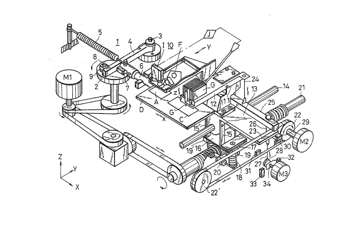
In Fig. 1, re~erence-letter D denotes a sliding table,
on which an original lmage A, such as a photograph of a
face, and a card C on which a ~ace photograph o~ the
original image A and other information (a picture image) are
&
engraved are fixedly mounted at a predetermined position,
which reciprocates in the direction of the X axis indicated
by the arrow in the ~igure. Reference numeral 1 denoted an
engraving table driving apparatus, connected to the sliding
table D, for making the sliding table D move from side ~o
side in the direction of thc X axis. The engra~ing table
driving apparatus ls connected via an motor M1, a belt, and
the like to the side o~ the sliding table D, in which
apparatus a prismatic ram 4, one end of which is pivotally
mounted on a supporting shaft 3 on the top surface of a
rotary disc 2 driven horizontally, is swingably mounted on
the right and left with the supporting sha~t 3 as the
center. As shown in Fig. 3, both sides of a square ram 4
are slidabl~ disposed in a state in which the ram 4 is
-fastened and pressed by a sliding operating piece 7 and a
sliding driving pie~e 9 by means of the energization force
of a tensile spring 5 because a rectangular or other
poly~onal sllding operating piece 7 rotatably mounted on the
~ront end of a driving shaft 6 energized by the tensile
spring 5 in an extension direction (to the left in Fig. 1)
by being extended from the sliding table D and a polygonal
sliding driving ptece 9 rotatably mounted by a pin 8 on a
predetermined rotational circumference on the top sur~ace o~
a rotary disc 2 are ~rought into surface contact with each
other on both sides of the ram ~. As a result, by making
.
2~7~
the rotary disc 2 rotate in the direction o-f the arrow in
the figure, the sliding driving piece 9 disposed on the
rotary di.sc 2 and the sliding operatin~ piece 7 mounted on
the Pront end of the driving shaft 6 are rotatably
dislocated with surface contact being main-tained in a state
in which the ram 4 is ~astened and pressed from both sides
thereo~ by the energization force o~ the tensile spring 5,
and they slide on the sides of the ram 4, causing the
sliding table D to reciprocate in the direction of the X
axis according to the rightward or leftward movement o~ the
ram 4.
Reference numeral 10 denotes a photoelectric scanning
mechanism disposed oppositely facing the original image A
above the slidlng table D, in which mechanism are integrally
housed a light source F. a photoreceptor I which condenses
light from this light source F and makes the llght strike
the original image A, and receives the reflected light to
detect the light and ~hade thereo-~, and a control circuit J.
Reference letter G denotes an ~engraving machine equipped
with a cutter head G' which moves vertîcally oppositely
facing the card C ln the direction of the Z axis above the
sliding table D. It is mounted on the front end of an arm
12 rotatably mou.nted in a vertical d~rection by means of a
pivoted pin 11 and dlsposed side by side integrally with the
photoelectric scanning mechanism 10 on a base 13 in such a
2~722~
manner as to be capable of operating in linkage with each
other. The photoelectric scanning mechanism 10 and the
engraving machine G are moved back and forth in the
direction of the Y axis on the sliding table D together with
the reciprocating movement o-f the base 13 in the direction
of the Y axis.
On the bottom surface o-f the base 13, on which the
photoelectric scanning mechanism 10 and the engraving
machine G are integrally disposed side b~ side, which moves
back and forth in the direction of the Y axis, a shaft 14
supported on a uniform bearing in such a manner as to be
capa~le of moving back and forth, is integrally fixed on the
bottom surface in the direction o~ the Y a~is; the lower
portion o-f two elastic swing plates 15 and 15', in which
elastic thin plates are formed in the form of the letter L
and are vertically disposed at a proper interval side by
side, are connected by an elastic connecting thin plate 16;
on the bottom sur~ace thereof are mounted gear wheels 19 and
19' pressed upward toward the connecting thin plate 16 by a
pressing spring 18 via a disc friction plate 17 and by a
spring 20 stretched mutually in the lower end thereof; a
gear wheel 21 to which is connected the motor M1 and driven
at a proper rotation speed by en~aging the shaft 14 in the
direction of the Y axis and placed side by side therewith
between the gear wheels 19 and 19'; the gear wheels 19 and
~7~2~
19' engaged with a worm gear 21 feed the base 13 in the
direction of the Y axis by the ro-tation of the worm gear 21
in a stationary state as i-f it is a nut without being
rotated by the f'riction plate 17; and the gear wheels 19 and
19' are rotated and moved in opposition to the ~rictional
resistance o-~ the friction plate 17 during the fast feed of
the base 13.
On the other hand. on the top surface of the base 131 a
belt 23 wound around a driving pulley 22 and a movement-
receiving pulley 22' of a motor M2 is movably disposed in
con-tact with the top sur~ace of the end section of the base
side in the direction of the Y a~is. A lever 25 connected
by a connecting material 24, such as wire, in such a manner
as to be capable of moving together in linkage with the arm
12, to the back end of the arm 12, one end of which is
rotatably in a vertical direction mounted on the base 13 and
ln the central section of which the engraving machine G is
mounted, above the belt 23. The opening/closing end of this
lever 25 is connected to an eccentric cam 28 of a motor M3
which moves ln one piece in the direction of the Y axis
below the base 13 by means of an operating member, such as
wlre, inserted into an insertlon hole 26 o~ the base 13. It
moves vertically by the rotation of the eccentric cam 28 to
fasten and press the belt 23 on the base 13 and causes the
engraving machine G to move vertically via the arm 12.
2~722~
Reference numeral 29 deno-tes an operating piece
integrally fixed to the ba~e 13; reference numerals 30 and
31 denote limit switches which operate by being br~ught into
contact with the operating piece 29, the limit switches 30
and 31 being disposed in accordance with moving distance of
the base 13 in the directlon of the Y axis; reference
numeral 30 denotes a stop-point limit switch; reference
numeral 31 denotes an engraving start-point limit switch;
reference numerals 32 and 33 denote switches which operate
via an operating piece 34 rotating integrally with the
eccentric cam 8 of the motor M3 to maintain the
opening/closing operation of the lever 25 disposed above the
base 13. As shown in Fig. 4, reference numeral 3~ denotes a
downward movement switch, and reference numeral 33 denotes
an upward movement switch. They are disposed in such a
manner as to oppositely face each other at a positional
difference of 180 across the operating piece 34 so as to
operate each time the eccentric cam 28 makes a half
rotation. When the limit switch 30 is operated by the
operating piece 29 provided on the base 13, the motor M3 is
rotated, causing. the lever 25 to move downward via the
eccentric cam 28. The operatlng piece 34 operates the
downward movement switch 32 so as to maintain the down~ard
movement state of the lever 25. The operation of the limit
switch 31 rotates the eccentric cam 28 to cause the lever
2~22~
25 to move upward. The operating piece 34 is disposed so
as to operate the upward movement switch 33 to maintain the
upward movement state of the lever 25, releasin~ the
connection with the belt 23.
Next, the operation of the apparatus will be explained.
In Fig. 1, the base 13 is moved backward along the Y axis.
The stop-point limit switch 3~ in contact with the operating
piece 29 is in an operating state. The operating piece 34
of' the motor M3 is brought into contact with the downward
movement switch 32, causing the lever 25 to move downward
via the eccentric cam 28. As a result, the belt 23 is
mounted on the base 13 in a fastened state and the engraving
machine G is lifted upward by the arm 12 connected to the
lever 25.
When the power-supply switch S shown in Fig. 6 is
turned on in this above state to close a starting switch
CS1, a contact point Acl is closed by a keep relay Ac, and
the motor M1 is actuated by a relay L1. The rotary disc 2
rotates in the direction of the arrow in Fig. 1. The
sliding driving piece 9 rotatably mounted on the rotary disc
2 and the sliding operating piece 7 pivotally mounted on the
front end of the driving shaft 6 pulled by the tensile
spring 5 slide on the side of the ram 4 in a state in which
the ram 4 is fastened from both sides while being dislocated
rotationally, causing the sliding table D to reciprocate
2137~2~
from side to side in the direction of the X axis via the
driving shaft 6. Although, at the same -time as the above
takes place, a worm gear 21 rotates, the base 13 is not
driven because the lever 25 which has moved downward fastens
the belt 23 on the base 13. At the same time, a contact
point Ac3 of the keep relay Ac is closed, and the operation
of the relay L2 causes the mo~or M3 to be started.
At this time, in the motor M2, the contact point la of
the relay L1 is closed. The base 13 is fed forward along
the Y axls via the belt 23 which has rotated forward and is
fastened by the lever 25, while the gear wheels 19 and 19'
engaged with the worm gear 21 are being rotated in
opposition to the resistance o~ the friction plate 17.
When the photoelectric scanning mechanism 10 reaches the
original ~mage A and the engraving machine G reaches an
engraving starting point on the card C, the operating piece
29 ~ixed to the base 13 actuates the engraving start-point
limit switch 31, thus releasing the energization of the
relay L2 to stop the motor M2 and energizing the relay L3 in
order to actuate the motor M3, thereby rotating the
eccentric cam 28. In response to this, the operating piece
34 is also rotated, causing the upward movement switch 33 to
be ac~uated. The motor M3 is stopped after it makes a half
rotation. Because the lower tensile force of the lever 25
is released by the eccentric cam 28, the engraving machine G
2~7~2~
falls on the cards C. The lever 25 moves upward and the
connection thereof with the belt 23 i5 released. The gear
wheels 19 and 19' become stationary due to the action of the
friction plate 17. In accordance with the rotation of the
worm gear 21, the photoelectric scanning mechanism 10 and
the engraving machine G are fed backward in a finely
adjusted manner along the Y axis v~a the base 13.
In this state. the original image A on the sliding
table D which moves from side to side in the X-axis
direction is photoelectrically scanned. The cutter head G'
of the engraving machine G is moved verticall~ in the Z-axis
direction by the electrical signals of the image. As shown
in Fig. 5, the sliding table D moves toward the right. The
cutter head G' is operated to perform an engraving only when
the sliding table D *ravels on an engraving line R. Control
is performed in such a way that no engravin~ is performed on
the return line S during the leftward movement of the
sliding table D. Thus, an image or the like is engraved on
the card C in accordance with the light and shade of the
original image A.
When the base 13 is fed backward and the operating
piece 29 is brou~ht into contact with the stop-point limit
switch 30, the energization of the keep relay Ac is released
via a reset coil Ar, a contact point Ac2 returns, and a
relay L3 is energized, thus causing the motor M3 to be
1~
2~7~2~
rotated. The lever 25 is moved downward by the eccentric
cam 28 rotating at the same time, causing the engraving
machine G to be separated from the card C. The operating
piece 34 contacts the downward movement switch 32, causing
the motor M3 to be stopped. The belt 23 is mounted in a
fastened manner by the operated lever 25. The motor M1 is
stopped by the contact point Acl and placed in the state
shown in Fig. 1. An engraving operation is performed on the
card C by repeating the same operation by operating a
starting switch CS1 again.
When the engraving machine G returns due to a delective
setting of the card C or the original image A, or the like,
if the reset switch CS2 is closed, the energiza$ion of the
keep relay Ac is released by the reset coil Ar. The contact
point Acl is opened, causing the motor Ml to be stopped.
And the contact point lb of the motor M2 ls closed, and the
motor M2 is connected reversely. The motor M3 causes the
eccentric cam 28 to rotate by the closure of the contact
point Ac2, making the lever 25 move downward. Hence, the
engraving machine G is lifted and the belt 23 is pressed in
a fastened state. At the same time, the downward movement
switch 32 is operated by the operating piece 34 and the
motor M3 stops. The motor M2 connected reversely is rotated
in reverse via the contact point lb as the result of the
closure of a contact point Ac4. While the gear wheels 19
,2Q~
and 19' engaged with the worm gear 21 are rotated in
opposition to the resistance o-f -the friction plate 17 by the
belt 23, mounted in a ~astened state by the lever 25,
traveling in a reverse direction, the base 13 is driven
forcibly fed rapidly bac~ward along the Y axis until the
operating piece 29 reaches the stop-point lirnit switch 30.
Thus, the state o~ Fi~. 1 is created in the same manner as
described above. An engraving operation is per-~ormed again
by the above-described operationO
Although, in this embodiment, a case in which the
original image A is photoelectrically scanned and engraved
was explained, a picture image from a TV or VTR lnstead of
the original image A is converted into electrical signals
and the image or the like can also be engraved by the
engraving machine G on the card C on the sliding table D.
As described above, according to the present invention,
the engraving table driving apparatus is designed to cause
the sliding table D to be reciprocated in the X-axis
directio~ by the ram 4 which swings from side to side with
the supporting sha~t 3 as the center via a sliding element,
such as the sliding driving piece 9 pivotally mounted on the
rotary disc 2. No special oil pressure generator is
requlred, unli~e a conventional apparatus which is driven by
a h~draulic cylinder. In addition, the apparatus does not
need to be enlarged without requiring a large rotational
- . .
:~ .
2~2~
radius as does an apparatus which is driven by an eccentric
cam. Thus, the apparatus can be produced small in si~e and
inexpensively.
Furthermore, the ram 4 is formed into a prismatic
shape. Sliding elements of the sliding driving piece 9, the
sliding operating piece 7, or the like, which slide on both
sides o~ the ram 4, are formed into a reetangular or other
polygonal shape and are brought into sur-~ace contact with
each other, serving as a sliding receiver. A smooth
operation is performed quietly without causing vibration.
Even i~ dust or dirt is stuck on the sliding surface of the
ram 4, it is removed by the above-mentioned polygonal
sliding elements which are in sur~ace eontact. Thus there
is no possibility that dust or dirt will collect on the
contact sur~ace. Such a case does not occur, unlike the
prior art, in which interference ~ringes occur in an image
due to the nonuniformity o~ the feed o-~ the sliding table D
caused by dust or dirt which enters on the contact surface,
thereby eausing defeets. As a eonsequence, images ean be
engraved elearly and accurately.
In the engraving table driving apparatus 1, a swinging
slider erank meehanism is used by means of which the sliding
table D is made to reeiprocate along the X axis by making
the ram 4 which rotates with the supporting sha-~t 3 as the
eenter move rrom side to side by means o~ the sliding
2~7~2Q~
driving piece 9 on the rotary disc 2. This mechanism is a
kind o~ fast-return mechanism in which the time of returning
a return line S is made earlier than the ~eed o~ the
engraving line R. The density o~ the engraving line R on
the card C is large, hence, the fidelity of the image is
considerably improved and a clear image can be engraved.
In a sliding element, one side o~ the polygonal is in
sur~face contact. When it is worn down, no replacement of
component members is necessary because the other sides
con~act and slide. There-fore, the apparatus can be used for
a long period of time. When it is desired to change the
ratio of time of the reciprocation o~ the sliding table D,
the ratio of time can be easily changed by changing the
distance from the cénter of the rotary disc 2 to the
supporting shaft 3 of the ram 4. As a result, an image
havlng the requlsite clearness can be easily engraved.
The feed of the engraving machine G along the Y a~is is
driven by causing a screw sha~t, such as the worm gear 21 or
the like, to be engaged with a supporting member ~ertically
pro~ided in such a manner as to be capable of being
dislocated by mutually connecting elastic swlng plates 15
and 15' on the bottom surface of the base 13, between the
gear wheels 19 and 19' which are stationary during normal
times and are made to rotate in opposition to the friction
plate 17 when an external ~orce is applied thereto. Even
18
2 ~
when a dislocation or the like due to a mounting error
occurs, to say nothing o-~ an eccentricity or bending o-f the
screw shaft, no machining with a high degree of accuracy,
centering, etc. needs to be performed. Unlike an apparatus
which is driven b~ screwing a screw sha~t to a conventional
nut, a condition of being inoperable to rotate or feed
nonuniformity due to changes in the frict~onal resis-tance of
the screw shaft does not occur. Not only can these errors
be satisfactorily absorbed, but the backlash of the screw
can also be absorbed because the gear wheels 19 and 19' are
engaged from both sides thereof by being fastened and
pressed. The apparatus can be produced at a low price.
Since a smooth feed operation can be performed, an image
having high fidelity can be engraved.
The belt 23 driven by the motor M2 is disposed on the
top sur~ace o~ the base 13 in parallel to the screw shaft
along the Y axis in such a manner as to be capable of
tra~elin~ in either a forward or reverse direction in
contact with the top ~urface of the end section of the base.
The lever 25 connected to the eccentric cam 28 is pivotally
mounted above this belt 23 in such a manner as to be capable
of vertically moving and capable o-f opening/closing and
mounting the belt 23 in a fastened state. Regarding the
feed of the engraving machine G to the engraving starting
point or a returning operation in the middle of the feed,
19
2~2~
the base 13 can be quickly fed along -the Y axis by making
the gear wheels 19 and 19' mounted on the base 13 rotate and
roll on the screw shaft in opposition to the friction plate
17 by making the lever 25 move downward so as to mount the
belt 23 in a f'astened state. The time required to process
the cards C is considerablY reduced, and a large amount of
cards can be engraved. Furthermore, the rapid feed
operation is performed by the clutch operation of the lever
25. Since the engraving machine G is lifted in linka~e with
the downward movement of the lever 25, no damage is caused
to the card C during the driving. The apparatus has many,
remarkable features, such as described above.
As has been explained above, according to the present
invention, the following advantages can be obtained.
Rapid feed can be used f`or the feed of the engraving
machine to the engraving starting point and a returning
operation therefor. Thus, time required to perform an
engraving onto a card can be shortened considerably.
~ ven when the eccentricity of a screw shaft, shaft
bending, dislocation due to mounting error or the like
occurs, unlike a conventional apparatus, no machining with a
high degree of accuracy, centering, etc. needs to be
performed. A condition of being inoperable to rotate or
feed nonuni~ormity due to changes in the frictional
resistance of the screw shaft also does not occur.
~0
, ~ ~
2 ~
Furthermore, the backlash o-f the screw can be absorbed. The
apparatus can be produced economically. Since a smooth feed
operation can be performed, an image ha~in~ hi~h fidelity
can be engraved.
~ nlike a conventional apparatus, no special oil
pressure generator is required and the apparatus does not
need to be enlarged and it can be produced at a low price.
A smooth operation is per-formed without causing
vibration. Even if dust or dirt is stuck on the sliding
sur-face of the ram, it is removed by polygonal sliding
elements which are in surface contact, thus there is no
possibility that dust or dirt will collect on the contact
surface. As a result, no defective image occurs.
Many different embodiments of the present invention may
be constructed without departing from the spirit and scope
of the present invention. It should be understood that the
present invention is not limited to the specific embodiment
described in this speeification, and is only limited in the
appended claims.