Note: Descriptions are shown in the official language in which they were submitted.
207233~
A METHOD OF FIXING A TAB AN
APPARATUS THEREFOR
This invention relates to methods of fixing a tab to a
fixing surface and/or apparatus therefor.
The present invention may be applied in areas where it
is necessary to fix a durable tab or label to products
that in the course of handling or use are exposed to
adverse conditions. The invention has also a broader
application by associating a reinforcing application tab
with a stapling fastening means and thereby can have
utilisation in fixing, for example, insulation or
building paper.
Accordingly, in one aspect the invention may broadly be
said to consist of apparatus comprising a housing,
impact means associated with said housing and operable
to deliver a penetrating fastening means into a surface,
feed means to feed a strip of material from which a tab
is to be cut, cutting means to separate the tab from the
strip, means to present the tab to a position where it
can be brought into contact with the surface and by
impact contact of a said penetrating fastening means by
said impact means fasten the tab to said surface, and
engagement means moved by and as a consequence of
movement of the impact means along a line of movement to
engage with and thereby cause said cutting means to
operate to separate the tab from the strip.
_ 3
2072334
In a further aspect the invention may broadly be said to
consist in stapling apparatus comprising a staple gun
having a primary pneumatic cylinder drivingly
cooperating with impact means, a housing incorporating
feed means for feeding a strip of material, cutting
means operable to cut a portion of material from said
strip to form a tab, and means to present said portion
of the strip to a position where it can be brought into
contact with a surface and fastened thereto by a staple
driven therethrough by said impact means, said feed
means including an auxiliar~ pneumatic cylinder coupled
direct to said primary pneumatic cylinder whereby
operation of said primary pneumatic cylinder causes
operation of said auxiliary cylinder to occur.
.. ~
,~,,
20~233~
One preferred form of the invention and modifications
thereof will now be described with reference to the
accompanying drawings in which:
Figure 1 is an end elevation of apparatus according
to the present invention,
Figure 2 is a side elevation of the apparatus
according to the present invention,
Figures 3 and 4 are end elevations of the apparatus
with the end cover plate removed and positioned to
one side to show the components used in the feed
and indexing mechanism of the apparatus,
Figure 5 is an exploded view of the components in
the cutting assembly of the apparatus, and
Figures 6 and 7 are schematic end elevations which
essentially correspond to the apparatus as shown in
Figures 3 and 4 respectively but show more
specifically the pneumatic circuitry.
The preferred embodiment of the invention has been
particularly designed to apply marking tabs or labels to
timber products such as logs or cut timber to associate
a tab or label with appropriate indicia thereon so that
the material can be identified, for example as having
, .
2072334
been satisfactorily treated through a preservation
system and of a standard suitable for use as building
material. This is one example only of a variety of uses
to which the invention can be applied. For example the
apparatus could be used to apply tags or labels to
wooden, cardboard or foamed or solid plastic
boxes/cartons to identify contents or product or
similar.
In this embodiment, a hand-held pneumatically operated
gun 1 is designed to feed staples from a magazine 2 to a
position to be driven by a driving head 3 into the
timber surface. The driving head 3 has associated
therewith an auxiliary driving head 4 which reciprocates
at the same time as the driving head 3 under the action
of the pneumatically operated gun 1.
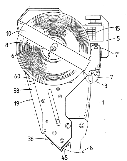
Associated with the gun 1 is a support plate 5 on which
is mounted a tape holding spool 6 on which is positioned
a reel of tape 8. The tape 8 is preferably of tough
durable material and preferably plastics. The tape 8 is
held in position by an arm 10 which has an offset
oversize opening 11 to allow the arm 10 to be moved
transversely and away from under head 9 of a the spool
pivot to allow a new reel of tape 8 to be loaded.
Any suitable holding means for a reel of tape could be
used in the present invention subject to the requirement
that the reel of tape can be readily loaded. The
6 2072334
mounting can include means for m;n;r;sing the likelihood
of overrun of the tape from the reel during use. Also a
housing can be employed so that the tape is protected
from jamming. A magazine holding the tape could also be
used to simplify replacement of the tape.
The tape 8 is fed from the reel around rollers 7 and 7'
mounted by cover plate 12 and support plate 5 to then
pass across a platen 13. This platen 13 is mounted by or
formed with a cam 57 pivotally mounted at 14. Thus
platen 13 can swing from a "disengaged" position (see
Figure 3) to an "engaged" position (see Figure 4). In
the latter position platen 13 moves into contact with
the printing indicia of a printing device 15. The
printing device 15 can be a standard printing device and
is permanently fixed on plate 5. This simplifies the
operation of the present assembly and allows sequenced
indicia to be printed onto tape 8 as the tape is moved
into association with the printing head using the action
of the platen 13 as will be described later.
The tape 8 continues about guide rollers 16 and 16'
designed to apply tension to the tape 8 but allow
relative movement so that movement of the platen 13 does
not cause any forces to be created which are likely to
pull upon the tape 8 thereby distorting or causing
smudging of the indicia printed by the printing head.
7 207233~
Printing device 15 includes an inking roller 17 which is
mounted so as to move from a rest position when the
platen 13 is against the printing head to the position
(shown in Figure 3) where the roller 17 moves over the
printing head to re-ink the head prior to each printing
sequence.
Tape 8 continues into a feed and indexing mechanism 19
and passes over a guide plate 20 formed with a mounting
plate 23 but located at right angles to the plane of
plate 23. Plates 20 and 23 are preferably formed
integrally with support plate 5.
The components in the feed and indexing means are best
seen in Figures 3 and 4. A double acting pneumatic
cylinder 22 is supported by mounting plate 23.
Pneumatic cylinder 22 is held in place by a mounting nut
25. The operating rod 26 of the cylinder 22 is
operatively associated with a feed head 27.
Pivotally associated with feed head 27 is an indexing
finger 32 operated against the biasing action of a
mounting pin 33 and a coil spring (not shown) so that
when feed head 27 is withdrawn finger 32 can pivot
forwardly to slide over tape 8 but when feed head 27 is
moved forwardly finger 32 will engage with tape 8 to
advance the tape 8. Finger 32 preferably incorporates a
protuberance 35 which engages within an aperture in tape
8, the aperture being located at indexed distances so
2072334
that when finger 32 engages in the aperture tape 8 will
be advanced a predetermined distance with slippage.
After leaving the feed and indexing mechanism 19 the
tape 8 is advanced through a cutting mechanism. The
cutting or guillotine assembly 36 is illustrated in an
exploded view in Figure 5. The guillotine assembly 36
has a tape support plate 37 which at its forward edge
provides the cutting edge 38. The tape support plate 37
has two side walls 39 and 40 preferably integrally
formed and formed from a suitable metal material. A
recess 41 is formed in plate 37 for tape 8 to pass. A
finger 42 formed as an extension of guide plate 20
locates between walls 39 and 40 and interacts with tape
8 to keep the tape in recess 41. This ensures tape 8 is
correctly located below cutting blade 45 prior to it
passing over the cutting edge 38. Cutting blade 45 is
pivotally mounted on support plate 37 with a pivot 46.
A biasing spring 47 mounted on a shaft 44 extending
between walls 39 and 40 has a first tail 48 which
engages in an aperture in blade 45 and is designed to
create a biasing movement holding the blade in the open
position. A second tail 48' engages with support plate
37.
The shape of the blade edge 49 relative to the cutting
edge 38 is such that as the blade pivots about pivot 46
the shearing action commences at a position remote from
207233~
pivot 46 and cuts with a shearing action toward the
pivot.
It is important to ensure that the cutting assembly can
cut tough plastics material at a high frequency
operation without fault and with clean cuts. The
operating sequence can be, for example up to 140
operations a minute and a malfunction of the cutting
means would be a major disadvantage. The cutting action
is created through an impact action with the movement of
auxiliary driving head 4 travelling the m~;mum distance
prior to cutting action taking place to allow for the
greatest possible time in the sequence to advance tape
8. Thus the cutting stroke takes place over a
comparatively small movement of the auxiliary driving
head 4.
A toggle 50 (see Figures 3 and 4) pivotally supported at
51 is impacted, in use, by the auxiliary driving head 4
to apply a pressure to the top 52 of cutting blade 45.
This impact action generates force which not only drives
cutting blade 45 to the cutting position but also forces
cutting blade 45 back against cutting face 38. Blade 45
is guided to its correct position through association
with the front faces of walls 39 and 40.
Figure 3 represents the apparatus in a "ready" position.
Upon actuation the apparatus moves to the configuration
as shown in Figure 4. As a consequence drive head 3
2072334
drives a staple S through the leading end of tape 8 and
as a result of the action of auxiliary driving head 4
cutter mechanism 36 cuts a tab T from tape 8.
Additionally feed head 27 is retracted by the action of
auxiliary pneumatic cylinder 22. This retraction of
feed head 27 results in a cam driver 53 sliding between
guides 54 on the inside of cover 12. A cam pin 55
engaged in slot 56 of cam 57 provides the driving force
which moves cam 57 about pivot 14 such that platen 13
moves to take up the position shown in Figure 4.
Drive head 3 may be profiled so that the corners are
relieved and the centre portion strikes the staple first
thereby creating a depression in the staple and thus
preventing it from driving right through the tab when in
contact with soft materials.
As the apparatus reverts from the position shown in
Figure 4 to that shown in Figure 3 protuberance 35 of
finger 32 applies a feeding force to tape 8 whereby the
leading end of tape 8 will become positioned for
application at the next operation of the device.
To maintain tape 8 on guide plate 20 a cover 58 is
provided. This cover 58 is hingedly coupled at one end
by hinge pin 59 and is releasably retained at its other
end by a latch 60 having spaced apart hooked portion 61
which engage in similarly spaced apart apertures 62 in
plate 20. Thus cover 58 can be pivoted away from plate
11 2072334
20 to enable tape 8 to be threaded through to the cutter
mechanism 36.
Mounted in a recess 63 in cover 58 is a tape stop 64
which is biassed by a spring 65. Thus as the feed head
27 moves from the position in Figure 3 to that of Figure
4 the tape stop 64 applies a pressure to tape 8 to
prevent it from retracting. However, as feed head 27
moves back to its Figure 3 position the tape stop 64
pivots (see Figure 3) to enable the tape 8 to advance
under the action of finger 32.
The sequence of events described above can be achieved
in a variety of different ways, however, the pneumatic
diagrams of Figures 6 and 7 disclose one means of
achieving the correct sequence.
In Figure 6 the apparatus is shown at rest. Air under
pressure from a pressurised air source (not shown) is
connected via line 66. This pressurises diaphragm
chamber 67 via line 68 and chamber 81 via line 70.
Line 71 pressurises auxiliary cylinder 22 so that the
piston 80 is held in the position shown in Figure 4.
Line 72 couples auxiliary cylinder 22 back to cylinder
chamber 69. Diaphragm 74 is coupled to a valve element
75 which is drawn off a seat such that the "top" end of
main cylinder 73 is vented to atmosphere via vent 76.
Piston 79 is thus held at the upper end of cylinder 73.
12 2072334
To actuate the gun trigger 77 is operated (see Figure 7)
which vents lines 68 and 71 to atmosphere via passage 78
of trigger 77. Thus a pressure differential is set up
which causes piston 79 to move to the "bottom" of
cylinder 73 and thereby drive a staple through a tape 8.
This also causes toggle 50 to actuate the cutting
mechanism to cut a tab T from tape 8. Simultaneously
piston 80 of auxiliary cylinder 22 is driven "upwardly"
to draw with it feed head 27.
Upon trigger 77 being released the positive pressure
applied via lines 71 and 72 causes pistons 79 and 80 to
reverse and this results in the equilibrium of Figure 4
to be reached and thereby complete the operating cycle.
The present preferred embodiment has been described in
association with a pneumatic staple gun. It will be
understood that the device could be adapted for
association with any suitable fastening means that can
operate at a fast sequence of operations. In the
present case an operator gripping the handle 83 can
activate the trigger 77 which commences the sequence of
operation. The operator would do this when the gun was
in contact with the material such as treated timber to
which a tab was to be applied and he would do the
application by a sweeping or wiping action so that the
stapling and cutting steps take place during such action
to thereby leave a single tab stapled to the timber.
The ùser with limited practice is able to develop an
13
207233~
aptitude to fix tabs using the present apparatus at a
very fast rate.
The present invention is also able to be adapted in a
number of different ways. For instance, the fastening
means may be provided not by metal staples but by a
plastic fastening which can be in the form of a staple
or in the form of a single spike passing through the
tab. It may also be adapted for automatic operator on a
processing line.
The device may also be modified so that the impact head
does not deliver a separate fastening means but the
fastening means is formed by deforming a section of the
tab so that it is embedded in the timber. With this
application suitable plastics material in the tab would
be utilized.
The preferred embodiment has been described with
particular reference to applying a tab to timber
products but the apparatus could also be used where it
was necessary to produce a reinforcing tab behind the
head of a staple that was, for example fixing insulating
material to a structural framework.
It should be appreciated that while the preferred
embodiment has been described with reference to a
pneumatic operation. The componentry that has been
illustrated in the drawings could have the same
14 2072334
operating sequence created using an electrically
operated gun or a hand powered stapler equipped with
suitable mechanics.