Note: Descriptions are shown in the official language in which they were submitted.
2a727~8
F I ELD OF THE I NVENT I ON
This invention relates to drawer mounting track
assemblies that downwardly tilt the drawer box as it is brought
from its horizontal retracted position to its fully extended
condition.
BACKGROUWD OF THE INVENTION
Drawers are usually movable about a generally horizontal,
plane from a retracted position, in which the drawer is generally
concealed within the chest of drawers, to an extended position,
projecting outwardly from the chest. Indeed, the drawers are
carried by lateral tracks which maintain the drawers within a
substantially horizontal plane, in their retracted as well as
extended conditions.
When these drawers are located at a relative high height,
visual inspection of the content of the drawer loading area, and
consequently manual access thereto, is difficult because the top
mouth of the extended, horizontal drawer is above the level of the
person's eyesight. This is of course undesirable, and inefficient.
United States patent No 2,839,349 issued in 1958 attempts
~20 to address the above-noted drawback. In this patent, means are
provided to downwardly forwardly tilt the drawer, as the drawer is
extended from its retracted horizontal condition, to enable easier
visual inspection of the drawer loading area. More particularly,
drawer B is carried by generally horizontal side tracks 8 depending
~rom a supporting frame A anchored to cupboard C, The bottom rear
ends of the lateral sides of the drawer box B include a downwardly
~72768
depending shoulder 17, and the front bottom ends of the lateral
side of the supporting frame A include stopper bolt S. As the
drawer is extended from its retracted condition, its extension
occurs mainly along a generally horizontal plane, for most of the
travel of the drawer, except for a short outwardmost travel
portion. During this short outwardmost travel portion of the
drawer, the shoulder 17 engages the stop S, thus biasing the drawe~
to tilt downwardly. This tilting motion therefore occurs only at
the~ very end of the drawer retraction travel displacement.
Such a late tilting of the extending drawer is
disadvantageous, because sudden pulling action on the retracted
drawer could jerk the drawer and generate possible accidental
release of the drawer content from the loading area to the ground.
OBJECTS OF THE INVENTION
The gist of the invention i5 therefore to improve upon
U.S. patent 2,839,349 by providing tilting means for drawer
extension, which will enable progressive, continuous downward tilt
of the drawer as the drawer is extended from its generally
horizontal, retracted position. .~-?
,20 An object of the invention is to provide such a tiltable
drawer assembly, where smoothness of extension or retraction motion
of the drawer is enhanced.
An object of the invention is to provide such a tiltable
drawer assembly, wherein the drawer can be stabilized in various,
partly extended tilted positions.
SUMMARY OF THE INVENTION
2072768
Accordingly with the objects of the invention, there is
disclosed a drawer, mounted under a cupboard by first tracks, and
rollingly movable along these tracks by fi~rst rollers depending
from the lateral sides of the drawer box. A pair of second,
downwardly-forwardly inclined tracks depend from the lateral sides
of the drawer box, and are rollingly engaged by second rollers
rotatably carried at the front end of the first tracks. As the
drawer is pulled out from its retracted horizontal position, it
progressively and continuously tilts downwardly to an extended,
downwardly- forwardly- inclined, limit position. The storage
drawer extended position facilitates visual inspection of the
loading area thereof, through its top mouth.
More specifically, the invention relates to a drawer
assembly destined to be secured to a generally horizontal, ground-
clearing panel and comprising: (a) first track means, destined tobe anchored to the underface of said panel; (b) a drawer box,
defining an inner loading area and a top mouth opening into said
loading area; (c) first roller means, rotatably carried by said
drawer box and rollingly engaging said first track means; (d)
second track means, anchored to said drawer box and extending in
a direction non parallel to said first track means; and (e) second
roller means, rotatably carried by said first track means and
rollingly engaging said second track means; wherein said drawer box
is movable along said first track means between a first, generally
horizontal, retracted position, located in generally vertically
underlying register with said first track means and with said
2072768
drawer top mouth being generally horizontal, and a second,
downwardly-outwardly tilted, extended, limit position, generally
clearing the area vertically underlying said first track means and
with said drawer top mouth being outwardly downwardly inclined; and
wherein during the displacement of said drawer box along said first
track means, said drawer box tilts in a progressive and continuous
fashion about the rotating axis of said first roller means.
BRIEF DESCRIPTION OF THE DRAWINGS
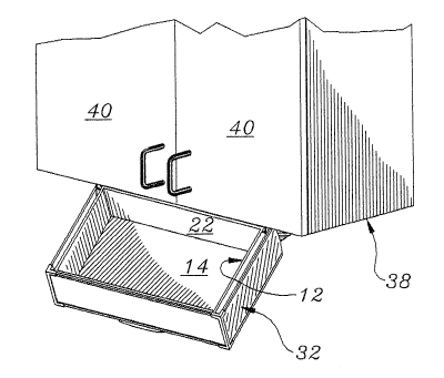
Figure 1 is a perspective view of the drawer assembly, shown
depending from a cupboard underface and in its extended, downwardly
tilted condition;
Figure 2 is an enlarged view of figure 1, but with the cupboard
being removed for clarity of the view;
Figure 3 is a partly exploded, perspective view of the two rail
brackets movably securing the drawer to the cupboard;
Figure 4 is a perspective view of the drawer, showing one of the
two inclined rails of the lateral sides thereof;
Figure 5 is a perspective view of the U-shape cover, for concealing
~ the front and lateral side walls of the drawer box;
., 20 figure 6 is a broken, front edge view of the drawer box and its
supporting rail brackets; and
figures 7-8 are lateral side views of the drawer box and associated
tracks, respectively in retracted and extended conditions of the
drawer, taken from perspective 7 of figure 6.
DETAILED DESCRIPTION OF THE INVENTION
Drawer 12, illustrated in figure 4, includes a
.
2072768
quadrangular flooring 14, four side walls 16, 18, 20 and 22, the
four side walls being generally orthogonal to flooring 14, and a
loading area 15 circumscribed by walls 16, 18, 20 and 22. Lateral
side walls 18, 20 each include on their external faces a cross-
sectionally U-shape rail 24 . Rails 24 are parallel to each other
and are forwardly downwardly inclined, preferably by an angle of
about 5' relative to the plane of flooring 14.
As clearly seen in figures 4 and 7, the rear ends 24e
(proximate rear wall 22) of rails 24 are farther away from the
plane of flooring 14, relative to the front ends 24d thereof, yet
rails 24 remain within the area located between the plane of
flooring 14 and the plane intersecting the drawer top mouth (i.e.,
the area circumscribed by the free edges 16a, 18a, 20a and 22a of
walls 16, 18, 20, 22). The web 24a of each U-shape track 24 is
applied and anchored flatly directly against the drawer side walls
18, 20 respectively, while their two top and bottom legs 24b, 24c
protrude away from these walls 18, 20 orthogonally thereto (i.e.
away from the drawer box 12). The front and rear ends 24d, 24e of
tracks 24 stop flush in register with front and rear walls 16, 22.
Each side wall 18, 20 includes an integral rear extension 18b, 20b,
extending beyond the plane of rear wall 22. Extensions 18b, 20b
are downwardly bevelled, each defining a larger top portion in
register with adjacent wall free edges 18a, 20a, 22a, this larger
top portion carrying an idle roller 28 rotatably journalled thereto
by axle 30.
As clearly seen in figure 7, each idle roller 28 is
2072768
located laterally outwardly of loading area 15, entirely beyond
the plane of rear wall 22 but short of the plane of free edges 16a,
18a, 20a, and 22a.
Preferably, for aesthetic reasons, a U-shape insert 32
(figure 5) is provided, being applied against the external faces
of side walls 18, 20 and of front wall 16, spacedly therefrom, to
conceal protruding tracks 24, 24. U-insert 32 includes a bottom
inturned lip 30a, for anchoring same to flooring 14 by screw means
(not shown), and a small handle 30b (figures 2 and 5), depending
from the central, bottom edge section of the front wall section of
U-insert 32, for facilitating handling of drawer 12.
A pair of rail brackets 34, 36 (figures 2-3) are
provided, to movably install drawer 12 beneath a cupboard 38
(figure 1), with drawer front wall 16 opening in underlying
vertical register with the access doors 40 of cupboard 38. Each
rail bracket 34, 36 forms an elongated, cross-sectionally U-shape
bar, defining a web 34a and 36a and two side legs 34b, 34c or 36b,
36c. Brackets 34, 36 are to be anchored to the bottom face o~ the
generally horizontal underface (not illustrated) of cupboard 38,
t 20 by screw members 42 engaging through bores 44 made in side legs
34b, 36b, so that channel members 34, 36 face one another, i.e.
with legs 34b, 34c directed toward legs 36b, 36c, while webs 34a,
36a extend generally vertically. Thus, the passageways of channel
members 34, 36 open toward one another.
The front portion of each bracket 34, 36 includes a
downwardly extending integral extension 34d, 36d of web 34a, 36a,
2~72768
on the side opposite anchor legs 34b, 36b respectively. Each
extension 34d, 36d is of increasing width, from a lengthwisely
intermediate section of bracket 34, 36 to the front end thereof.
The fore-located free end tip of each sector shape extension 34d,
36d carries an idle roller 46 journalled thereto on the side of
legs 34b-c, 36b-c by axle 48. As best seen in figures 8, most of
the peripheral surface of cylindrical roller 38 projects beyond
the free edges of the tip of extension 34d and 36d respectively,
so that the front and bottom rim portions of the roller clear the
bottom apex of extension 36d.
A stopper pin 50 (figures 3, 7) extends through a bore
52 made at the front end of each web 34a and 36a, opposite of
roller 38 but inwardly of anchor leg 34b, 36b. Stopper pin 50
protrudes through the inner channel of U-bar 34, 36, for a purpose
set forth hereinbelow.
As best seen in figures 7-8, each U-shape track 24 also
preferably includes, along its generally straight top leg 24b, a
short, small, downward boss 24f, spacedly proximate the front end
24d of track 24. Boss 24 reduces the width of track 24, about a
short length portion thereof, i.e. reduces the distance between
legs 24b and 24c. Boss 24b defines a smooth, convex, bottom
surface along which rollers 46 will rollingly engage, albeit with
some difficulty relative to the rest of the track length. The
purpose of boss 24f is to provide a rearward, yieldable seat for
roller 46, when drawer 12 is fully retracted, to prevent accidental
extension of the drawer (its opening) under its own weight below
2~72768
a given threshold biasing force level typical of manual pulling
force. This concern of accidental drawer extension will be
particularly acute when the drawer supports an important load of
tools.
Moreover, it would be advantageous to provide another
stopper 54 (figures 3 and 7) at the rear end of track 34 and 36,
for preventing rollers 28 from accidentally disengaging the aft end
of tracks 34, 36 upon drawer 12 being closed with great manual
pushing force. Stopper pins 54, as for stopper pins 50, would
preferably project from web 34a (or 36a).
Each roller 28 is diametrally smaller than the inner
width of cross-sectionally U-shape channel member 34, 36, for
rolling engagement therealong; and each roller 46 is diametrally
smaller than the inner width of cross-sectionally U-shape channel
member 24, for rolling engagement therealong.
In the assembled condition of drawer assembly 12 (figures
2, 7), the two rollers 28 rollingly engage into the U-channel of
inturned channel members 34, 36, while the two rollers 46 rollingly
engage outturned channel members 24, 24. It is understood that,
since externally located channel members 34, 36 are inturned (their
passageways open toward each other) while internally located
channel members 24 are outturned (their passageways open in
opposite directions), rollers 28 and 46 will be self-biased
rollingly into their channels 24 and 34, 36, against accidental
lateral egress therefrom. It is also understood that, since
rollers 46 are anchored to cupboard 38 via brackets 34, 36 ~1hile
2072768
rollers 28, 30 are anchored to drawer 12, rollers 46 are "fixed"
rollers whereas rollers 28, 30 are "movable" rollers.
In operation, with brackets 34, 36 anchored to the
underface of the bottom wall of cupboard 38, drawer 12 is rollingly
movable from a retracted horizontal position, shown in figure 7,
to an extended, downwardly-forwardly-inclined, limit position shown
in figures 1-2 and 8. Drawer 12 is smoothly movable between it~
retracted and extended positions (and vice-versa), due to the two
rollers 28, 28 rollingly engaging the lower runs 34c, 36c of
laterally spaced U-shape channel members 34, 36. Since tracks 34,
36 are preferably horizontal, the rolling displacement of movable
rollers 28 is also horizontal.
As rollers 28 move along tracks 34, 36, inclined rail 24
moves over rollers 46, thereby producing an apparent motion of
rollers 46 carried by the upper run 24b of inclined rail 24.
Because of the slope of tracks 24 relative to tracks 34, 36, and
also because rollers 46 move toward rollers 28 (during drawer
extension) or away from rollers 28 (during drawer retraction), as
the drawer is pulled out (extended) from under the cupboard 38,
, 20 under a horizontal biasing pull force, the drawer 12 will
progressively and continuously tilt downwardly and forwardly; while
as the drawer is pushed (retracted) from its fully extended,
downwardly tilted position, it will again tilt to regain its fully
retracted, generally horizontal po~ition parallel to the plane
intersecting topmost tracks 34, 36.
That is to say, it is by the combined action of the
2~72768
rolling displacement of rollers 28 inside hori~ontal U-tracks 34
and 36, together with the rolling displacement of the forwardly-
downwardly-inclined tracks 24 along support rollers 46, which will
enable tilt of the drawer during extension thereof.
It is understood that the specific angular value of the
forward, downward inclination of the inclined tracks 24, will
determine the final angular value of the fully extended drawer box
relative to the horizontal plane. Hence, the manufacturer will be
able to adapt the drawer assembly to specific needs by proposing
on the market a variety of drawers with tracks 24 of different
relative inclination, in view of a variety of use thereof: e.g.
taking in consideration the selected height of the supporting
tracks 34, 36, a greater inclination of inclined tracks 24 would
be selected if the supporting tracks 34, 36 are to be located in
situ at a relatively high height (for greater inclination of the
drawer to increase the ability of visual inspection of the drawer
loading area, from a constant view of sight standpoint).
The heart of the invention lies indeed in this
continuous, progressive tilt feature of the drawer unit, during
, 20 its retraction or extension. This continuous progressive tilt
feature is thus much different from known, prior art drawer units,
which provided sudden, stepwise drawer tilt only after drawer
extension travel had reached a given threshold level position. The
present drawer tilt feature therefore substantially reduces the
possibility of accidental release of material stored in the drawer
loading area 14, under conditions of abrupt force applied for
2~727~
drawer retraction.
It is understood that downward tilt of drawer 12 during
extension thereof from its stored (retracted) position, is
desirable, not only because of easier visual inspection capability
of the drawer loading area, but also because of easier manual
access thereto. Preferably, the ~ully extended drawer unit could
reach an angular value of downwardly tilted position making an
angle of up to about 45~, relative to the plane of tracks 34, 36,
for an inclination of about 5 of inclined track 24 relative to the
same horizontal plane of tracks 34, 36.
As suggested in figure 8, stopper pins 50, protruding
through the passageway of U-channel members 34, 36 at the front
ènds thereof, will prevent forward egress of rollers 28 from tracks
34, 36 and thus, will prevent further tilt of the drawer beyond its
fully extended, limit position, otherwise, one would undesirably
reach a vertical position where the material in the drawer loading
area 26 would escape therefrom to the ground.
Whenever there is made reference to the underface panel
of cupboard 38 being "generally horizontal", this is to be
understood as meaning that the ground-offset anchoring panel for
tracks 34, 36 could be slightly inclined relative to the horizontal
plane, for example by about 5-; in such a case, drawer tracks 24
would then become "horizontal" in the retracted position of the
drawer box.
Preferred materials and dimensions for the drawer
assembly are as follows:
2~727~8
- tracks 28 and 34-36: steel
- drawer box: molded plexiglass
- idle rollers 28, 46: nylon covered brass
- insert 32: polyvinyl chloride or wood, with a maximum thickness
S of about 1,6 millimeters.
It is understood that the loading area 15 of drawer box
12 is destined to receive a partitioning member (not illustrated)"
for subdividing loading area 15 into a plurality of compartments
for receiving inter alia: knives, utensils, spice bottles, recipe
booklets, and the like, in a kitchen; cosmetic products, combs and
brushes, in a bathroom; or audio and/or video cassettes, compact
discs and the like, in a playroom.
The ground clearance beneath drawer box 12 in its
retracted condition should of course be sufficient so that even in
the fully extended, downwardly tilted condition of the drawer box,
the latter will still clear the ground. For example, retracted
drawer box 12 will preferably be at a ground distance ranging from
four to five feet.
Preferably and as clearly illustrated in figure 6, at
least one top leg 24b of tracks 24 and at least one top leg 34b or
36b or tracks 34, 36 include a short, downturned lip on its inner
free edge. This latter lip is in closed proximity to rollers 28
or 46, parallel to their rolling plane, for substantially reducing
eventual accidental wobbling of the rollers 28 or 46 about their
rolling axles 30, 48 during high speed motion thereof along tracks
24 and 34, 36 (as when the drawer is opened or closed in a forceful
2~72768
f ashi on) .