Note: Descriptions are shown in the official language in which they were submitted.
20 72 771
-1-
The present invention concerns a screen
element, in particular for the
sorting/classification especially of fibre
suspensions, consisting of a plurality of parallel
5 bars, which are connected to one another by cross
bars and form a screen area and between which
slot-shaped screen openings are formed, which
essentially are at right angles to the main
direction of flow of the fibre suspension.
1o Furthermore, each bar is provided with plane,
parallel lateral faces which are at right angles to
the screen area and adjoin the end face of the bar
and which define the screen opening of two adjacent
bars.
15
With wear and tear, the abrasion of the
edges of the bars in the area of the screen opening
leads quickly to a greater slot width and
consequently to a deterioration of the quality of
2o the sorting. In order to reduce this, it has already
been suggested to limit the screen opening by
parallel side walls which run at right angles to the
screen area. By this means, the wear and tear could
be reduced and the life of the bars could clearly be
25 increased compared with bars with an approximately
triangular cross-section, the screen opening of
which is limited by diverging walls.
The object of the present invention is now
so to further reduce the wear and tear of the bars and
in this way to further increase the life of the
bars.
According to the present invention, the
35 above object is achieved by designing the parallel
side walls of the bars, which limit the screen
CA 02072771 2002-07-18
oPenin9. in such a way that - seen in the direction
of flow of the screen opening -- t:he downstream edge
of the side wall of the preceding bar is ahead of the
downstream edge of t:he side Wall of the subsequent
bar.
'the depth of the screen operxxng, which is
limited by the parallel side walls, or in other words
the overlapping of the parallel lateral faces of the
bars, which define the screen opening, is
approximately 0 , 2 to 0 . 8 mm, and in particular about
0.5 . The distance between the downstream edge of
the preceding bar and the downstream edge of the
subsequent bar, measured in the direction of flow of
the screen opening, is preferably about 1.0 to 2.0
times, and in particular about 1. 0 to :L . 5 times, the
parallel overlapping of the two bars. Suitably,
sloping lateral faces adjoin the parallel lateral
faces and form with respect to a normal of the Screen
area an acute angle of about ~.0 to 25°, iri which case
the angle of the sloping lateral face adjoining the
parallel lateral face of the subsernaent bar with
respect to a normal of the screen area is preferably
about 1~°, whereas the angle of the sloping lateral
face adjoining the lateral para:l.lel face of the
precedent bar with respect t4 a normal of the screen
axea x s px~e ~ exab~.y about ~ D ° .
The end face of each bar can be parallel to
the screen area, buy is preferably at an acute angle
to the screen area, which can range between about 10
to 30°, and in particular about 15°.
Therefore, in accordance with the present
invention, thex-e is provic7ed a screen element or a
screen basket, m partic:ul.ar for th2
sorting/classification particularly of fibre
suspensions, comprising a ~lura:lity~ of parallel bars
CA 02072771 2002-07-18
which ax-e connected to one another by cross bars and
form a screen area, and between which slot-shaped
scx-een openings are formed, which essentially are at
right angles to the main direction of flow of tha
fibre suspension, each parallel jar being provided
with plane, parallel lateral faces which extend at
right angles to Ghe screen area and which adjoin an
end face of said parallel bar, said parallel lateral
faces forming the screen opertir~g of two adj acent
parallel bars, the lateral faces of the bars, which
limit the screen opening, being designed in order
that, in the direction of flow 4hrough the screen
opening, at the screen opening, a trailing edge of
the lateral face of a preceding bar :is ah~aad of a
trailing edge of the lateral lace of a subsequent
bar' .
Also in accordance with the present
invention, there is provided ,a screening apparatus
for sorting and classifying a fluid flow; comprising
a PluxalztY of sc.r,-een e:leznen,ts mounted ozn cross bars
and defining a screen area, each of said screen
elements having a top surface, a first side face
including a plane wall section whi,ah extends from one
end of said top surface transversely to the screen
area, and a second side face including a plane wall
section which extends from the other end of said top
surface transversely to the screen area, wherein the
plane wall section of said first side face of on
screen element extends parallel to the plane wall
section of said second side faces of a successive
screen element tq define c~ ~cx'ee~n,~.ng slot
therebetween through which f~.uir:~ f:~ows, with each of
the plane wall sections of said first and second side
faces defining a downstream edgs~, with ~:iW down$tream
e~Ige of ttlE~ planE~ wall. section oz said i first side
CA 02072771 2002-07-18
-2b-
face of one screen element being provided in flow
direction of the fluid thraut~h S:3id :~creer~irlg slot
ahead of the dovmstream edge ~~f the nppasing plane
wall. section of said second side face of said
successive screen element.
An exemplified embodiment of the invention
is elucidated in the followir~g d~~sCriptaori with
zo~z7~1
- 3 -
reference to the sole figure of the drawing, which
shows in a schematical view in section two adjacent
bars of a screen element in accordance with the
present invention, between which a screen opening is
defined.
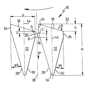
The figure shows two adjacent bars 12,
which form part of a screen element, e.g. of a
screen basket. The central axes 44 of the two bars
~0 12 run at an angle of 90° to the screen area 22 of
the otherwise not shown screen basket. The end faces
18 of the bars 12 can run parallel to the screen
area 22. However, in the illustrated embodiment, the
end faces 18 form with the screen area 22 an acute
~5 angle ,Q, which can be about 10 to 30°, and
preferably about 15°.
The two bars 12 are limited at both their
longitudinal sides by two plane lateral faces 24 and
zo 26, which originate at the ends of their respective
end faces 18 and extend in the direction of the
flow, which is indicated by the arrow P, in the
screen opening 16. The two lateral faces 24 and 26
extend at right angles to the screen area 22 and
zs thus parallel to the median plane 44 of the bars 12
and parallel to the median plane 38 of the screen
opening 16, which is formed between the two adjacent
bars 12. Moreover, the bars 12 are each limited by
two lateral faces 28 and 30, which form with a
3o normal on the screen area 22 and thus also with the
median plane 44 and the median plane 38 the angles ~pz
and ~~, respectively. The screen opening 16 is
limited by the lateral face 26 of the left bar 12,
the lateral face 24 of the right bar 12, which run
35 parallel to one another, as well as by the lateral
f ace 3 0 of the lef t bar 12 and by the lateral f ace
20 7277 1
-4-
28 of the right. bar 12, which form the aforesaid
angles ~p~ and ~p2 with the median plane 38 of the
screen opening 16.
s In the embodiment of the present invention
represented in the drawing, the parallel faces 24
and 26, which limit the screen opening 16, are
staggered one with respect to the other in the
direction of the flow P, in which case the lateral
~o face 26, in the direction of flow P, is offset
against the lateral face 24. However, the two
lateral faces 24 and 26, which form and limit the
screen opening 16, overlap by the measurement U, in
which case, as the figure shows, the edge A of the
15 left bar~l2 (formed by the intersection of the faces
26 and 18) is ahead of the edge C (formed by the
intersection of the faces 28 and 24) of the right
bar 12. The parallel screen opening 16 thus extends
in the direction of flow P, seen from the edge A of
2o the left bar 12, to the edge C of the right bar 12.
The overlapping U can be a few tenths of a
millimeter up to about 1 millimeter, preferably
about 0.2 to 0.8 mm, and particularly preferred
about 0.5 mm, seen in the direction of flow P.
As the figure shows, the lateral face 26
of the left bar 12 (which relative to the direction
of rotation of the rotor, indicated by the arrow,
corresponds to the subsequent bar) now extends
3o further in the direction of the arrow P than the
lateral f ace 24 of the right bar 12 ( which relative
to the direction of operation of the rotor,
indicated by the arrow, corresponds to the preceding
bar). In other words, the downstream edge B of the
left bar 12 (formed by the intersection of the faces
26 and 30) extends further by the measurement T
-5-
towards the direction of flow of the screen opening
16, indicated by the arrow P, than the downstream
edge C of the right bar 12, which is formed by the
intersection of the lateral faces 24 and 28 of the
s right bar 12. The measurement T can hereby be about
1.0 to 2.0 times, and in particular about 1.0 to 1.5
times, the overlapping U of the two parallel lateral
faces 24 and 26. (If the end faces 18 of the bars 12
run parallel to the screen area 22, which is not
~o represented here, the lateral face 26 of the left
bar 12, seen in the direction of flow P, is longer
by the measurement T than the lateral face 24 of the
right bar 12).
15 It has been observed that the wear
behaviour of the bars 12 in the area of the screen
opening 16 can be improved by the asymmetric design
of the lateral faces 24 and 26, which define the
screen opening, and the life of the bars (i.e. their
zo period of use) is increased by ca. 15$ to 20$
compared with such bars which limit the screen
opening with two parallel, equally long and not
staggered side walls.
2s With the wear and tear of the edge A, the
slot width of the screen opening 16 remains constant
until the edge A, i.e. the intersection between the
faces 18 and 26, becomes lower than the edge C.
However, with further wear and tear, the slot width
3o also increases slowly since also the parallel face
26 of the left bar 12, which furthermore is parallel
to the median plane, is present and extends to the
downstream edge B. With further wear and tear, the
result is therefore only an enlargement of the
35 screen opening due to the slope of the face 28 of
the right bar 12. Due to the lateral face 26, which
20~2~'~1
- 6 -
forms a wear face and runs parallel to the direction
of flow P, the enlargement of the screen opening 16
is thus reduced. The angles ~~ and ~2 are preferably
about 15$. An increase of the angle ~2 to about 20~
s leads admittedly to a somewhat quicker enlargement
of the screen opening 16, but it has turned out that
the resistance to flow could hereby be reduced.
In the shown embodiment, the width b of
~o the bar can be about 1.5 to 4 mm and the height H of
the bar 2.5 to 7 mm. The height h is the result of
the width b of the bar and of the angle (3.
The slot width of the screen opening 16 is
~s approximately in the range of 0.05 to about 1 mm.