Note: Descriptions are shown in the official language in which they were submitted.
Wal91/0~15 ~-: ~ PCT/US90/06238
2~0 7 2r9 7 6
MOLD CLAMPING SYSTEM
TECHNICAL FIELD
The present invention relates to a mold clamping
system, for example for a plastics injection molding
machine, in which the clamping system operates to move a
movable mold section toward and away from a stationary mold
section to define a closed mold cavity to permit high
pressure injection molding of a part made from pIastics
material. More particularly, the present invention relates
to a mold clamping system in which the relative movement
between the mold sections is performed by a pair of
electric motors, each of which drives a respective ball nut
to advance a single, non-rotatable screw that is attached
to a movable platen that, in turn, carries a movable mold
section. The motors selectively move the movable mold
section into and out of contact with a stationary mold
section mounted on a fixed platen.
BACKGROUND ART
Until relatively recently, in commercial practice the
mold closing and clamping systems in machines such as die
casting or injection molding machines were traditionally
hydraulically driven, the hydraulic devices including one
or more actuators of the piston-cylinder type for rapid
traverse of the movable mold section as well as for
applying clamping forces to maintain the mold sections in
contact during injection of the material into the mold
cavity under high pressure. Further, the use of hydraulic
drives extended both to hydraulic-cylinder-operated
machines, in which a large diameter movable ram is carried
within a large diameter hydraulic cylinder to provide the
required high clamping forces to maintain mold sections in
closed condition during an injection operation, as well as
to toggle-type machines utilizing a series of
~,
WO91/0~15 2 0 7 2 9 7 6 PCT/US90/06238
interconnected links or levers to actuate and control the
movement of the movable mold section.
However, with the advent of more sophisticated
electrical control systems for monitoring and controlling
the various structural elements of molding machines during
the various steps involved in a molding cycle, it was found
that the use of hydraulic motors and hydraulic actuators
resulted in a limitation on the degree of control that
could be obtained by such sophisticated electrical control
systems. For example, hydraulic-fluid-operated mold
clamping systems are not capable of the precision
corresponding with the precision attainable with electrical
control systems, principally because of the small, yet
me~ningful, compressibility effects of the hydraulic fluid,
as well as the heating and consequent expansion that the
hydraulic fluid undergoes during the course of a number of
molding cycles.
Although reasonably good control has been achieved in
hydraulically-operated clamp systems, a different drive
arrangement must be used if it is desired to attempt to
reduce further the overall molding cycle time, which
directly influences the cost of the molded parts. Although
electric motor drives for mold clamping systems have been
suggested in the past, see, for example, U.S. Patent
2,484,712, which issued October 11, 1949 to Jobst, and
United Kingdom Patent 1,136,573, which was published on
December 11, 1968, there has not been widespread use of
electric motor drives. Moreover, each of those patents
discloses an electrical drive system in which an electric
motor drives a mold closing and clamping system through a
gear transmission which, because of the accumulation of
mechAn;cal tolerances in the several interconnected parts,
is incapable of sufficiently precise control of a movable
platen position. Furthermore, the above-identified United
Kingdom Patent discloses a system utilizing a mechanical
flywheel, which results in a system having a great deal of
wa, 91/0~15 = --- PCT/US90/06238
--, r~
3 2072976
inertia, thereby further rendering difficult the precise
and rapid control of the mold closing and clamping system.
Accordingly, it is an object of the present invention
to provide an electric-motor-type drive arrangement for the
clamping system of a molding machine.
It is another object of the present invention to
provide an electrically-driven mold clamping system in
which a pair of motors are provided, one of the motors
being operable to effect rapid traverse of a screw
0 connected with a movable platen, while the other motor is
operable when the movable platen has reached the limit of
its path of travel, in order to provide a high clamping
force in order to tightly clamp the movable mold portion
against the stationary mold portion.
~L5 It is a further object of the present invention to
provide an electrically-operated mold clamping system that
is capable of precise control to minimize dead time during
a molding cycle, and to thereby reduce the overall time for
a single operating cycle.
ZO
DISCLOSURE OF lNv~llON
Briefly stated, in accordance with one aspect of the
present invention, a molding machine is provided for
molding materials that are injected into a mold cavity
2 5 defined by a pair of cooperating mold portions. The
machine includes a mold clamping system for opening and
closing a pair of cooperating mold portions, the clamping
system including at least one movable platen that carries
a mold portion toward and away from an opposed mold
~0 portion. A platen drive arrangement is connected with the
movable platen for moving the movable platen toward and
away from a second, stationary platen. The platen moving
arrangement includes a screw that is secured to the movable
platen in non-rotational relationship therewith, and a
'~ 5 first drive operatively connected with the screw for
rotational engagement therewith for axially moving the
screw at a first linear speed. A second drive arrangement
WO91/06415 2 0 7 2 9 7 6 PCT/US90/06238
=. 4
operatively connected with the screw is provided for rota-
tional engagement therewith for axially moving the screw at
a second linear speed, wherein the second drive arrangement
is adapted to provide a larger output torque than is the
first drive arrangement. The first drive arrangement is
activated to cause rapid traverse of the movable platen
toward and away from the stationary platen, and the second
drive arrangement is activated to cause slow traverse of
the movable platen toward the stationary platen to bring
0 the platens into contacting relationship and to hold the
platens together tightly with a contact force that is
sufficient to offset an Qppositely directed force resulting
from the injection into the mold cavity of pressurized
plastic material~
BRIEF DESCRIPTION OF DRAWINGS
Figure l is a top view of an injection molding machine
having a mold traversing and clamping arrangement in
accordance with the present invention.
Figure 2 is a side elevational view, partially in
section, of the injection molding machine shown in Figure
l, in which the upper half of the figure shows the parts of
the mold clamping system in their relative positions when
the movable platen is in its right-most position with the
mold sections engaged, and in which the lower half of the
figure shows the respective parts in their relative
positions when the movable platen has been withdrawn from
and is fully retracted away from the stationary platen.
Figure 3 is an elevational view taken along the line
3-3 of Figure 2.
Figure 4 is an elevational view taken along the line
4-4 of Figure 2.
Figure 5 is an elevational view taken along the line
5-5 of Figure 2.
Figure 6 is a block diagram showing a control
arrangement for the injection molding machine shown in
Figures l and 2.
WO91/0~15 2 0 7 2 9 7 6 PCT/US90/06238
.
Figure 7 is a sequence diagram for the injection
molding machine shown in Figures 1 and 2, identifying the
several portions of a single operating cycle of the
machine.
BEST MODE FOR CARRYING OUT THE lN V~N'l'lON
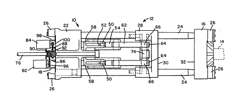
Referring now to the drawings, and particularly to
Figures 1 and 2 thereof, there is shown a mold clamping
system 10 of an injection molding machine 12. Although an
injection molding machine includes a mold clamping system
10 as well as a plastication and injection system 14, only
the mold clamping system has been shown in detail because
those skilled the art are familiar with the possible forms
of plastication and injection systems that can be employed.
Each of the mold clamping system 10 and plastication and
injection system 14 is mounted on a base (not shown). For
illustrative purposes, plastication and injection system 14
can be a typical reciprocating screw injection unit of a
type that is well known to those skilled in the art.
It should be noted at the outset that although
described herein in the context of a plastics injection
molding machine, the present invention is also applicable
to metal die casting machines, rubber molding machines, as
well as to other machines wherein rapid movement of one
part relative to another part is desired, along with a high
force to hold the two parts in predetermined positions.
Clamping system 10 includes a stationary platen 16 to
which is secured one mold section 18 that includes a
portion of a mold cavity 20 that defines the outer surface
of a desired part to be molded. Spaced from stationary
platen 16 along a longitll~;nAl axis is a die height platen
22 which, like stationary platen 16, is secured to the
machine base (not shown). Exten~;ng between stationary
platen 16 and die height platen 22 are four cylindrical tie
rods 24, which are preferably disposed in a square or a
rectangular array with their axes parallel with each other.
Stationary platen 16 and die height platen 22 are secured
WO 91/06415 2 0 7 2 9 7 6 PCT/US90/06238
.
to the tie rods by means of respective nuts 26 that are
threadedly engaged with an external thread (not shown) that
is formed at the respective longitll~i n~ 1 ends of each of
tie rods 24.
Slidably carried on tie rods 24 is a movable platen
28, which is of generally rectangular configuration and
which includes a face 30 that is opposite to and in facing
relationship with a corresponding fixed face 32 on station-
ary platen 16. Face 30 of movable platen 28 carries mold
section 34 that includes another portion of mold cavity 20.
Mold section 34 is adapted to be cooperatively engaged with
mold section 18 to define therebetween a closed mold cavity
20 of a particular shape to provide molded parts having the
desired outer configuration.
As best seen in Figure 2, die height platen 22
includes a recess 36 that faces movable platen 28 and is
adapted to receive a movable crosshead 38 that is slidably
carried on a pair of vertically spaced, parallel crosshead
guide rods 40 (see Figure 3), each of which has its
respective longitudinal axis positioned within the
rectangular cross section defined by tie rods 24, and
disposed in parallel with the longitll~in~l axes of tie rods
24.
Movable crosshead 38 includes a vertically-extending
center member 42 that carries a pair of spaced, parallel
sleeves 44 through which respective crosshead guide rods 40
pass. Movable crosshead 38 also includes two pairs of
laterally spaced upper link supports 46 and two
correspondingly arranged pairs of lower link supports 48
that extend from movable crosshead 38 in a direction toward
movable platen 28. Each of upper and lower link supports
46, 48 includes a respective pivot 50, to which one end of
a respective idler link 52 is pivotally connected. Thus,
movable crosshead 38 carries four such idler links 52. The
opposite ends of each of idler links 52 are connected with
respective first links 54 at an intermediate position
between the spaced ends of each of first links 54. One end
W~l9l/0~l5 . 2 0 7 2 9 7 6 PCT/US90/D6~3~
56 of each of first links 54 is pivotally carried in a yoke
58 that extends outwardly from die height platen 22 toward
movable platen 28. The other, opposite ends 60 of each of
first links 54 are pivotally connected with one end of
respective second links 62, the opposite ends 64 of which
second links 62 are each pivotally connected with movable
platen 28 through respective pivots 66.
As best seen in Figure 2, the initial positions of the
respective movable parts of clamp system 10 are shown in
.io the lower portion of the figure, wherein movable crosshead
38 is received within recess 36 of die height platen 22,
with respective first and second links 54 and 62 defining
a V. As movable crosshead 38 is shifted toward the right,
as viewed in Figure 2, upper and lower link supports 46, 48
.15 carry idler links 52 to the right, thereby pivoting the
lowermost first links 54 in a counterclockwise direction
about respective pivots 57, and the uppermost first links
54 in a clockwise direction about their respective pivots
57. The pivotal movements of first links 54 move second
:20 links 62 in a direction toward stationary platen 16, as a
result of which movable platen 28 is shifted along tie rods
24 from left to right, as viewed in Figure 2.
When movable crosshead 28 has moved from left to right
the maximum distance, the positions of the respective parts
:25 are as shown in the upper half of Figure 2, in which the
respective longitll~inAl axes of connected ones of first and
second links 54, 62 are aligned, with the result that
movable platen 28 is moved to its right-most position
relative to die height platen 22. As a consequence, mold
.30 sections 18 and 34 are brought into cooperative
relationship and define therebetween closed mold cavity 20
that is adapted to receive molten plastic material from
injection unit 14, which injects softened and flowable
plastic material through a sprue (not shown) that extends
.35 from mold cavity 20 through the rightmost wall of
stationary mold section 18, and communicates with
WO 91/06415 ~ ` 2 0 7 2 9 7 6 PCT/US90/06238
. e ~ - F
passageway 70 (see Figure 5) in stationary platen 16, with
which passageway injection unit 14 communicates.
After the nece~CAry quantity of molten plastic r
material is injected into closed mold cavity 20, and after
a sufficient cooling period has elapsed, movable crosshead
28 is retracted by moving it from right to left, as viewed
in Figure 2, to separate mold sections 18 and 34 a
sufficient distance to permit removal of the resulting
molded part. In that connection, an ejector cylinder 72
0 can be provided on movable platen 28 to shift an e~ector
plate 74 that carries one or more ejector rods (not shown)
to eject the molded part from movable mold section 34,
whereupon movable crosshead 28 can again be moved toward
the right, as viewed in Figure 2, to position the mold
sections for receiving a second shot of molten plastic
material to form a second part.
Referring once again to Figure 2, and particularly to
the lower half thereof, movable crosshead 28 includes a
ball screw 76, that is non-rotatably secured thereto by
means of a nut 78. Ball screw 76 is positioned to extend
from movable crosshead 38 in an opposite direction from
movable platen 28 and through the transversely extending
end wall 80 of die height platen 22.
As best seen in Figure 1, ball screw 76 is driven by
a pair of electric motors 82, 84 through respective toothed
belts 86, 88 that are adapted to drive respective ball nuts
90, 92, each of which is rotatably carried on ball screw 76
and is adapted to be rotatably engaged therewith. Among
the types of motors that can be used are servomotors,
induction motors, DC brushless motors, and the like.
As best seen in Figure 1, motor 82 is supported from
a housing 94 that houses drive sprocket 96, and is secured
to rear wall 80 of die height platen 22. Similarly, motor
84 is supported from a housing 98 that houses drive
sprocket 100 and is also secured to rear wall 80 of die
height platen 22, on the laterally opposite side of a
vertical centerline passing through ball screw 76. As is
wa~ 9l/06415 ~ ;~ 2 0 7 2 9 7 6 PCT/US90/~6238
apparent from Figure 1, drive sprocket 96 has a larger
diameter than drive sprocket 100 and, consequently, the
former causes more rapid rotation of its associated ball
nut 90 than does drive sprocket 100 to, in turn, cause more
rapid linear movement of ball screw 76 in a direction based
upon the direction of rotation of the ball nut. Thus
associated motor 82 is adapted to provide rapid traverse of
movable crosshead 38.
On the other hand, motor 84, which carries smaller
L0 diameter drive sprocket 100, is adapted to rotate its
corresponding ball nut 92 at a slower rotational speed, to
thereby impart greater torque to ball screw 76.
The respective ball nuts 90, 92 are spaced from each
other along the axis of ball screw 76 and are also spaced
:L5 from rear wall 80 of die height platen 22 and the inner
wall of the housing by means of thrust bearings 102, which
can be of any convenient type, as will be appreciated by
those skilled in the art. The positions of the respective
motors 82, 84 and the differences in sizes of the respec-
tive drive sprockets 96, 100 are also apparent in Figure 4of the drawings.
The operation of the respective motors 82, 84 is
controlled by a control system that is schematically
illustrated in Figure 6. As there shown, each of motors
;'5 82, 84 is connected to a motor control unit 104 that is
adapted to operate the respective motors during
predetermined portions of a molding machine operating
cycle.
Because the present invention contemplates very
:30 accurate control of the longitll~in~l position of the ball
screw, an external, linear position transducer 106 is
provided for determining the position of ball screw 76
relative to die height platen 22. Another possible form of
ball screw position sensor can be, for example, an internal
:35 angular position encoder (not shown), and it is possible to
provide that encoder in either motor because each of motors
82, 84 is normally continuously connected with ball screw
WO 91/06415 2 Q 7 2 9 7 6 PCT/US90/06238
76, and therefore either motor can provide the sensing
point for a suitable output signal representative of the
longitll~;n~l position of the ball screw.
An operating cycle for an injection molding machine
incorporating the mold clamping system in accordance with
the present invention is shown in Figure 7, which shows an
operating cycle that begins when the mold halves are
separated from each other by a predetermined distance that
is sufficient to permit a molded part to fall from the mold
cavity to a suitable part collector positioned below the
mold portions. Initial movement of movable platen 28 and
movable mold section 34 toward stationary platen 16 and
stationary mold portion 18 is accomplished through the
operation of rapid traverse motor 82, referred to in Figure
7 as "servomotor #l," although as earlier noted other types
of motors can also be employed. Rapid traverse motor 82
is energized until a position has been reached at which
first and second links 54 and 62 are each in their extended
position, as illustrated in the upper half of Figure 2, and
movable platen 28 is so positioned that movable mold
section 34 is either very close to or in very light initial
contact with stationary mold section 18. At that point
motor 84, the high torque clamping motor, referred to in
Figure 7 as "servomotor #2," which also can be another type
of motor, is energized to provide a high torque input to
the ball screw. Simultaneously with the startup of high
torque clamping motor 84 rapid traverse motor 82 is dropped
off-line and remains connected with ball screw 76 to free-
wheel during the time high torque motor 84 is in operation.
The latter then supplies the required torque to ball screw
76 to move movable mold section 34 any r~ining distance
toward fixed mold section 18 to cause the two mold sections
18, 34 to tightly engage and define closed mold cavity 20.
When molten plastic material is injected from injection
unit 14 into mold cavity 20 at high pressure, the resulting
force of the high pressure material acting on the projected
area of mold cavity 20 of movable mold section 34, which
O91/06415 = ~ ~ 2 0 7 2 9 7~ PCT/US90/0623X
n ~
11 _
force acts in the direction of die height platen 22 and
tends to move mold section 34 in a direction away from
stationary mold section 18, is counterbalanced by the
opposite force resulting from the torque provided to ball
screw 76 by high torque motor 84.
After mold cavity 20 has been filled with the molten
material, and after a sufficient time period has elapsed
within which the material inside the mold has cooled to a
sufficient extent that the resulting molded part will
:Lo maintain its shape, clamping lO unit is opened by initially
operating high torque motor 84 in a reverse direction, as
compared with the direction of rotation to move the mold
sections together, and upon initial separation of the mold
sections high torque motor 84 is dropped off-line, but
I5 remains connected to ball screw 76, and rapid traverse
motor 82 is brought on line to rapidly retract movable
platen 28 and movable mold section 34 away from stationary
mold section 18 until a predetermined distance has been
reached, at which point ejector plate 74 is actuated by
,'0 ejector cylinder 72 to eject the molded part from the mold,
and thereby permit the mold sections to be brought together
once again for molding another part during the next molding
cycle.
INDUSTRIAL APP~ICABILITY
The disclosed clamp drive system permits very accurate
control over the position and operation of the movable
platen of a molding machine, thereby allowing the machine
to be operated so that there is a minimum overall cycle
~0 time, resulting in economically produced parts.
In addition to the applicability of the present
invention to a mold clamping system for an injection
molding machine, the present invention can also be used in
other machines in which molds are used to define molded
articles made from other materials, such as die casting
machines for forming metallic articles, and rubber molding
machines for molding rubber articles. Additionally, the
WO91/06415 ~ 2 0 7 2 9 7 6 PCT/US90/06238
~ = ~
. 12 .
invention can also be used in other applications where a
low torque is required for a rapid traverse operation and
a high torque is required for a subsequent operation, such
as in a machine tool in which rapid traverse is desired for
moving a workpiece by means of a screw-operated conveying
and feeding system to carry a work holder from a loading
station to a cutting or forming station, and then providing
a high feed force to feed the workpiece against a fixed
cutting or forming tool.
Although particular embodiments of the present
invention have been illustrated and described, it will be
apparent to those skilled in the art that various changes
and modification can be made with out departing from the
spirit of the present invention. Accordingly, it is
intended to encompass within the appended claims all such
changes and modifications that fall within the scope of the
present invention.