Note: Descriptions are shown in the official language in which they were submitted.
207~
nl4150-0~ 2 ~
Proce~s for the rotary truing of planks and the like
The invention concerns a process for the rotary truing of planks and the
like around their longitudinal a~es by means of a plank guide channel through
which the planks pass in the longitudinal direction, said channel hsving a twist
around the longitudinal a~is which is varisble by adju6ting the parts forming the
plan~ guide channel.
In the case of a known straightenin8 apparatus (D~-B-32 07 548), planks and
in particular planks cut from the sides of a flattened tree trunk by a chipless
cutting methot are 6traightened, together with similar flat wood products such
as plates with A curvature around a transverse axis, between rolls.
Howuver, primarily the bo4rds or the like (al~o dusignutud plate~) produced
by the chiples0 method describud frequently exhibit in addition to the
abovementioned curvature a twist, i.e. they are twisted or turned around their
longitudinal axis. This teformation in numerous applications prevents any
automatic further processing of the boards. The twist increases with the angle
of inclination of the blades cutting the board against the longitudinal direction
of the trunk.
A known process of the abovementioned generic type (D~-A-37 01 127) is used
to straighten the boards produced. ~or the purpose, the boards pass through a
board guide chanDel with a spiral distortion, i.e. a twist around its longitudi-
nal a~is. In this manner, the boards are given a continuous twist in the course
of their passage in a direction opposite to their original twist. In the
process, the boards are straightened so that they then have a permsnent strai8ht
shape.
The intividual parts forming the board guide channel, for example pairs of
rolls, may be pivoted, 80 that a more or less inten~ive twi~t of the board guide
2~ $
014150~D71 _ 3 _
chunnel may be aet as u function of the straightening effect required. It is
pou~ible in this fa~hion to adapt the known process aa needed. The adjustment
of the board guide channel is carried out in sccordance with empirical values
primarily ~n a function of the twist present in the untreated bosrds. If the
boarda still have twists after passing through the board guide channel, the
setting of the board guide channel i5 altered until a satisfactory result is
obtained. The6e adjustment actiYitieS are very e~pensive, mainly because the
initial state of the boards varies frequently and because the physical and
chemical propereies of the wood also have a significant effect.
It is further known (D~-A-36 23 235), to utilize the humidity of the wood
to regulate a proces~ing parameter in the chipless cutting of boards from a tree
trunk. In this process the measured value of the humidity of thc wood is used
~o v~ry the contact pras~ure of a pressure beam which applies pressure to the
point st which the bosrds are cut. No straightening process is provided.
It is therefore the object of the present invention to develop a process
of the aforementioned generic type 50 that -- beginnin8 with an initial setting -
- automatic adaptation to the vsrying propertieL of the wood i8 possible.
This object i8 attained according to the invention by measuring the
humidity of the wood to be straightened and vary the twist the board guide
channel as a function of the humidity of the wood.
It was disco~ered surprisingly for the first time that the humidity of the
wood has a decisive effect on the straightening deformation required to equalize
a given twist.
The initial setting of the board guide channel is preselected according to
Che twist of the untreated boards to be strAi8htened and corrected if necesssry,
after a few test runs 80 that a straight board is produced. If during the
2 ~ r~
014150-C 71
continuing operation there are variations in the humidity of the wood, the
~etting of the board guide channel may be corrected ~o thst essentially 6trsiBht
bourd~ are obtained in spite of the variation of the humidity of the wood.
~ ccording to an advantageous embodiment of the concept of the invention the
wood temperature of the board to be ~traightened is also mea6ured and the twist
of the board guide channel is varied as a function of the wood temperature
measured.
It was fouDd further that the effects of the humidity and the temperature
of the wood on the resulting twist of the boards or other wood products cannot
be determined in a satisfactory manner by empirically ascertaining the twist of
the board guide channel. The wood to be procesAed in most cases does not have
a continuously uniform humidity and/or temperature. Rather, the~e values may
vaFy in many case~ over the length of thn wood. The cause of this i~ to be found
in the fact that the wood is usually stored prior to processing in large stackg.
In most cases the humidity and temperature have different values in6ide the &tack
and in the outer areas. These findings are valid for stack6 of wood exposed
outdoors to the whether, but also for stacks brought to hi8her temperature6 and
humidities in conditioning chambers prior to processing. This conditioning is
favorable for the subsequent chipless cutting of boards and is therefore applied
preferably. HoweYer, it causes significant differences in the humidity and/or
the temperature of the wood, leading to different twists of the board produced
that must be equalized by a straightening process.
Only by means of the continuous determination of the humidity and
temperature of the wood and the continuous variation of the twist of the board
guide channel as a function of this detenmination is it possible to control the
straightening process so that even under the aforementioned aggravating
2~73~1~
014150~-071 - 5 -
conditiions an adequately ~traight board may be produced.
If aA increa~o in the humidity and/or temporature of the wood iB observed,
the twist of the wood guide channel is reduced. If, on the other hand, both of
one of these values declines, the twist of the wood guide channel is increaAed.
The invention provides for that the variation of the twist .of the wood
guide channel is carried out additionally as a function of the feed rate, the
type and the width of the wood and/or the thicknes6 of the board. The
temperature and/or the humidity of the wood may be measured prior to the entry
of the board6 in the wood guide channel or after its e~it from ssid channel.
In the following, exaMples of the embodiment of the invention are e~plained
in more detail, with reference to the drawing, wherein:
Pig. l shows an apparatus for the straiBhtenin8 of boards in a simpli~iqd
vicw in a luterul elcvution and in u partial longitudinul ~ection,
Pig. 2 u section on the line II-II in Pig. l,
Pig. 3 a simplified top elevation of the apparatus according to Pig. l to
3,
Pig. 4 in a view corresponding to Pig. l a modified form of embodiment of
the apparatus,
Pig. 5 a section on the line V-V of Pig. 4,
Pig. 6 in a lateral ele~ation and in a partial section another form of
embodiment of an apparatus according to the invention and
Pig. 7 a section on the line VII_VII in Pig. 6.
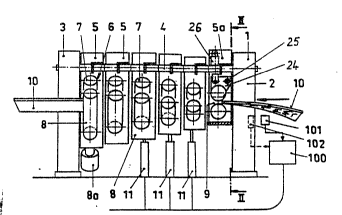
The apparatus shown in Pig. l to 3 comprises a frame l consistin~
essentially of two 8antrY like supports 2 and 3 mounted in succession to each
other at the inlet and outlet of the apparatus, and an a~le 4 extending in the
longitudinal direction of the frame and connecting the two supports 2, 3.
2~730~ ~
Oll~lS0-071 - 6 -
Tha a~le 4 forms a pivoting axle for a plurality of roller stands 5
~ollowingeuch other in auccesaion and comprising a pair 6 of rollers, con6isting
of an upper roller 7 and a lower roller B, located parallel to and spaced apart
~ro~ said upper roller.
In Pi8. 2 the roller 3tand Sa is shown with normal lines. The Foller stand
5 located at the outlet of the frame is indicated by thin lines in Pig. 2. It
is seen that the roller stsnd 5 i6 pivoted relative to the roller stand Sa around
the axle 4. It is further seen that the pivoting axle 4 is centered at the first
roller stand 5a, i.e. the measure a entered therein is equal to the measure b.
In the roller frame 5 the pivoting axle 4 i8 eccentric, i.e. the measure a is
significantly smaller than the measure b. In a similar manner, all of the roller
frames 5 are pivoted or staggerad relative to the preceding stands by a certain
angla around thc longitudinal axiG of the frama. ThiL creates between the
rollars 7, 8 a board guide channel 9 (Pig. 2) e~tending in the longitudinal
direction of ~he frame and having a twist over its entire length. The boards 10
(Pig. 1) pass through this channel, in their initial state they also have a
twist, counter in direction to the twist of the board guide channel 9. Pollowing
their passage through the board guide channel 9, the boards 10 exit in the
straightened condition, as indicated in Pig. 1.
~ ach of the roller stands 5 i6 connected with a pivot drive 11, consisting
for example of a pressure cylinder acting on a lateral arm 12 of the roller stand
5.
The pivot drives 11 associated with the individual roller framea 5 are
regulated together by means of a control 100 in a manner such that the twist
angle of the board guide channel 9 may be varied. Por this, the humidity of the
wood of the board 10 pas~ing into the board straightenin8 guide is detected by
2~ 73~ ~ ~
014150-071 ~ ~ ~
moann o~ u humidity ~anaor lOl schematically indicated in Pig. l; this value is
com~unicated to the control device lO0. Beginnin8 with an initial setting, which
in case of a predetermined wood humidity leads to straightened boards, the board
guide channel 9 i5 adjusted in the direction of a stronger twist, whenever the
humidity sensor lOl detect~ a decline in the humidity of the wood.-
A6 merely indicated in Pig. l by broken lines, a temperature sensor 10~ mayalso be provided; it detects the wood temperature of the board to be straightened
and again passes the value determined on to the control device lO0, so that the
adjustment of the twist of the board guide channel 9 may be regulated together
or separately as a function of the wood temperature determined. Whenever the
temperature sensor 102 detects a decrease in the wood temperature, a larger twist
of the board guido chanDel i8 aet.
At lsnst one rollor 8 in the roller stand 5 is equipped with 8 roller drive
8n to convey the board lO to the outlet of the apparatus.
In order to open the board 8uide channel 9, the lower part 13 of each
roller stand S and 5a may be folded down. Residual wood or board portions which
accumulate or become jammed in the board guide channel 9 may be removed simply
by folding the rollers 8 upward, whereupon the residues either drop out or may
easily be removed.
~ i8. 3 shows in a top elevation the lateral offset of the successive roller
stands 5. Pig. 3 also shows that the boards lO to be straightened in the most
important case of application are cut from a laterally flattened log 16
chiplessly by a blade 17. Pollowing their passage through a bending straighten-
ing apparatus 18 indicated in Pig. 3 schematically only, wherein their curvature
is eliminated, the boards lO immediately enter tho apparatus removing their
twist. The magnitude and direction of the twist depend essentially on the
,
2~3~ ~
0141'iO-07~ - 8 -
inclined setting of the blades 17.
Pig. 3 shows that the humidity sensor 101 may be located between the
bonding ~truightening apparatus 18 and the twist straightenine apparatus.
However, -- as indicated by broken lines in Pig. 3 -- the humidity sensor 101 may
also be located at the inlet of the boards 10 into the bending-straightenin~
apparatus 18 or at the point where the boards are cut chiplessly by the blades
17 from the log 16.
Pinally, ~ig. 3 indicates that the humidity sensor lOl may also be located
at the end of the board guide channel 9 in order to measure the humidity of the
wood. The temperature of the wood may also be determined in these locations for
the control device 100.
The modified apparatus shown in Pig. 4 and 5 differs from the apparatus
described above and illustrated in Pig. 1 to 3 essentially only by that the
individual oucce~sive roller 0tands 5 m~y be pivoted around a longitudinal framee
a~i~ approximately coinciding with the board guide channel 9. In this case the
roller stands form a ring wherein the rollers 7, 8 are bearingly supported.
These annular roller stands are moved in a sliding guide in a guide part 19 on
a circular path, the center of which is located in the longitudinal a~is of the
frame.
The roller stand 5 may a~ain be foldet up. A pressure cylinder 14 is
acting on the on the lower part 13 of the roller stand in which the roller 8 is
located, said pressure cylinder being mounted on an arm 20 connected with the
roller stand 5.
As the pivot drive in the embodiment according to Pig. 4 and 5 a worm drive
21 is provided;, it dri~es a worm se8ment 22 on the annular roller stand 5 by
means of a servomotor 23.
2~33~ ~
014150~71
A humidity sennor 101 is agsin provided in the embodiment shown in Pig. 4
and ~, tho output aignal of which i3 paased on to the control device 100. The
latter adju~to the servo~otors 23 as a function of the humidity and optionally
the temperature of the wood, to vary the twist of the board guide channel 9.
~ or the adjustment to different board thickne~ses, in the~embodiments
according to Pig. 1 to 5 in each roller stand 5 and 5a the upper roller 7 is
adjustable relative to the lower roller 8. Por this, the upper roller 7 may be
pivoted on a lateral supporta 24 around a pivot a~le 25. The pivoting sdjustment
is effected by means of a pressure cylinder 26.
In Pig. 6 and 7 another form of embodiment of the appars~us is shown. Two
conveyor belts 27, 2B e~tend from an inlet roller pair 29, 30 to an outlet roller
pair 31, 32 offset relative to the rollers 29, 30. The two co~veyor belts 27,
28 khuD exhibit u twist if viewed in their longitudinal direction; they form
b~twe~n ~hom a board guide channel 9 also provided with a twist, through which
the board 10 to be straightened i8 pas6ing. The staggered conveyor belts 27, 28
may be rubber belts with a te~tile insert or metal link chains or chain belts.
In order to prevent the board 10 passing through the board guide chaDnel
10 from pressing in the cent0r area of the conveyor belts 27, 28 the strands 33,
34 fscing each other, spart, preferably in the center range of the conveyor belt6
27, 28, cro~ned support rollers 35, 36 may be located on the reverse side of the
strands 33, 34 (Pig. 7). At least one of the two conveyor belts i8 driven, so
that the boards 10 passing through, are completely moved out of the apparatus.
Pig. 7 shows that the roller pair 31, 32 may be pivoted on the outlet side
relative to the roller pair 29, 30 on the inlet side, to vary the twist angle of
the board guide channel 9 as a function of the prevailing requirements. A pivot
drive 37 is used for the purpose: it moves the roller stand, which here is in two
2~73~1~
01~151~71 - 10 -
part~, on a circular path formed by circular recess 39.
Pig. 6 and 7 schematically fihow that here agsin the valuefi supplied by the
humidity ~ennor 101 of the wood humidity of the boards 10 are processed in the
control device 100 in order to regulate the pivot drive 37.
In this form of embodiment an adjusting drive ~0 i8 a 8ain provided on the
two roller parts 29, 30 or 31, 32, making possible in the manner described above
the adjustment of the upper rollers 29 and 31, relative to the lowPr roller 30
and 32 to different board thicknesses.
It is a8ain possible in the form of embodiment according to Pig. 6 and 7
to make the rollers 30, 32 supporting the lower conveyor belt 28 downwsrd
folding, in order to open the board guide channel 9, if broken wood debris must
be removed.
It iB common to all of the forms of e~bodimont fihown that it i~ po~iblo
to latorally ad~ust the entire frame 1, a~ indicated by the arrow6 41 in Pig. 2
and 5.
In the forms of embodiment according to Pig. 1 to 5, the successively
located roller pairs 7, 8 may also be aligned so that a curved configuration of
the board guide channel 9 is obtained. In this manner, it is possible to
straighten the board 10 in its longitudinal direction only, so that a separate
straightening apparatus 18 may be eliminated.
Pig. 6 shows an input unit 103 whereby control signals may be entered in
the control device 10 as a function of additional values in order to affect the
regulation of the board guide channel 9, in particular the feed velocity, the
type of wood, the width and the thicknefis of the board.