Note: Descriptions are shown in the official language in which they were submitted.
2073182
Apparatus and Method for Recovaring a
Tim~-Varying Si~nal in a Serial :)ata System
Field of the Invention
The present invention relatss generally to
information signal recovery, and, rnore particularly, to an
apparatus and method for recovsring information in a
10 time-varying signal which may have ogherwise boen lost
in noise.
Background of the Invention
1~
The rapid expansion of the number of cellular radio
telephones coupled with the desire to provide additional
services has prompted the development of a new standard.
The standard suggests an increasa in system capaci~y
20 ovsr the current analog system through the use of digital
modula~ion and speech coding teohniques. The standard
uses a time division mulUplex (TDM) system which splits
the current channel into six signal packets of which three
are currently in use. A packet is a burst of information
26 characterized by sequentially enco~ed symbols for the
intendad ~c~iver. The linear modulation techniqlle to
transmit the digital information within tha channel is
~/4 DQPSK (differontial quadrature phase shifted keying).
The us~ qf 7~/4 DQPSK linear mo~ul~tion in the U.S.
30 Digi~al Ccllular system provides spec~ral efficiency
allowing the use of 48.6 kbps channel data rates. ~e/4
DQPSK transmits the data information by enoodirlg
consecutiv0 pairs of bits, commonly known as symbois,
into one of four phase angles ( 7~14, +37c14) based upon
.
.
"
2 207~1~2
gray eneoding. These angles are then differen~ially
encoded producing an 8 point constellation.
Cellular systems operate in the sxisting 800 MHz
band. Radio pfop~g~lion at these frequencies is ~enerally
5 charactari~cl by three types of distortion: ~ime
dispersion distortion, multipath distortion and lognormal
distortion. Time dispersion distortion of a received
signal occurs when a transmittcd si~nal is rec~ived via
mors than one pr~p~lion path each having a differant
10 path leng~h. Measured received signals having ~ime
dispersion distortion typically have a stron~ first
component and multiple components that are generally
lower in amplitude for larger delays. Time dispersion
distor~ion of the received signal is usually found in an
15 environment wh~re a lar~e refleeting source, such as a
mountain, is present. A mobile radio in this environment
receives the signal from a fixed source transmittsr and
the delayad signal from the reflacting sourco. The time
delay b~tween the reception of the two signals results in
20 time disparsion distortion.
Multipath distortion is characterized by many rays
of the same signai havin~ ~ilieren~ ener~y levsls reaching
the receiver at the sams time. Tha number, phase and
intensity of the signals received by the receiver in a
26 multipath environment may vary over time as a result of
repositioning of the receivsr, or of the objects from
which a ~ransmitted signal is reflected. As a result, the
phase and signal level of a received signal varies over
time. This variance is rsferred ~o as "fading" of the
30 signal. The resultan~ signal stren~th and rate of changs
of signal sl-er,ylh at the receiver is predominantly
determinsd by how rapidly the receiver is moving throu~h
its environment, and the frequency of the channel being
used. For ins2anee, in the eellular frequency band, and
.
2~ 73~ ~2
when a cellular radio telephone is positioned in a vehiole
traveling at 60 mph, the signal streng~h of the received
signal can vary by approximately 20 decibels during a 5
millisecond period.
In th~ case of tima dispersion and multipath
distortion, h~o received si~nals transmitted from ~he
same source which are 180 d~grses out of phase
effectively cancal each other out. The received signal's
intensity approaches a null ànd tha rate of change of the
received signal intensity over time is rapid. Since the
raceived signal strength in~ensity is low, the modulated
information can be corrupted by noise presen~ in the
channel. A signal corrupted by noise can alter the state of
the demodulated information thereby causing the recsiver
to detect wrong information.
Lognormal distortion of a received signal occurs
when the distance beh~een the transmitting source and
the receiver increas~s ther~by causing a logarithmic
decreasa in the signal strength at the reccivor. The
distance at which lo~normal distortion begins depends
upon the transmitter's signal powsr and the reeeiv0r's
sensitivity. As the distance betwean the transmitting
source and the receiv~ increas~s, the receiv~d signal
strength intansity may dccrease to a lev~l whareby th~
moclul~te~ information is corrup~d by noise present in
the channel. As with time dispersion and multipath
distortion, a signal corrupted by noise can alter th0 state
of the demodulated information th~reby causing th~
receiver to detec~ wrong information.
Racovering a si~nal packet having tims-varying
signal intensity is feasible when the packet is relatively
short. For sxample, variation of the signal intensity over
a packet having a 0.5 millisecond duration is usually not
significant enough to alter the state of the information in
2073~82
the packe~. If the entire packet is lost in noise, the
performance of ~he system would not be substantially
degraded. The packe~ with short duration contains less
information than longer duration packets. The signal's
5 intensity is considered to be constant over the duration of
the packet while the in~or,-,alion in the packet is
recovered.
IlowevQr, systems which specify a signal packet
havin~ a relatively long duration, for example, 6.66
10 millisecond duration in ~he U.S. Digital Celiùlar systsm,
variation in the signal s~rsngth intensity can be
si~nificant. Variations can cause the signal intensity to
approach the noise floor of the channel thereby corrupting
the information in the packet thereby causing the receiYer
15 to recover wrong information.
Thus, a formidable challenge is to provide a system
for recovering information in a tirne-varying si~nal
packet having a long duration.
2~731~2
Summary of the Invention
Briefly stated, the inven~ion comprisas an apparatus
for recovering a signal packet includad in a serial data
5 signal, wherein the packet is formed of multiple
sequential symbols and a prede~ermined symbol. The
predetarmined symbol has a predetermined posltion and
value.
A receiver receives the serial data signal. A
10 direction of racovery is determined for the symbol
sequential to the pred~termined symboi. The symbol is
recovered in the determined direction. The recovery
direction is changsd be~Neen the determined direction and
a second direction. The rscovered symbol is stored.
2~73182
Brief Description of the Drawings
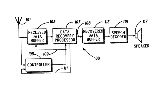
FIG. 1 is a blook diagram of a TDM r0ceiver
constructed in accordance with the present invention.
Fl(3. 2 is a biock diagram of a da~a recovery
processor includ~d in the receiver in FIG. 1.
FIG. 3A is a block dia~ram of a phase detecter
operating in a fon~ard procsssing mode included in ths
d~ta r~overy processor of. FIG 2.
FIG. 3B is a block diagram o~ a phase cleteclor
operating in a reverse processing mode included in the
data recovery processor of FIG 2.
FIG. 4A is a block diagram of a loop filter operating
in a forward processing mode included in the data
recovery processor of FIG 2.
FIG. 4B is a blook di~ram of a loop filtsr opera~in~
in a reverse procsssing mode included in the data recovery
p~cessor of FIG 2.
FIG. 5A is a block diagram of a differential decoder
oparatin~ in a forward processing mode included in the
da~a recovery processor of Fltà 2.
FIG. 5B is a block diayram of a differsntial deco~er
operating in a reverse processing mode inciuded in the
data racov~ry pr-,cessor of FIG 2. .
FIG. 6 repressnts a channel state dia~ram for a Tt: M
paeket sequence for a typical land-to-mobile station
transmission which is utilized by the present invention.
FIG. 7 is a block diagram of an equalizer included in
the data r~covery procassor of FIG. 2.
': " ' ~' .
.
- : ~
.~
2~73~82
Detailed Desoription of a Preferred Embodiment
Referring now to the clrawings, a block dia~ram of a
TDM receiver 100 shown in FIG. 1 has been construct~d in
5 accordance with the present invention. The TDM rc~eiver
overcomes the aforementioned problems by recovering the
signal packet in a forward and rsverse direction in time
depanding on the in~ensity of the signal. Groups of known
symbols called words, havirig fixed positions and values
10 within the packet, provide starting points from which the
information is recovered. Tha packet is recovered in a
direction responsive to the signal int~nsi$y over the
duration of ths packet.
Ths receivsr 100 includes an antanna 101 which
15 couples the packet intended for ~he reoeiver 100 to a
receive data buffer 103 and a mode controller 105. The
receive data buffer 103 provides a storage location for
the packet while its information is being recovered. A
control signal at line 109, genera~ecl by a mod(~ controller
20 105, is coupled to the receive data buffer 103 and a data
recovery processor 107. Tha control signal at line 109
detarmines if the information in the signal packet will be
couplsd from the receivcd data buffer 103 to the data
recovery processor 107 in a forward or reversa direction.
25 The mode controller 105 generates the control signal at
line 109 in rcsponse to the signal packe~ and a quality
signal at line 111 coupled from the data recovery
procassor 107.
The quality signai at lins 111 is a value related to
30 the quality of the signal's intensity varying with tirne
over the duration of the packet. In alternate
embodiments, the quality signal may also compris~ other
signal parameters such as the signal's phase. If th0
intensity of the receiv~d signal approaches a null durin~
. .,
8 2~73182
information recovery, the mod~ controller 105 signals the
receive data buffer 103 and the data recovery proc~ssor
107 to begin recovering the packe~ in a forward direotion
~rom one starting point un~il it reaches a null. The
information in the paoke~ continues to be recovere~ from
a n~w starting point on the other side of tha null in the
reverse direc~ion until it reaches the null. Recovering the
packet in both a forward and reverse direction in ~ime
improves ths likelihood of detecting the correct
information, thereby reducing the bi~ srror ra~e for the
received signai.
In an alternate ernbodiment, the signal packet may
be recovered in both a forward and reverse direction from
mul~ipie predet3rmined starting points to multiple
predetermined ending points~ For example, recovery of the
packet may begin at a first starting point and recover
data in the forward direction until it r~aches the ending
point. Then rccovery continuas from a second s~arting
point in a reverse clireclion until it reach~s ~he same
ending point. Recovering data from multiple startin~
points improves the bit error rate for the received signal.
An advantage of the alternate embodiment is utilized
when a null is present a~ any point in the packet~ Under
conventional forward processing condi~ions, after ths
occurance of the null, information in the packet is lost~
Usin~ the recovsry process described in the alternate
embodiment, infor.l,alion recovery may continue at o~hcr
starting points toward ending peints to reeover the
majority of data which may have otherwise bcen lost~
The data reoovery processor 107 gen0rally
e~lu~ es, detects, tracks tha carrier phase and decodes
~he, infor.llalion in ~he pack~t~ The rccovsr6d data
appearing on line 108 from the data recovery proeessor
107 is coupled to a recovered data buffer 113~ The
9 2~73~82
r~cover~d data buffer 113 is a location for storing
recovered data 102 from the packet as it is recovered.
After all thc information in a packet is rscovered, the
data is coupled from the recovered data buffer 113 t~ a
5 speech deco~er 115. The spe~ch clecoder 115 converts the
digitized signal, raceived in the encoded information
packet, into speech which may be heard throu~h a sp~ak~r
1 1 7.
NGW referring to FIG. 2, there is shown a block
10 diagram of the da~a recovery proc~ssor ~07. Tha
equalizer 203, data detec~or 209, phase detec~or 213 or
215, the loop filter 223 or 22~, the PLL switch 227 and
the NCO 231 comprise a phase lock loop (PLL) 232. The
detecl~d data from the phase lock loop is cle~odec~ and
1~ stored in the r~cover~d data buffer of FIG. 1. The loop
filter, phase dstector and differential decoder each have a
forward and r~verse processing mode. The forward
processing mode of each funotion is conventionally
implemented. The reverse processing mode of sach
20 function is performed by modifing the conventional
implemantations.
Data from the receive data buffer 103 is coupled to
a correlator 201 and an e~u~li7er 203. Th~ correlator 201
has thrsa purposes. The first purpose is to initializ~ the
25 training sequence for the equali~er 203 by sampling the
ma~nitude of the received signal. The second purpose is
to initialize the carrier phase of the received signal. The
third purpose is to determine the optimum sample rate for
clock recovery. The equalizer 203 oorrects time dalay
30 probl~ms caused by time disparsion distortion.
Predetarmined symbols within the packet are stored
in vector buffer 205. The location of tha pred~termined
symbols within the packe~ is better appreciat~ by
rsference to FIG. 6. FIG. 6 repr~sents a chann~l state
,
1~ 2~)73182
~iagram for a TDM packet sequence for a typical land-to-
mobile station transmission which the present invention
utilizes to its advantage. The TDM system splits tha
channel into three packets of information: Rx, Ry and Rz.
5 Each packst is assi~ned to a unique recaivar. The fermat
of each si~nal packet is the same. Each signal packet is
divided into six adjacant groups of symbols. A signal
packet begins with a Sync word 601, havin~ 28 symbols,
for synchronizin~ the location of thc packet within the
10 TDM system and for equalizer training. The slow
~CSoci~t~ control channel (SACC) word 603, having 12
symbols, repr~sents commands from the land sta~ion to
ths mobile station such as a hand-off required between
cells. Next are 130 symbols of data 605 followed by 12
15 symbols representing a digital voice color code ~DVCC)
607. Next are 130 symbols of data 609 followed by 12
symbols reserved (RSV) 611 for future use. The two sets
of data symbols, 605 and 609, represcnt a digitize
speech signal. The DVCC 607 differentiates behNeen two
20 cells in the TDM system having ths same frequency which
eliminates co-channel interference. The DYGC 607 is
assigned to a receiver when it entars a new cell.
The sync word 601 in the recoived signal packet, Rx
is called the desired sync word sinçe the Rx packet is
25 intended for the r~ceiver in the prefarr0d embodirnent. A
sync word 613 in the adjacsnt Ry packet is called the
~j~cent sync word. A feature of the preferred
embodiment of the presen~ invention is to use the desired
sync word 601, adjacent sync word 613 and the DVCC 607
30 as starting points for processing information in the Rx
packet in both forward and reverse directions in time.
The value and position of these starting points within
their respective packets are predetermined and known to
the receiver and are stored in vector buffer 205 of FIG. 2.
, ...
2~73182
R0turning now to Fl(;. 2, the veotor buffer 205,
storin~ the pradetermined symbois, is coupled to ~he
correlator 201 and the equalizer 203. The correlator 201
uses the prsdet0rmined symbols to determine which
packet to r~ceiv~. The equalizer 203 uses the
predet~l",ined symbols from the vector buffer 2û5 to
initializo ths equalizer procsss.
The purpose of the da~a detector 209 is to quantize
the information in the packet. A quanti~ad signal at lins
10 211, goner~ted by the data detector 209, is caupled to the
fonvard and reverse mode phase detactor 213 and 215, a
forward and reverse mode differen~ial decoder 217 and
219 and the equalizer 203. The forward and reversa mode
phase cJetaclors 213 and 215 use the equalized signal at
15 line 207 and ~hs quantized signal at line 211 to producs
an e~li",a~ of the phase error in the received si~nal. The
equaliz~r 203 uses the quantized signal at line 211 to
update the coefficients in an algorithm embodied within
the e~U~li7er 203. Based on the equalizer's performance,
20 tha equalizer will generate a quality signal at line 111
couplcd to ths mode controller 105 of FIG. 1. Responsive
to the quality si~nal at line 111, the mode controlier 105
changes the direction of rscovering the packet.
Th~ phase ~rror es~imat3 si~nal of the forward mode
2~ phase det~ctor 213 is coupled to the forward mode loop
filter 223. Likewise, the phase error esli~"ate signal of
the reverse mode phase detector 215 is coupled to the
reverse mode loop filter 225. The loop filtsrs reduce the
distortion in the phase error estimate signals and oontrol
30 the responsa time of the PLL. The filtered outputs of the
forward mode 223 and the reverse mode 225 loop filters
are coupisd to a PLL switch 2~7. The PLL switch 227,
responsive to the control signal at line 109, couples the
appropriate filtersd signal from the forward or reverse
. . .
12 20731~2
mode loop fil~er 2~3 or 225 to the conventional numeric
controlled oscillator (i~lCO) 231. The NCO 231 generates
an adjusted phase si~nal which is coupled to the equalizer
203.
The decoder switch 229, responsive to ths control
signal 109, couples the appropriate decoded signal from
either the forward 217 or reverse ~19 mode differential
clecocler to the recovered da~a buffer 113 in FIG. 1.
A block diagram of the e~iu~ er 203 is represented
in FIG. 7. The structure of the equ~ er 203 is
conventional. A feature of the preferred embodiment is in
the utilization of an adaptive algorithm processor 701.
The adaptive al~orithm processnr 701 uses information
from the mode controllsr 105 to determine tha dir~ction
of signal recovery. Other information from the data
detector 209 is used to modify tha gain stages 703
through 706 and to generate the quali~y signal at line 111
for the mode controller 105.
FIG. 3A is a block diagram of th~ conventional phasa
detector 213 opsrating in a forward processing mod~. The
purpose of the phase detector 213 is to produce an
esli~na~e of the phase error si~nal 301. Tha inputs to the
phase det~ctor 213 are the er~u~ ed signal at line 207
and the quantized signal at line 21.1. The quadrature-
phase component (Q) of the equalized signal at line 207 is
combined with the in-phase component (I) of the
quantized signal at lins 211 in mixer 303 to produca a
positiva error signal 305. Likewise, the quadrature-phase
component (Q) of $he quantized signal at line 211 is
combined with the in-phase (I) component of the equalized
signai at line 207 in mixer 307 to produce a negative
error si~nal 309. Tha positive error signal 305 and
negative error signal 309 are combined in a summer 311
to produce a phase error estimate signal 301.
.
.
13 2073~82
Flià. 3B is a block diagram o~ a phase detector
operatin~ in a reverse processing rnode. The reverse mode
phase ~le~ec~or generates a negative phase errsr estimate
signal 315 having opposite polarity to the phass error
esli",ate signai generated by the forward mode phase
datector. This is accomplished by combining a negative
unity gain signal, ~:3, wi~h the phase error estimate signal
at line 314 in mixer 31~.
FIG. 4A is a block dia~ram of the conventional loop
10 filter 223 operating in a forward proces~ing mode. The
loop filter 223 generates a ~iltered phase error signal for
the NCO to track the instantaneous phase of the receivad
signal packet. The loop ~ilter 223 also tracks the long
term frequency variation of the received signal. The loop
15 filter 223 comprises a sac~nd order infinite impulse
response filter. The phase error estimate signal at line
301 is coupled to amplifiers 401 and 403. The gain of
each amplifier ~01 and 403, determines the response time
of the loop filter 223. The output of amplifier 401 is
20 coupled to summ~r 405. Likewise, the output of amplifier
403 is coupled to summer 407. The output of summer 407
is determined from the su~ alion of the second gain
signal 404 and a symbol delay si~nal at line 409. Th~
output of summer 407 is coupled to summer 405 and
25 symb~l dclay processor 411. Th~ output of summer 405 is
coupled to the numeric controlled oscillator 231 of FIG. 2.
FIG. 4B is a block diagram of a loop filter operating
in a reverse processin~ mode. This block diagram is
identical to the block diagram of the forward processing
30 mode in FIQ. 4A except the output of the ~ilter 415 is
neg~tRd. In FIG. 48 a negative unity gain signal ~13 is
combined in a mixer 416 with the output signal of summer
418 at line 419 to genarate the filtered output signal
415. The negative unity gain signal 413 reverses the
.
2073182
14
diroction of rot~tion of thc filtered signal at line 419
before it is coupled to the NCO 231. For the reverse mode,
the instantaneos phase error of the received signal must
be tracked in the opposite direction from the forward
moda. The long term frequency variation must also be
tracked in the opposite direction ~rom the fonHard mode.
FIG. 5A is a block diagram of a differential decoder
217 oper~iing in a fo~vard processing mode. The
quantized signal 211 is coupled to a mixer 501 and symbol
delay processor 503. The symbol delay processor 503 is
coupled to the mixer 501 throu~h a oonjllgator 50~. The
mixer 501 combines ths quantized signal at line 211 and
tha delaysd and conjug~ed quantized signal at line ~07 to
produce a rotated signal at line 509. The rotated signal at
line 509 is coupled to a symbol to binary convsrter 511.
The symbol to binary converter 511 convarts the rotated
si~nal cletected in the information packet into a tw~ bit
binary pair. The two bit binary pair is coupled to the
recovered data buffer 113 of FIG. 1.
FIG. 5B is a block diagram ~f a differential decoder
operating in a reverse processing mode. The differ~nce
between the reverse mode in FIG. 5B and th~ fon~ ard mode
in FIG. 5A is the position of the conjugator 505 as shown
in FIG. 5E~. The conjugator 513 is positioned bet~,ve~n the
26 incoming quantizad signal at lina 211 and ~he mixer 515.
Moving the posilion of the conjugator 513 allows the
quantized signal to be properly deeo-~ed in the reverse
order from the forward processing mode.
Thus, a TDM rec~iver for detacting information in a
time-varying signal havin~ a iong duration has been
~isolose:l. The in~orrnation in ~he packet is processed
from predetermined starting points, in a direction
rssponsive to the intensi~y of the signal over gha dura~ion
of the packet.
. ~