Note: Descriptions are shown in the official language in which they were submitted.
SPECIFICATTON
TITLE OF THE INVENTION
Noise Reducing Structure of Slides-Cam Die
BACKGROUND OF THE INVENTION
The present invention relates to a noise reducing structure
of slide-cam die.
A general structure of conventional slide-cam die is as
shown in Fig. 7.
'Phat is, to a base plate 116 of a lower die 101, a work
positioning member 103 for positioning a work 102 is secured, and
for piercing a side wall 102a of the work 102, a passive cam 104
which slides in the direction approaching to and parting from the
side wall 102a is disposed. A piercing punch 105 is horizontally
secured to a portion of the passive cam 014 facing the side wall
102a of the work 102. Numeral 106 designates a stripper plate,
numeral 107 designates a cushion- rubber and numeral 108
designates a die bush.
To the rear side of the passive cam 104, a heel 109 is
secured and through which a rod 110 whose end is screwed into the
rear surface of the passive cam 104 inserted, thereby the passive
cam 104 is urged in a direction parting from the side wall 102a
of the work 102 by a coil spring 111.
Meanwhile, to a base plate 122 of an upper die 121, an
1
~~y~~3~~~x
actuating cam 123 is secured at a position facing the passive cam
104 of the lower die 101.
Numeral 124 designates a stripper plate, and numexal 125
designates a cushion rubber.
When piercing the side wall 102a of the work 102 by the
slide-cam die, the upper die 121 descends from a top dead point,
and while the upper face of the work 102 is pressed by the
stripper plate 124 and the actuating cam 123 is backed up by the
heel 109, an inclined actuating face 123a of the actuating cam
ZO 123 is contacted to an inclined passive face 104a of the passive
cam 104 to bring the punch 105 close to the side wall 102a of the
work 102 for piercing. The completion time of piercing is a
state of bottom dead point shown in the figure.
When the upper die 121 ascends after the completion of
piercing, the passive cam 104 slides in a direction parting from
the side wall 102a of the work 102 by an urging force of the coil
spring 111) '
Recently, noise generated at pressing causes social
problems. Noise is generated when punching metal sheets or at
pressing by the cam type die, wherein the inclined actuating face
of the actuating cam hits and drives the inclined passive face
of the passive cam: particularly, the cam type die is very noisy
and it is said that 40~ of the whole press shop noise is occupied
by noise of the cam 'type die.
2
,~. r s~ ~ ~ ~~ ~
~: a~ ~
In the above-mentioned conventional example, an inclination
angle 8 of the inclined passive face 104a of the passive cam 104
and an inclination angle 8 of the inclined actuating face 123a
of the actuating cam 123 are formed into a same angle, and a
large inclined actuating face 123a area of the actuating cam 123
and a large inclined passive face 104a area of the passive cam
104 are totally contacted with each other instantaneously to
generate large noise. Since the quiescent passive cam 104 is
suddenly moved forcik~ly, the punch 105 and the stripper plate 106
installed on the passive cam 104 and the cushion rubber 107
starts to vibrate to cause noises.
In view of the above-mentioned circumstances, the present
invention provides a noise-reducing structure of slide-cam die,
wherein in the slide-cam die comprising, for reducing noise in
the slide-cam die as much as possible, a passive cam having an
inclined passive face of a fixed inclination angle a, and an
actuating cam having an inclined actuating face of the same
inclination angle a as that of the inclined passive face of the
passive cam, and contacting the inclined actuating face of the
actuating cam to the inclined passive face of the passive cam to
drive the actuating cam for pressing a work; a roller is disposed
rotatably at the side of the passive cam, and a speed control cam
plate having, at a location of the actuating cam facing the
roller, a cam face having, at a position where an upper die
3
~.l ' c ~ <~ 9 ~~5:
~'~ '~L~ ~ ~ ~ ~ ~.~ r~
contacts to the roller at the beginning of descending, a low-
speed inclination angle (3 which is larger than the inclination
angle a of the inclined faces of the passive cam and the
actuating cam and close to a right angle, and a succeeding
medium-speed inclination angle y which is slightly larger than
the inclination angle a of the inclined faces of the passive cam
and the actuating cam is disposed such that, after the medium-
speed inclination angle y of the cam plate has contacted to the
roller, the inclined actuating face of the actuating cam and the
inclined passive face of the passive cam are brought in contact
with each other to shift the passive cam to the low, medium and
pressing speeds continuously for pressing.
The present invention is that, since the roller is disposed
rotatably at the side of the passive cam, and a speed control cam y .
plate having, at a location of the actuating cam facing the
roller, a cam face having, at a position where an upper die
contacts to the roller at the beginning of descending, a low-
speed inclinatior. angle (3 which is larger than the inclination
angle a of the inclined faces of the passive cam and the
actuating cam and close to a right angle, and a succeeding
medium-speed inclination angle y which is slightly larger than
the inclination angle a of the inclined faces of the passive cam
and the actuating cam is disposed such that, after the medium-
speed inclination angle ~' of the cam plats has contacted to the
4
roller, the inclined actuating face of the actuating cam contacts
to the inclined passive face of the passive cam for pressing
work, noise is reduced remarkably.
HRIEF DESCRIPTION OF Td~iE DRAWINGS
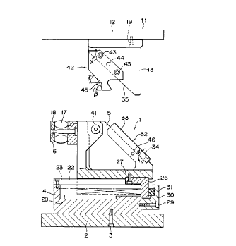
Fig. 1 is a side view of slide-cam die of one specific
embodiment of the present invention which are at a top dead '
point,
Fig. 2 is a front view of a lower die of Fig. 1,
Fig. 3 is a side view showing a state, wherein an upper die
descends and a low-speed inclination angle portion of a speed
control cam plate installed on an actuating cam starts to contact
to a roller disposed on a passive cam,
Fig. 4 is a side view showing a state, wherein an upper die
descends and a medium-speed inclination angle portion of a speed
control cam plate contacts to a roller,
Fig. 5 is a side view showing a-state, wherein an upper die
descends, an inclined actuating face of an actuating cam contacts
to an inclined passive face of a passive cam and a cam face of
a speed control cam plate and a roller are detached,
Fig. 6 is a side view showing a state of bottom dead point,
wherein an upper die descends further, and
Fig. 7 is a longitudinal sectional view of conventional
slide-cam die.
5
p9 ~ ~d ~ ~%~
DETAILED DESCRIPTION OF THE PREFERRED EMBODIMENTS
The present invention is particularly described in the
following based upon a specific embodiment shown in Fig. 1
through Fig. 6 of the accompanying drawings.
Fig. 1 is a side view showing a state of top dead point of
slide-cam die. Fig. 2 is a front view of a lower di~.
A guide stand 4 is secured to an upper face of a base plate
2 of the lower die 1 by means of bolts 3, and a passive cam 5 is
disposed slidably arid horizontally on the guide stand 4.
Meanwhile, an actuating cam 13 is secured to a lower face
of an upper die 11 by means of bolts 19 so as to face the passive
cam 5 of the lower die 1.
To a front face of the passive cam 5, a piercing punch 16
is secured horizontally, and at an end point of the punch 16 a
stripper plate 18 is disposed via a cushion rubber 17. Though
not shown, in front of the punch 26, as described in the
conventional example of Fig. 7, a work is placed on a positioning
member, and at a piercing position of the positioning member a
die bush is buried. Hereinafter, for simplification of the
description working members such as the punch 16 are not shown.
It goes without saying that the working members responsive
to workings such as notching, forming and the like other than
piercing, are disposed on the front face of the passive cam 5.
Though the passive cam 5 slides on the guide stand 4, guide
6
i~ e~ ~ ~~
projections 21 are projected symmetrically from the guide stand
4, and a wear plate 22 is secured to its upper face by means of
bolts 23. Support plates 24 are secured to both sides of the
passive cam 5 by means of bolts 25 s~o as to embrace the guide
projections 21.
A spring shoe 26 is secured to a lower rear face of the
passive cam 5, and one end of a coil spring 28 provided at the
center portion of the guide stand 4 is contacted to the spring
shoe 26 to urge the passive cam 5 backward.
A rear face of the spring shoe 26 urged by the coil spring
28 is secured to the rear face of the guide stand 4 by means of
bolts 29, and is contacted to a cushion rubber 31 held by a hold
plate 30.
On an upper rear face of the gassive cam 5, an inclined
passive face 32 having a fixed inclination angle a is formed by
securing a wear plate 33 by means of bolts 34. The inclination
angle a is usually set to 45°. -
Meanwhile, also on the actuating cam 13 of the upper die 11,
an inclined actuating face 35 which contacts to the inclined
passive face 32 of the passive cam 5 and has the same inclination
angle a is formed.
The slide-cam die of the present invention is a noise-
reducing structure. For this end, it is necessary to avoid
instantaneous contact between the inclined passive face 32 of the
7
passive cam 5 and the inclined actuating face 35 of the actuating
cam 13, and the passive cam 5 should move slowly at the beginning
then move at a suitable working speed and slowly at the end,
besides the moving speed of the passive cam should change
gradually.
A roller 41 is disposed rotatabl;y at the upper side of the
passive cam 5 and a speed control cam plate 42 is secured to the
actuating cam 13 of the upper die 11 facing the roller 41 by
means of bolts 43, knock pins 44 is driven in 'after adjusting the
position accurately.
The speed control cam plate 42 includes a cam face 45
consisting of a low-speed inclination angle (3, which is larger
than the inclination angle a of the inclined faces 32, 35 of the
passive cam 5 and the actuating cam 11 and close to a right
angle, and is formed at the lower side or a position which
contacts to the roller 41 at the beginning, and a medium-speed
inclination angle y, which is slightly larger than the
inclination angle a of the inclined Faces 32, 35 of the passive
cam 5 and the actuating cam 11 and is formed successively at the
upper side thereof. Connection between the low-speed inclination
angle a and the medium-speed inclination angle y takes the form
of arc and is connected smoothly. The low-speed inclination
angle ~ is 85° and the medium-speed inclination angle y is 47°.
When the inclination angle is large, the passive cam 5 moves
8
only a little horizontally at descending of the actuating cam 13,
and when the inclination angle is small, the passive cam 5 moves
largely horizontally at a slightly descending of the actuating
cam 13.
Though a safety pin 46 is projected horizontally at the rear
side of the passive cam 5, this is de;~cribed later.
The operation of the slide-cam die comprising speed control
cam plate 42 is described.
Fig. 1 shows a state of top dead point.' The speed control
cam plate 42 disposed on the actuating cam 13 of the upper die
11 is arranged such that, its cam face 45 faces the roller .41
disposed on the passive cam 5 of the lower die 1. The spring
shoe 26 on the lower rear face of the actuating cam 5 is urged
by the coil spring 28 at its rear face and contacted to the
cushion rubber 31. When a press machine is driven, the upper die
11 starts to descend from this state.
The upper die I1 descends and a~s shown in Fig. 3, the low-
speed inclination angle ~ portion of the cam face 45 of the speed
control cam plate 42 is contacted to the roller 41 of the passive
cam 5. Though the passive cam 5 is urged backward by the coil
spring 28, since the speed control cam glate 42 has'contacted to
the roller 41, it starts to move forward against this. At this
time, the inclined actuating face 35 of the actuating cam l3 and
the inclined passive face 32 of the passive cam 5 are still not
9
,,.,
in contact . Since the low-speed inclination angle (3 85 ° , passive
cam 5 starts to move very slowly and noise is hardly generated.
When the upper die 11 descends subsequently, as shown in
Fig. 4, the medium-speed inclination angle y portion of the speed
control cam plate 42 is contacted to the roller 41, and since the
medium-speed inclination angle y is 47 ° , the speed of the passive
cam 5 becomes faster than the case wherein the roller 41 is
contacted to the low-speed inclination angle a. Even when the
speed becomes faster, it happens after starting to move slowly
so that noise is not generated and the punch 16, cushion rubber
17, stripper plate 18 and so on do not vibrate. Also in this
case, the inclined actuating face 35 of the actuating cam 13 and
the inclined passive face 32 of the passive cam 13 are still not
in contact.
When the upper die 11 descends further subsequently and the
contact between the speed control cam plate 42 and the roller 41
is ended, the inclined actuating face 35 of the actuating cam 13
starts to contact to the inclined passive face 32 of the passive
cam 5. It moves smoothly to the inclined faces 35, 32 of the
actuating cam 13 and the passive cam 5 from the medium-speed
inclination angle y portion, so that noise is not generated.
Fig. 5 shows a state, wherein the medium-speed inclination angle
y portion of the speed control cam plate 42 finishes contact with
the roller 41, the inclined actuating face 35 of the actuating
cam 13 contacts to the inclined passive face 32 of the passive
cam 5, and the cam face 45 of the speed control cam plate 42
detaches from the roller 41.
Fig. 6 shows a state of bottom dead point where the upper
die 11 has descended still further. Though not shown, the punch
16 has finished piercing the work. Naturally, the inclined
actuating face 35 of the actuating cam 13 continues to contact
to the inclined passive face 32 of the passive cam 5 to generate
a pressure force suitable for pressing, and the cam face 45 of
the speed control cam plate 42 is not in contact with the roller
41.
As such, in the slide-cam die of the present invention, the
speed of the passive cam 5 moves continuously from the low speed
to the medium and pressing speeds, so that noise is not
generated.
Next, the upper die 11 ascends and operate reversely to the
aforesaid operation.
That is, the upper die 11 starts to ascend from the state
shown in Fig. 6. In the state of bottom,dead point, though the
safety pin 46 is engaged to a safety cam face ~47 which is
projected at the lower rear side of the speed control cam plate
42, when the upper die 11 ascends, the safety cam face 47 engages
to the safety pin 46 and forcibly retreats the passive cam 5 for
11
safety. The safety pin 46 is designed to break when the passive
cam 5 does not retreat by this embodiment.
When the upper die 11 ascends to the state shown in Fig. 5,
the inclined actuating face 35 of the actuating cam 13 and the
inclined passive face 32 of the passive cam 5 are still in
contact, and though the cam face 45 of the speed control cam
plate 42 urges the passive cam 5 backward by the coil spring 28,
it is yet not contacted to the roller 41.
When the upper die 11 ascends subsequently, at the same time
as the inclined actuating face 35 of the actuating cam 13
detaches from the inclined passive face 32 of the passive cam.5,
the medium-speed inclination angle y portion of the speed control
cam plate 42 starts to contact to the roller 41. When the upper
die 11 ascends further, as shown in Fig. 4, the actuating cam
face 35 of the actuating cam 13 detaches further from the
inclines passive face 32 of"the passive cam 5. At the same time
as the inclined actuating face 35 of the actuating cam 13
detaches from the inclined passive face 32 of the passive cam 5,
the medium-speed inclination angle y portion of the cam face 45
of the speed control cam plate 42 contacts to the roller 41, and
the speed of the passive cam 5 changes smoothly, so that it _
causes no noise.
When the upper die 11 ascends further, as shown in Fig. 3,
the roller 41 contacts to the low-speed inclination angle (3
12
portion of the speed control cam plate 42 and the passive cam 5
is decelerated.
When the upper die 11 ascends subsequently, as shown in Fig.
1, the cam face 45 of the speed control cam plate 42 is detached
from the roller 41, arid though the spring shoe 2s of the passive
cam 5 is contacted to the cushion rubber 31, since the passive
cam 5 has been decelerated by the speed control cam plate 42,
impact noise a.s never generated.
In the slide-cam die, the speed of rthe passive cam 5
gradually slows down even at ascending.
In the above-mentioned embodiment, though the cam face of
the speed control cam plate consisting of the low-speed
inclination angle and the medium-speed inclination angle has been
described, the present invention is not limited thereto, it may
be formed into a cam face of a mufti-stage inclination angle or
a circular cam face as required.
In the above-mentioned embodiment, though an example in
which the roller is disposed on the passive cam and the speed
control cam plate is disposed on the actuating cam has been
described, the speed control cam plate may be disposed on the
passive cam and the roller may be disposed on the actuating cam.
The present invention is, as described above, directed to
a noise reducing structure of the slide-cam die, wherein in the
slide-cam die comprising, a passive cam having an inclined
13
passive face of a fixed inclination angle a, and an actuating cam
having an inclined actuating face of the same inclination angle
a as that of the inclined passive face of the passive cam, and
contacting the inclined actuating face of the actuating cam to
the inclined passive face of the passive cam to drive the passive
cam for pressing a work; a roller is disposed rotatably at the
side of the passive cam, and a speed control cam plate having,
at a location of the actuating cam facing the roller, a cam face
having, at a position where an upper die contacts to the roller
at the beginning of descending, a low-speed inclination angle a
which is larger than the inclination angle a of the inclined
faces of the passive cam and the actuating cam and close to a
right angle, and a succeeding medium-speed inclination angle y
which is slightly larger than the inclination angle a of the
inclined faces of the passive cam and the actuating cam, is
disposed such that, after the medium-speed inclination angle y
of the cam plate has contacted to- the roller, the inclined
actuating face of the actuating cam contacts to the inclined
passive face of the passive cam for pressing work, whereby
instantaneous contact between the inclined passive face of the
passive cam and 'the inclined actuating face of the actuating cam
is avoided, the passive cam is moved slowly at the beginning to
reach the suitable descending speed and also moved slowly at the
end to reduce noise, and further, vibration of processing members
14
such as a punch is lessened as much as possible to reduce noise
to about 10~ of the conventional noise.