Language selection

Search

Patent 2073217 Summary

Third-party information liability

Some of the information on this Web page has been provided by external sources. The Government of Canada is not responsible for the accuracy, reliability or currency of the information supplied by external sources. Users wishing to rely upon this information should consult directly with the source of the information. Content provided by external sources is not subject to official languages, privacy and accessibility requirements.

Claims and Abstract availability

Any discrepancies in the text and image of the Claims and Abstract are due to differing posting times. Text of the Claims and Abstract are posted:

  • At the time the application is open to public inspection;
  • At the time of issue of the patent (grant).
(12) Patent: (11) CA 2073217
(54) English Title: ROTARY PIPE AND FIXED CHANNEL AUGER WITH INTERMEDIATE OUTER SUPPORTING ELEMENTS
(54) French Title: AUGE A TUBE ROTATIF ET CANAL FIXE AVEC ELEMENTS DE SOUTIEN INTERMEDIAIRE EXTERNES
Status: Expired and beyond the Period of Reversal
Bibliographic Data
(51) International Patent Classification (IPC):
  • B65G 33/24 (2006.01)
  • B65G 33/14 (2006.01)
(72) Inventors :
  • BERTOLA, ROBERTO (Italy)
  • MORONI, DANTE (Italy)
(73) Owners :
  • ROBERTO BERTOLA
  • DANTE MORONI
(71) Applicants :
  • ROBERTO BERTOLA (Italy)
  • DANTE MORONI (Italy)
(74) Agent: MARKS & CLERK
(74) Associate agent:
(45) Issued: 2003-06-17
(22) Filed Date: 1992-07-06
(41) Open to Public Inspection: 1993-01-24
Examination requested: 1999-02-17
Availability of licence: N/A
Dedicated to the Public: N/A
(25) Language of filing: English

Patent Cooperation Treaty (PCT): No

(30) Application Priority Data:
Application No. Country/Territory Date
MI91A-02031 (Italy) 1991-07-23

Abstracts

English Abstract


A rotary pipe and fixed channel auger with
intermediate outer supporting elements comprises
alternated portions of a rotary spiral, within the
fixed outer channel and, respectively, of a fixed
spiral clamped within an outer pipe which turns
rigidly therewith, the portions of rotary pipe
having preferably a like length and bearing on
outer supporting elements which substantially com-
prise pairs of centering rollers connected by
shafts which are parallel to the axis of the spiral


Claims

Note: Claims are shown in the official language in which they were submitted.

11
The embodiments of the invention in which an exclusive property
or privilege is claimed are defined as follows:
1. A fixed channel and rotary pipe auger with outer intermediate
supporting means, said auger comprising a rotary axis rigidly
supporting spiral means, said spiral means including a plurality of
first spiral portion means encompassed by fixed outer channel means and
second spiral portion means rigid with rotary outer pipe portion means,
said rotary outer pipe portion means being coaxial with said fixed
outer channel means so as to define a single tubular containing body
and being supported rotatably on said intermediate supporting means,
said intermediate supporting means comprising pairs of centering roller
means connected by shaft means parallel to said rotary axis.
2. An auger according to claim 1, wherein said outer pipe portion
means have an outer surface provided, at said centering roller means,
with a plurality of circular low friction sliding tracks.
3. An auger according to claim 1 or 2, wherein said pairs of
centering roller means comprise three pairs of rollers means
symmetrically spaced on a circumference of said rotary outer pipe
portion means.

12
4. An auger according to claim 2, wherein said roller means comprise
roller elements having portions provided with edges adapted to abut
against an inner surface of said tracks.
5. An auger according to any one of claims 1 to 4, wherein said
shaft means connecting said roller means are supported by a supporting
frame welded to said fixed outer channel means.

Description

Note: Descriptions are shown in the official language in which they were submitted.


2 2~~3~i7
BACKGROUND OF THE INVENTION
The present invention relates to a rotary
pipe and fixed channel auger with intermediate outer
suppo~°ting elements.
As is known there are at present used sever-
al industrial open conveying systems of the belt,
roller, bucket, truck,~chain type, which are affect-
ed by noise and difficult maintenance problems, in
addition to having a comparatively high installation
cost.
Comparatively noiseless conveying systems,
which do not cause any alterations of the materials,
are the so-called closed systems, including the
augers, or Archimedean screws, including a helical
surface which turns inside a pipe which may be in-
tegral therewith or be separated therefrom.
They are conventionally used in several
systems for conveying solid materials, either in a
granular or liquid condition, or for mixing differ-
ent materials.
Also known is anauger sorter, in which the
auger is fixed and has a vertical axis.
In this device, the auger operates as a
slightly slanted fixed channel, for discharging at

2a'~3~1~
3
a low speed loose materials and the like.
The conveying augers usually comprise two
different types of assemblies: the first includes
the spiral which is separated from the perimetrical
pipe and is called, perhaps not properly, auger; the
second has its full or partial spiral affixed with-
in the rotary pipe and is usually called "rotary
tube"
The industrial type of auger is mainly used
for horizontal conveyance.
Rarely it is also used for conveying mate-
rials on slight slopes, these materials consisting
of loose solid materials or dense liquids. For con-
veying granular solid materials there are convention-
ally used vertical augers.
The conveying device is loaded at any set
region of the path, and it is likewise unloaded, by
opening the bottom of the channel. The drive is pro-
vided by a longitudinal central shaft, of hollow
construction, usually made of steel and supported
by supporting elements spaced from one another by
2.5-3.5 m.
Several types of spirals are used and, more
specifically, an iron sheet spiral, a ribbon or belt

4 2~~3~~~
spiral, a blade spiral including a plurality of blades
operating as the blade elements of a propeller, and
allowing the advancing speed of the material to be
changed by changing the angles of the blades, as well
as a fixed-spiral auger made of a manganese steel
alloy for conveying materials having high abrading
properties.
Only by using comparatively great diameter
shafts it has been possible to make great length ~f
augers, having a length up to 50 m; the diameter of
the shaft being increased frorn 140 to 300 mm and that
of the outer channel from 400 to 630 mm, the support-
ing elements being spaced by 7-8 up to a maximum of
m and, for greater spacings, several series ar-
ranged augers must be provided.
These prior auger devices, however, are af-
fected by great problems: in fact, the volumetric
mass of material which can be conveyed, that is the
conveying capability of the auger is greatly reduced,
the power required for driving the auger increasing
proportionately to the resistances to the movements
and, simultaneously, the device has a poor reliabi-
lity and requires frequently mantenance operations.
Independently from its size, the spiral is

2~°~3217
interrupted at each supporting elements, with conse-
quent great difficulties from the conveyance stand-
point, and with the possibility of jams, as powder
or paste materials are conveyed.
Moreover, the intermediate supporting ele-
ments are subjected to a high corrosion and, because
of friction, the temperature can excessively increase
so as to cause fires or explosions, whereas some
types of chemical products tend to cure under high
temperatures, so as to cause the above mentioned
jams.
In order to reduce the maintenance diffi-
culties, prior auger devices include a half-cut bear-
ing element, which can be opened in order to access
the support member without disassembling the auger
and, usually, several augers are series arranged
with consequent greater costs for the motors, elec-
tric controls and so on.
SUMMARY OF THE INVENTIOf~
Thus, the aim of the present invention is
to solve the above disclosed problems and overcome
the drawbacks affecting the intermediate supporting
elements at present provided for supporting auger
assemblies used for industrial closed conveying sys-

2~~321~
terns.
Within the scope of the above aim, a main
object of the present invention is to provide a sup-
porting element which allows the conveyance capabili-
ty of the auger to be increased, without increasing
the size of the outer channel and the diameter of
the driving shaft.
Another object of the present invention
is to obtain the above-mentioned results without in-
creasing the labour necessary for assembling the
auger systems or the cost thereof.
Yet another object of the invention is to
provide an auger apparatus for conveying materials
which has a very reduced power consume, and a very
high conveyance capability.
According to one aspect of the.~resent in-
vention, the above mentioned aim and objects, as
well as yet other objects, which will become more
apparent hereinafter, are achieved by a fixed chan-
nel and rotary pipe auger with outer intermediate
supporting elements, characterized in that said
auger comprises alternated portions of a rotary
spiral within the fixed outer channel and, respect-
ively, of a fixed spiral clamped within an outer

CA 02073217 2002-08-06
pipe turning rigidly with said fixed spiral.
In another embodiment, the present invention provides a
fixed channel and rotary pipe auger with outer intermediate supporting
means, the auger comprising a rotary axis rigidly supporting spiral
means, the spiral means including a plurality of first spiral portion
means encompassed by fixed outer channel means and second spiral portion
means rigid with rotary outer pipe portion means, the rotary outer pipe
portion means being coaxial with the fixed outer channel means so as to
define a single tubular containing body and being supported rotatably on
the intermediate supporting means, the intermediate supporting means
comprising pairs of centering roller means connected by shaft means
parallel to the rotary axis.
BRIEF DESCRIPTION OF THE DRAWINGS
Further characteristics and advantages of the fixed channel
and rotary pipe auger, provided with outer intermediate supporting
elements, according to the present invention, will become more apparent
hereinafter, from the following detailed disclosure of some preferred
embodiments thereof, which are illustrated by way of a merely
indicative, but not limitative, example in the figures of the
accompanying drawing, where:
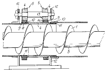
Figure 1 illustrates a side view of the auger, in which the
rotary pipe has been shown partially cross-sectioned: and
Figure 2 is a front cross-sectional view of the auger
according to the present invention.
DESCRIPTION OF THE PREFERRED EMBODIMENT
With reference to the figures of the accompanying drawings.
the fixed channe l and rotary pipe auger according to the invention
comprises a plurality of alternated portions of a rotary spiral 1 within
an outer fixed channel 2 and, respectively, of a fixed spiral 3 which is
clamped within an outer

~a~3~~~
pipe 4 which can turn rigidly with the fixed spiral.
According to a preferred embodiment of the
invention, the rotary pipe portions 4 have a like
length and bear on outer supporting elements 5.
Said supporting elements 5 are substantial-
1y formed by pairs of centering rollers 6, vahich are
connected by shafts 7 parallel to the axis 8 of the
spiral 3.
In a further preferred embodiment, the pairs
of rollers 6 are three in number, and are symmetric-
ally spaced on the circumference of the pipe 4.
At the centering rollers 6, the outer sur-
face of the rotary pipes 4 is provided with guides
or tracks 9 having a circular crown arrangement.
In particular, the tracks 9 are specifical-
1y processed in order to provide good sliding pro-
perties.
The fixed channel portions 2 and rotary
pipes 4, alternatively, can be made as an outer
jacket, at the end superimposed portions thereof,
so as to define a single containing tubular body.
The mutual sealing of said fixed channel
portions 2 and rotary pipes 4 is assured by suitable
gaskets 11 made of any suitable abrasion resisting

20~321~
material.
The outer roller supporting shafts 7 are
supported by a supporting frame 12 which is welded
to the fixed outer channel 2.
The rollers 6 have the rims thereof provid-
ed with an edge portion 14 adapted to abut on the
inner face of the sliding guides 9.
From the above disclosure and the figures
of the accompanying drawings, it should be apparent
that the invention fully achieves the intended aim
and objects.
In particular, there are solved the tech-
nical and economic problems of prior supporting ele-
ments which are at present used inside the channels,
with respect to the conveyance capability of the
auger, the resistance to the movement, reliabili-
ty and maintenance.
Moreover, there are enhanced the conveyance
properties for loose materials such as cereals,
meals, cement powders, as well as wood meals and
pastes.
In fact, owing to the invention, it is pos-
Bible to achieve, since the cost increase of 'the new
supporting elements is counterbalanced by the small-

l0 2U'~3~17
er diameter of the channel, with a consequent small-
er consume of materials, the high longitudinal ex-
tensions necessary in the processing industries,
without increasing the cost for unit of length.
While the invention has been illustrated
and disclosed with reference to preferred embodiments
thereof, it should be apparent that the disclosed
embodiments are susceptible to several modifications
and variations all of which will come within the
spirit and scope of the appended claims.

Representative Drawing
A single figure which represents the drawing illustrating the invention.
Administrative Status

2024-08-01:As part of the Next Generation Patents (NGP) transition, the Canadian Patents Database (CPD) now contains a more detailed Event History, which replicates the Event Log of our new back-office solution.

Please note that "Inactive:" events refers to events no longer in use in our new back-office solution.

For a clearer understanding of the status of the application/patent presented on this page, the site Disclaimer , as well as the definitions for Patent , Event History , Maintenance Fee  and Payment History  should be consulted.

Event History

Description Date
Time Limit for Reversal Expired 2006-07-06
Inactive: IPC from MCD 2006-03-11
Letter Sent 2005-07-06
Inactive: Entity size changed 2004-07-26
Grant by Issuance 2003-06-17
Inactive: Cover page published 2003-06-16
Inactive: Entity size changed 2003-04-01
Pre-grant 2003-03-25
Inactive: Final fee received 2003-03-25
Notice of Allowance is Issued 2002-11-18
Letter Sent 2002-11-18
Inactive: Approved for allowance (AFA) 2002-11-04
Amendment Received - Voluntary Amendment 2002-08-02
Inactive: S.30(2) Rules - Examiner requisition 2002-02-07
Amendment Received - Voluntary Amendment 1999-08-31
Inactive: Application prosecuted on TS as of Log entry date 1999-03-05
Letter Sent 1999-03-05
Inactive: Status info is complete as of Log entry date 1999-03-05
All Requirements for Examination Determined Compliant 1999-02-17
Request for Examination Requirements Determined Compliant 1999-02-17
Application Published (Open to Public Inspection) 1993-01-24

Abandonment History

There is no abandonment history.

Maintenance Fee

The last payment was received on 2003-03-19

Note : If the full payment has not been received on or before the date indicated, a further fee may be required which may be one of the following

  • the reinstatement fee;
  • the late payment fee; or
  • additional fee to reverse deemed expiry.

Patent fees are adjusted on the 1st of January every year. The amounts above are the current amounts if received by December 31 of the current year.
Please refer to the CIPO Patent Fees web page to see all current fee amounts.

Fee History

Fee Type Anniversary Year Due Date Paid Date
MF (application, 5th anniv.) - small 05 1997-07-07 1997-06-19
MF (application, 6th anniv.) - small 06 1998-07-06 1998-07-02
Request for examination - small 1999-02-17
MF (application, 7th anniv.) - small 07 1999-07-06 1999-07-05
MF (application, 8th anniv.) - small 08 2000-07-06 2000-06-30
MF (application, 9th anniv.) - small 09 2001-07-06 2001-07-03
MF (application, 10th anniv.) - small 10 2002-07-08 2002-07-08
MF (application, 11th anniv.) - standard 11 2003-07-07 2003-03-19
Final fee - standard 2003-03-25
MF (patent, 12th anniv.) - small 2004-07-06 2004-07-06
Owners on Record

Note: Records showing the ownership history in alphabetical order.

Current Owners on Record
ROBERTO BERTOLA
DANTE MORONI
Past Owners on Record
None
Past Owners that do not appear in the "Owners on Record" listing will appear in other documentation within the application.
Documents

To view selected files, please enter reCAPTCHA code :


To view images, click a link in the Document Description column. To download the documents, select one or more checkboxes in the first column and then click the "Download Selected in PDF format (Zip Archive)" or the "Download Selected as Single PDF" button.

List of published and non-published patent-specific documents on the CPD .

If you have any difficulty accessing content, you can call the Client Service Centre at 1-866-997-1936 or send them an e-mail at CIPO Client Service Centre.


Document
Description 
Date
(yyyy-mm-dd) 
Number of pages   Size of Image (KB) 
Abstract 1993-11-26 1 10
Claims 1993-11-26 2 33
Description 1993-11-26 9 172
Drawings 1993-11-26 2 43
Claims 2002-08-05 2 42
Description 2002-08-05 9 198
Representative drawing 2002-11-03 1 17
Representative drawing 1999-03-10 1 23
Acknowledgement of Request for Examination 1999-03-04 1 178
Commissioner's Notice - Application Found Allowable 2002-11-17 1 163
Maintenance Fee Notice 2005-08-30 1 172
Correspondence 2003-03-24 1 27
Fees 2004-07-05 1 31
Fees 1996-07-02 1 59
Fees 1995-06-21 1 63
Fees 1994-06-22 1 44