Sélection de la langue

Search

Sommaire du brevet 2073217 

Énoncé de désistement de responsabilité concernant l'information provenant de tiers

Une partie des informations de ce site Web a été fournie par des sources externes. Le gouvernement du Canada n'assume aucune responsabilité concernant la précision, l'actualité ou la fiabilité des informations fournies par les sources externes. Les utilisateurs qui désirent employer cette information devraient consulter directement la source des informations. Le contenu fourni par les sources externes n'est pas assujetti aux exigences sur les langues officielles, la protection des renseignements personnels et l'accessibilité.

Disponibilité de l'Abrégé et des Revendications

L'apparition de différences dans le texte et l'image des Revendications et de l'Abrégé dépend du moment auquel le document est publié. Les textes des Revendications et de l'Abrégé sont affichés :

  • lorsque la demande peut être examinée par le public;
  • lorsque le brevet est émis (délivrance).
(12) Brevet: (11) CA 2073217
(54) Titre français: AUGE A TUBE ROTATIF ET CANAL FIXE AVEC ELEMENTS DE SOUTIEN INTERMEDIAIRE EXTERNES
(54) Titre anglais: ROTARY PIPE AND FIXED CHANNEL AUGER WITH INTERMEDIATE OUTER SUPPORTING ELEMENTS
Statut: Périmé et au-delà du délai pour l’annulation
Données bibliographiques
(51) Classification internationale des brevets (CIB):
  • B65G 33/24 (2006.01)
  • B65G 33/14 (2006.01)
(72) Inventeurs :
  • BERTOLA, ROBERTO (Italie)
  • MORONI, DANTE (Italie)
(73) Titulaires :
  • ROBERTO BERTOLA
  • DANTE MORONI
(71) Demandeurs :
  • ROBERTO BERTOLA (Italie)
  • DANTE MORONI (Italie)
(74) Agent: MARKS & CLERK
(74) Co-agent:
(45) Délivré: 2003-06-17
(22) Date de dépôt: 1992-07-06
(41) Mise à la disponibilité du public: 1993-01-24
Requête d'examen: 1999-02-17
Licence disponible: S.O.
Cédé au domaine public: S.O.
(25) Langue des documents déposés: Anglais

Traité de coopération en matière de brevets (PCT): Non

(30) Données de priorité de la demande:
Numéro de la demande Pays / territoire Date
MI91A-02031 (Italie) 1991-07-23

Abrégés

Abrégé anglais


A rotary pipe and fixed channel auger with
intermediate outer supporting elements comprises
alternated portions of a rotary spiral, within the
fixed outer channel and, respectively, of a fixed
spiral clamped within an outer pipe which turns
rigidly therewith, the portions of rotary pipe
having preferably a like length and bearing on
outer supporting elements which substantially com-
prise pairs of centering rollers connected by
shafts which are parallel to the axis of the spiral

Revendications

Note : Les revendications sont présentées dans la langue officielle dans laquelle elles ont été soumises.


11
The embodiments of the invention in which an exclusive property
or privilege is claimed are defined as follows:
1. A fixed channel and rotary pipe auger with outer intermediate
supporting means, said auger comprising a rotary axis rigidly
supporting spiral means, said spiral means including a plurality of
first spiral portion means encompassed by fixed outer channel means and
second spiral portion means rigid with rotary outer pipe portion means,
said rotary outer pipe portion means being coaxial with said fixed
outer channel means so as to define a single tubular containing body
and being supported rotatably on said intermediate supporting means,
said intermediate supporting means comprising pairs of centering roller
means connected by shaft means parallel to said rotary axis.
2. An auger according to claim 1, wherein said outer pipe portion
means have an outer surface provided, at said centering roller means,
with a plurality of circular low friction sliding tracks.
3. An auger according to claim 1 or 2, wherein said pairs of
centering roller means comprise three pairs of rollers means
symmetrically spaced on a circumference of said rotary outer pipe
portion means.

12
4. An auger according to claim 2, wherein said roller means comprise
roller elements having portions provided with edges adapted to abut
against an inner surface of said tracks.
5. An auger according to any one of claims 1 to 4, wherein said
shaft means connecting said roller means are supported by a supporting
frame welded to said fixed outer channel means.

Description

Note : Les descriptions sont présentées dans la langue officielle dans laquelle elles ont été soumises.

2 2~~3~i7
BACKGROUND OF THE INVENTION
The present invention relates to a rotary
pipe and fixed channel auger with intermediate outer
suppo~°ting elements.
As is known there are at present used sever-
al industrial open conveying systems of the belt,
roller, bucket, truck,~chain type, which are affect-
ed by noise and difficult maintenance problems, in
addition to having a comparatively high installation
cost.
Comparatively noiseless conveying systems,
which do not cause any alterations of the materials,
are the so-called closed systems, including the
augers, or Archimedean screws, including a helical
surface which turns inside a pipe which may be in-
tegral therewith or be separated therefrom.
They are conventionally used in several
systems for conveying solid materials, either in a
granular or liquid condition, or for mixing differ-
ent materials.
Also known is anauger sorter, in which the
auger is fixed and has a vertical axis.
In this device, the auger operates as a
slightly slanted fixed channel, for discharging at

2a'~3~1~
3
a low speed loose materials and the like.
The conveying augers usually comprise two
different types of assemblies: the first includes
the spiral which is separated from the perimetrical
pipe and is called, perhaps not properly, auger; the
second has its full or partial spiral affixed with-
in the rotary pipe and is usually called "rotary
tube"
The industrial type of auger is mainly used
for horizontal conveyance.
Rarely it is also used for conveying mate-
rials on slight slopes, these materials consisting
of loose solid materials or dense liquids. For con-
veying granular solid materials there are convention-
ally used vertical augers.
The conveying device is loaded at any set
region of the path, and it is likewise unloaded, by
opening the bottom of the channel. The drive is pro-
vided by a longitudinal central shaft, of hollow
construction, usually made of steel and supported
by supporting elements spaced from one another by
2.5-3.5 m.
Several types of spirals are used and, more
specifically, an iron sheet spiral, a ribbon or belt

4 2~~3~~~
spiral, a blade spiral including a plurality of blades
operating as the blade elements of a propeller, and
allowing the advancing speed of the material to be
changed by changing the angles of the blades, as well
as a fixed-spiral auger made of a manganese steel
alloy for conveying materials having high abrading
properties.
Only by using comparatively great diameter
shafts it has been possible to make great length ~f
augers, having a length up to 50 m; the diameter of
the shaft being increased frorn 140 to 300 mm and that
of the outer channel from 400 to 630 mm, the support-
ing elements being spaced by 7-8 up to a maximum of
m and, for greater spacings, several series ar-
ranged augers must be provided.
These prior auger devices, however, are af-
fected by great problems: in fact, the volumetric
mass of material which can be conveyed, that is the
conveying capability of the auger is greatly reduced,
the power required for driving the auger increasing
proportionately to the resistances to the movements
and, simultaneously, the device has a poor reliabi-
lity and requires frequently mantenance operations.
Independently from its size, the spiral is

2~°~3217
interrupted at each supporting elements, with conse-
quent great difficulties from the conveyance stand-
point, and with the possibility of jams, as powder
or paste materials are conveyed.
Moreover, the intermediate supporting ele-
ments are subjected to a high corrosion and, because
of friction, the temperature can excessively increase
so as to cause fires or explosions, whereas some
types of chemical products tend to cure under high
temperatures, so as to cause the above mentioned
jams.
In order to reduce the maintenance diffi-
culties, prior auger devices include a half-cut bear-
ing element, which can be opened in order to access
the support member without disassembling the auger
and, usually, several augers are series arranged
with consequent greater costs for the motors, elec-
tric controls and so on.
SUMMARY OF THE INVENTIOf~
Thus, the aim of the present invention is
to solve the above disclosed problems and overcome
the drawbacks affecting the intermediate supporting
elements at present provided for supporting auger
assemblies used for industrial closed conveying sys-

2~~321~
terns.
Within the scope of the above aim, a main
object of the present invention is to provide a sup-
porting element which allows the conveyance capabili-
ty of the auger to be increased, without increasing
the size of the outer channel and the diameter of
the driving shaft.
Another object of the present invention
is to obtain the above-mentioned results without in-
creasing the labour necessary for assembling the
auger systems or the cost thereof.
Yet another object of the invention is to
provide an auger apparatus for conveying materials
which has a very reduced power consume, and a very
high conveyance capability.
According to one aspect of the.~resent in-
vention, the above mentioned aim and objects, as
well as yet other objects, which will become more
apparent hereinafter, are achieved by a fixed chan-
nel and rotary pipe auger with outer intermediate
supporting elements, characterized in that said
auger comprises alternated portions of a rotary
spiral within the fixed outer channel and, respect-
ively, of a fixed spiral clamped within an outer

CA 02073217 2002-08-06
pipe turning rigidly with said fixed spiral.
In another embodiment, the present invention provides a
fixed channel and rotary pipe auger with outer intermediate supporting
means, the auger comprising a rotary axis rigidly supporting spiral
means, the spiral means including a plurality of first spiral portion
means encompassed by fixed outer channel means and second spiral portion
means rigid with rotary outer pipe portion means, the rotary outer pipe
portion means being coaxial with the fixed outer channel means so as to
define a single tubular containing body and being supported rotatably on
the intermediate supporting means, the intermediate supporting means
comprising pairs of centering roller means connected by shaft means
parallel to the rotary axis.
BRIEF DESCRIPTION OF THE DRAWINGS
Further characteristics and advantages of the fixed channel
and rotary pipe auger, provided with outer intermediate supporting
elements, according to the present invention, will become more apparent
hereinafter, from the following detailed disclosure of some preferred
embodiments thereof, which are illustrated by way of a merely
indicative, but not limitative, example in the figures of the
accompanying drawing, where:
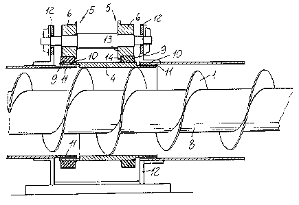
Figure 1 illustrates a side view of the auger, in which the
rotary pipe has been shown partially cross-sectioned: and
Figure 2 is a front cross-sectional view of the auger
according to the present invention.
DESCRIPTION OF THE PREFERRED EMBODIMENT
With reference to the figures of the accompanying drawings.
the fixed channe l and rotary pipe auger according to the invention
comprises a plurality of alternated portions of a rotary spiral 1 within
an outer fixed channel 2 and, respectively, of a fixed spiral 3 which is
clamped within an outer

~a~3~~~
pipe 4 which can turn rigidly with the fixed spiral.
According to a preferred embodiment of the
invention, the rotary pipe portions 4 have a like
length and bear on outer supporting elements 5.
Said supporting elements 5 are substantial-
1y formed by pairs of centering rollers 6, vahich are
connected by shafts 7 parallel to the axis 8 of the
spiral 3.
In a further preferred embodiment, the pairs
of rollers 6 are three in number, and are symmetric-
ally spaced on the circumference of the pipe 4.
At the centering rollers 6, the outer sur-
face of the rotary pipes 4 is provided with guides
or tracks 9 having a circular crown arrangement.
In particular, the tracks 9 are specifical-
1y processed in order to provide good sliding pro-
perties.
The fixed channel portions 2 and rotary
pipes 4, alternatively, can be made as an outer
jacket, at the end superimposed portions thereof,
so as to define a single containing tubular body.
The mutual sealing of said fixed channel
portions 2 and rotary pipes 4 is assured by suitable
gaskets 11 made of any suitable abrasion resisting

20~321~
material.
The outer roller supporting shafts 7 are
supported by a supporting frame 12 which is welded
to the fixed outer channel 2.
The rollers 6 have the rims thereof provid-
ed with an edge portion 14 adapted to abut on the
inner face of the sliding guides 9.
From the above disclosure and the figures
of the accompanying drawings, it should be apparent
that the invention fully achieves the intended aim
and objects.
In particular, there are solved the tech-
nical and economic problems of prior supporting ele-
ments which are at present used inside the channels,
with respect to the conveyance capability of the
auger, the resistance to the movement, reliabili-
ty and maintenance.
Moreover, there are enhanced the conveyance
properties for loose materials such as cereals,
meals, cement powders, as well as wood meals and
pastes.
In fact, owing to the invention, it is pos-
Bible to achieve, since the cost increase of 'the new
supporting elements is counterbalanced by the small-

l0 2U'~3~17
er diameter of the channel, with a consequent small-
er consume of materials, the high longitudinal ex-
tensions necessary in the processing industries,
without increasing the cost for unit of length.
While the invention has been illustrated
and disclosed with reference to preferred embodiments
thereof, it should be apparent that the disclosed
embodiments are susceptible to several modifications
and variations all of which will come within the
spirit and scope of the appended claims.

Dessin représentatif
Une figure unique qui représente un dessin illustrant l'invention.
États administratifs

2024-08-01 : Dans le cadre de la transition vers les Brevets de nouvelle génération (BNG), la base de données sur les brevets canadiens (BDBC) contient désormais un Historique d'événement plus détaillé, qui reproduit le Journal des événements de notre nouvelle solution interne.

Veuillez noter que les événements débutant par « Inactive : » se réfèrent à des événements qui ne sont plus utilisés dans notre nouvelle solution interne.

Pour une meilleure compréhension de l'état de la demande ou brevet qui figure sur cette page, la rubrique Mise en garde , et les descriptions de Brevet , Historique d'événement , Taxes périodiques et Historique des paiements devraient être consultées.

Historique d'événement

Description Date
Le délai pour l'annulation est expiré 2006-07-06
Inactive : CIB de MCD 2006-03-11
Lettre envoyée 2005-07-06
Inactive : Grandeur de l'entité changée 2004-07-26
Accordé par délivrance 2003-06-17
Inactive : Page couverture publiée 2003-06-16
Inactive : Grandeur de l'entité changée 2003-04-01
Préoctroi 2003-03-25
Inactive : Taxe finale reçue 2003-03-25
Un avis d'acceptation est envoyé 2002-11-18
Lettre envoyée 2002-11-18
Inactive : Approuvée aux fins d'acceptation (AFA) 2002-11-04
Modification reçue - modification volontaire 2002-08-02
Inactive : Dem. de l'examinateur par.30(2) Règles 2002-02-07
Modification reçue - modification volontaire 1999-08-31
Inactive : Dem. traitée sur TS dès date d'ent. journal 1999-03-05
Lettre envoyée 1999-03-05
Inactive : Renseign. sur l'état - Complets dès date d'ent. journ. 1999-03-05
Toutes les exigences pour l'examen - jugée conforme 1999-02-17
Exigences pour une requête d'examen - jugée conforme 1999-02-17
Demande publiée (accessible au public) 1993-01-24

Historique d'abandonnement

Il n'y a pas d'historique d'abandonnement

Taxes périodiques

Le dernier paiement a été reçu le 2003-03-19

Avis : Si le paiement en totalité n'a pas été reçu au plus tard à la date indiquée, une taxe supplémentaire peut être imposée, soit une des taxes suivantes :

  • taxe de rétablissement ;
  • taxe pour paiement en souffrance ; ou
  • taxe additionnelle pour le renversement d'une péremption réputée.

Les taxes sur les brevets sont ajustées au 1er janvier de chaque année. Les montants ci-dessus sont les montants actuels s'ils sont reçus au plus tard le 31 décembre de l'année en cours.
Veuillez vous référer à la page web des taxes sur les brevets de l'OPIC pour voir tous les montants actuels des taxes.

Historique des taxes

Type de taxes Anniversaire Échéance Date payée
TM (demande, 5e anniv.) - petite 05 1997-07-07 1997-06-19
TM (demande, 6e anniv.) - petite 06 1998-07-06 1998-07-02
Requête d'examen - petite 1999-02-17
TM (demande, 7e anniv.) - petite 07 1999-07-06 1999-07-05
TM (demande, 8e anniv.) - petite 08 2000-07-06 2000-06-30
TM (demande, 9e anniv.) - petite 09 2001-07-06 2001-07-03
TM (demande, 10e anniv.) - petite 10 2002-07-08 2002-07-08
TM (demande, 11e anniv.) - générale 11 2003-07-07 2003-03-19
Taxe finale - générale 2003-03-25
TM (brevet, 12e anniv.) - petite 2004-07-06 2004-07-06
Titulaires au dossier

Les titulaires actuels et antérieures au dossier sont affichés en ordre alphabétique.

Titulaires actuels au dossier
ROBERTO BERTOLA
DANTE MORONI
Titulaires antérieures au dossier
S.O.
Les propriétaires antérieurs qui ne figurent pas dans la liste des « Propriétaires au dossier » apparaîtront dans d'autres documents au dossier.
Documents

Pour visionner les fichiers sélectionnés, entrer le code reCAPTCHA :


Pour visualiser une image, cliquer sur un lien dans la colonne description du document. Pour télécharger l'image (les images), cliquer l'une ou plusieurs cases à cocher dans la première colonne et ensuite cliquer sur le bouton "Télécharger sélection en format PDF (archive Zip)" ou le bouton "Télécharger sélection (en un fichier PDF fusionné)".

Liste des documents de brevet publiés et non publiés sur la BDBC .

Si vous avez des difficultés à accéder au contenu, veuillez communiquer avec le Centre de services à la clientèle au 1-866-997-1936, ou envoyer un courriel au Centre de service à la clientèle de l'OPIC.


Description du
Document 
Date
(aaaa-mm-jj) 
Nombre de pages   Taille de l'image (Ko) 
Abrégé 1993-11-26 1 10
Revendications 1993-11-26 2 33
Description 1993-11-26 9 172
Dessins 1993-11-26 2 43
Revendications 2002-08-05 2 42
Description 2002-08-05 9 198
Dessin représentatif 2002-11-03 1 17
Dessin représentatif 1999-03-10 1 23
Accusé de réception de la requête d'examen 1999-03-04 1 178
Avis du commissaire - Demande jugée acceptable 2002-11-17 1 163
Avis concernant la taxe de maintien 2005-08-30 1 172
Correspondance 2003-03-24 1 27
Taxes 2004-07-05 1 31
Taxes 1996-07-02 1 59
Taxes 1995-06-21 1 63
Taxes 1994-06-22 1 44