Note: Descriptions are shown in the official language in which they were submitted.
CA 02073225 2002-05-O1
79654-1
Background of the Invention
This invention relates to voice distribution and
switching and, in particular, to combining voice
distribution and switching with video distribution on a
broadband coaxial cable network.
In U.S. patent 5,351,234 dated September 27, 1994
assigned to the same assignee hereof, there is disclosed an
improved system for providing voice and video distribution
over a cable network. In the system of the '234 patent, a
plurality of telephone user or subscriber locations are
provided and each subscriber location has an associated RF
transmitting channel and an associated RF receiving channel.
Theses channels carry voice and signalling information to
and from, respectively, the subscriber locations.
A broadband cable network communicates with the
subscriber locations and carries or couples with the
associated RF transmitting and receiving channels. The
cable network also communicates with a centralized switching
and control means which is adapted to enable the RF
transmitting channels to be selectively coupled or switched
to any of the RF receiving channels. As a result, voice
communication between the associated subscriber locations of
the coupled channels can be carried out.
The particular switching means disclosed in the
'234 patent comprises a time division multiplex (TDM) switch
and a frequency/time conversion means. The latter
conversion means establishes transmitting and receiving TDM
digital channels corresponding to the transmitting and
receiving RF channels so as to permit switching between
channels by the TDM switch. Also, in the system of the '234
patent, the RF transmitting and receiving channels are
-1-
CA 02073225 2002-05-O1
79654-1
analog channels organized into broadband RF channels of the
cable network. Each user location, in turn, is assigned and
couples with the broadband RF channel or channels containing
its associated transmitting and receiving channels.
As can be appreciated, the conventional cable
network used in the system of the '234 patent includes many
active and passive components, such as, for example,
amplifiers, diplex filters, directional couplers, splitters
and combiners. For such a cable network, standards have
been established for its end-to-end characteristics. In
particular, I.E.E.E. standard 802.7 requires that the
network be designed such that it receives broadband RF
signals in a standard RF channel (typically, a 6Mhz channel)
at a level of +54dBmV and outputs these signals at a level
in the range of +5 dBmV to +15 dBmV. This standard further
requires that downstream signals (those in a receive
channel) exhibit a signal-to-noise ratio of at least 43d8,
while upstream signals (those in a transmit channel) exhibit
a signal-to-noise ratio of 4ldB.
When 900 (or 1000) standard voice channels (each,
typically 4Khz wide) are combined in one RF broadband
channel (6Mhz channel) in the '234 patent system, the
maximum signal power applied to each voice channel will be
approximately 30dB less than the total power which can be
applied to the broadband channel. This is based upon an
effective noise bandwidth for the 6Mhz broadband channel of
about 4Mhz, since, as will be discussed, hereinbelow
vestigial sidebands occupy part of this channel.
Accordingly, the power of the noise in each 4Khz voice
channel will also be approximately 30dB less than the noise
carried in the broadband channel. Since both the signal and
noise power each drop by 30dB in each voice channel, the
signal to noise ratio in each channel will remain the same
-2-
CA 02073225 2002-05-O1
79654-1
as that for the broadband channel, i.e., 43dB in the
downstream direction and 4ldB in the upstream direction.
The aforesaid signal to noise ratios, however, are
less than those typically recommended for conventional
telephone communications. According to Transmission Systems
for Communications, 4th edition, Bell Telephone Labs, 1969,
p. 40, a typical telephone system operates with speech at -
41.4dBm, on average, with louder spurts at +lOdBm, or a
ratio of 51.4dB. Furthermore, according to CCITT
recommendation 6.222 for standard telephone systems, noise
in a 4Khz voice channel should be 2500pW at a OdBm point. A
standard 4Khz telephone channel should thus exhibit a
signal-to-noise ratio on the order of about 56dB which, as,
above-noted, is higher than that expected for the 4Khz voice
channels in the system of the '234 patent.
It is therefore, an object of the present
invention to improve the system of the '234 patent.
It is a further object of the present invention to
modify the system of the '234 patent so as to obtain higher
signal-to-noise ratios for the voice channels of the system.
Summary of the Invention
In accordance with the principles of the present
invention, the above and other objectives are realized in
the above-described system of the '234 patent by providing a
further means which is responsive to the centralized
switching and control means of the system and which is able
to enable selective adjustment of the level of the voice and
signalling information in the RF receiving and transmitting
channels of the system.
-3-
CA 02073225 2002-05-O1
79654-1
In the embodiment of the system described
hereinbelow, the adjusting means is able to adjust the power
level of the voice and signalling information in each
channel of the system. This adjustment is able to be
carried out at the cable network/central switch means end,
i.e., the switch end, of the system, and at the subscriber
location/cable network end, i.e., the subscriber end of the
system.
First and second attenuation means, respectively,
are provided for this purpose for each channel and a control
means included in the adjusting means develops signals for
controlling these attenuators based upon the traffic
condition (i.e., active RF voice channels, idle RF voice
channels, etc.) of the switch. The signals developed for
controlling the second attenuation means of the channels
(i.e., those at the switch end of the system) are directly
applied to these means. The signals for the first
attenuation means (i.e., those at the subscriber end of the
system) are incorporated into signalling information sent by
the central switch means to the subscriber locations. This
signalling information, when received at each respective
subscriber location, is sensed by a subscriber location
control means which enables control of the first attenuator
means at the respective location.
In the disclosed embodiment, the adjusting means
determines an adjusted power level signal based on the
aforesaid traffic condition of the switch, the available
power in each RF broadband channel and the power in the
active channels. This adjusted power level signal is then
used to set the first and second attenuation means of the
idle channels. Channels, once they become active, are not
further adjusted during their active state so as to not
disturb voice communication in progress.
-4-
CA 02073225 2002-05-O1
79654-1
In accordance with the present invention, there is
provided a system comprising: a plurality of telephone
subscriber locations, each telephone subscriber location
including means for establishing an RF transmitting channel
and an RF receiving channel associated with the subscriber
location for conveying signalling and voice information from
and to, respectively, the subscriber location; a broadband
cable network for carrying the RF receiving and transmitting
channels of said subscriber locations; central switch means
responsive to said cable network for enabling each RF
transmitting channel on the cable network to be selectively
coupled to any of the RF receiving channels on the cable
network, whereby communication between the subscriber
locations of the coupled channels is enabled; and adjusting
means responsive to said central switching means for
enabling selective adjustment of the level of the signalling
and voice information on each RF transmitting channel and on
each RF receiving channel.
In accordance with the present invention, there is
also provided a method comprising: for each of a plurality
of telephone subscriber locations, establishing an RF
transmitting channel and an RF receiving channel associated
with the subscriber location for conveying signalling and
voice information from and to, respectively, the subscriber
location; carrying the RF receiving and transmitting
channels of said subscriber locations on a broadband cable
network; using a central switch means to enable each RF
transmitting channel on the cable network to be selectively
coupled to any of the RF receiving channels on the cable
network, whereby communication between the subscriber
locations of the coupled channels is enabled; and responsive
to said central switching means, enabling selective
adjustment of the level of the signalling and
_5_
CA 02073225 2002-05-O1
79654-1
voice information on each RF transmitting channel and on
each RF receiving channel.
In accordance with the present invention, there is
further provided apparatus for use with a telephone
subscriber location, the telephone subscriber location being
used with other telephone subscriber locations and with a
broadband cable network for carrying RF transmitting and
receiving channels associated with the subscriber locations,
with a central switch means responsive to the cable network
for enabling each RF transmitting channel on the cable
network to be selectively coupled to any of the RF receiving
channels on the cable network and with adjusting means for
enabling selective adjustment of the level of the signalling
and voice information on each RF transmitting channel and
each RF receiving channel, the apparatus comprising: means
for establishing an RF transmitting channel and an RF
receiving channel associated with said subscriber location
for conveying signalling and voice information from and to,
respectively, the subscriber location; means adapted for use
in coupling said apparatus with said cable network; and
means responsive to the signalling information in said
established RF receiving channel for adjusting the level of
the signalling and voice information in said established RF
transmitting and RF receiving channels.
In accordance with the present invention, there is
further provided apparatus for use with telephone subscriber
locations, each telephone subscriber location including
means for establishing an RF transmitting channel and an RF
receiving channel associated with the subscriber location
for conveying signalling and voice information from and to,
respectively, the subscriber location, and with a broad band
cable network for carrying the RF receiving and transmitting
channels of said subscriber locations, said apparatus
-5a-
CA 02073225 2002-05-O1
79654-1
comprising: central switch means responsive to said cable
network for enabling each RF transmitting channel on the
cable network to be selectively coupled to any of the RF
receiving channels on the cable network; means adapted to
couple said central switch means and said cable network; and
adjusting means responsive to said central switch means for
enabling selective adjustment of the level of the signalling
and voice information on each RF transmitting channel and on
each RF receiving channel.
In accordance with the present invention, there is
further provided a method for use with a telephone
subscriber location, the telephone subscriber location being
used with other telephone subscriber locations and with a
broadband cable network for carrying RF transmitting and
receiving channels associated with the subscriber locations,
with a central switch means responsive to the cable network
for enabling each RF transmitting channel on the cable
network to be selectively coupled to any of the RF receiving
channels on the cable network and with adjusting means for
enabling selective adjustment of the level of the signalling
and voice information on each RF transmitting channel and
each RF receiving channel, the method comprising:
establishing an RF transmitting channel and an RF receiving
channel associated with said subscriber location for
conveying signalling and voice information from and to,
respectively, the subscriber location; coupling said RF
transmitting and receiving channels with said cable network;
and responsive to the signalling information in said
established RF receiving channel, adjusting the level of the
signalling and voice information in said established RF
transmitting and RF receiving channels.
In accordance with the present invention, there is
further provided a method for use with telephone subscriber
-5b-
CA 02073225 2002-05-O1
79654-1
locations, each telephone subscriber location including
means for establishing an RF transmitting channel and an RF
receiving channel associated with the subscriber location
for conveying signalling and voice information from and to,
respectively, the subscriber location, and with a broadband
cable network for carrying the RF receiving and transmitting
channels of said subscriber locations, said method
comprising: using a central switch means responsive to said
cable network, permitting each RF transmitting channel on
the cable network to be selectively coupled to any of the RF
receiving channels on the cable network; coupling said
central switch means and said cable network; and responsive
to said central switch means, enabling selective adjustment
of the level of the signalling and voice information on each
RF transmitting channel and on each RF receiving channel.
In accordance with the present invention, there is
further provided a system comprising: a plurality of first
telephone subscriber locations, each first telephone
subscriber location including means for establishing an RF
transmitting channel and an RF receiving channel associated
with the first subscriber location for conveying signalling
and voice information from and to, respectively, the first
subscriber location; a broadband cable network for carrying
the RF receiving and transmitting channels of said first
subscriber locations; at least one second telephone
subscriber location; and central switch means responsive to
said cable network and to each said second subscriber
location for enabling each RF transmitting channel on the
cable network to be selectively coupled to any of the RF
receiving channels on the cable network and to enable each
second subscriber location to be coupled to each RF
transmitting and receiving channel on the cable network,
whereby communication between the first subscriber locations
-5c-
CA 02073225 2002-05-O1
79654-1
and between the first subscriber locations and each second
subscriber location is able to be enabled.
In accordance with the present invention, there is
further provided a method comprising for each of a plurality
of first telephone subscriber locations, establishing an RF
transmitting channel and an RF receiving channel associated
with the first subscriber location for conveying signalling
and voice information from and to, respectively, the first
subscriber location; carrying the RF receiving and
transmitting channels of said first subscriber location on a
broadband cable network; providing at least one second
subscriber location; using a central switch means to enable
each RF transmitting channel on the cable network to be
selectively coupled to any of the RF receiving channels on
the cable network and to enable each second subscriber
location to be coupled to each RF transmitting and receiving
channel on the cable network, whereby communication between
the first subscriber locations and between the first
subscriber locations and each second subscriber location is
able to be enabled.
Brief Description of the Drawinas
The above and other features and aspects of the
present invention will become more apparent upon reading the
following detailed description in conjunction with the
accompanying drawings in which:
FIGS. 1A and 1B show a video/voice distribution
system as disclosed in the '234 patent;
-5d-
CA 02073225 2002-05-O1
79654-1
FIGS. 2A and 2B each show TDM voice channels used
in the system of FIG. l;
FIG. 3 shows the TDM voice channels of FIGS. 2A
and 2B converted into a corresponding group of RF voice
channels forming an RF voice channel sub-group;
-5e-
2a'~~~~
.. . . .. ,:::. .: :. .......:....:..: :.:.:...:...... . .: . .
j
FIG. 4 shows additional RF voice channel sub-groups
i multiplexed with the voice channel sub-group of FIG. 3 to form a
f; broadband RF voice channel group;
,; FIG. 5 shows the broadband RF voice channel group of FIG. 4
(~ modulated onto an RF cable network carrier with other contiguous !
broadband RF voice channel groups and broadband RF video
channels;
IFIG. 6 shows schematically equipment for realizing the
broadband RF voice channel group of FIG. 4;
jj FIG. 7 shows the details of the modulation/demodu.tation
II aPParatus used at the subscriber locations of the system of FIG. l
1i
(j FIG. 7A shows the demodulation portion of the VSB
modulator/demodulator of the cable network modified to ensure use.
.i
of a network carrier having a stable phase;
FIG. 8 shows a timing chart for operation of the system of
i;
j FIG. l;
FIG. 9 shows the details of the interface unit used at the r
i
i subscriber locations of the system of FIG. 1;
j FIG. 10 illustrates a modification of the i
!j modulation/demodulation apparatus of FIG. 7.
FIG. 11 shows the cable switch end of the system of FIGS. 1A.
it and 1B modified to provide signal level adjustment in accordance
i~ with the principles of the present invention; .
FIG. 12 shows the subscriber end of the system of FIGS. 1A
(~ and 1B and, in particular, the modulation/demodulation apparatus
CA 02073225 2002-05-O1
79654-1
used at this end and shown in FIG. 7, modified to provide
signal level adjustment in accordance with the principles of
the present invention;
FIG. 13 shows the signal adjusting circuits shown
in FIG. 11 in greater detail; and
FIGS. 14 and 15 show flow diagrams for effecting
signal level adjustment in accordance with two different
illustrative level adjustment formulations.
Detailed Description
The description to follow ending on page 30 and
FIGS. 1-10 describe and show a video/voice distribution
system as described and shown in the '234 patent. The
description from page 30 to page 45 and FIGS. 11-15 describe
and show a modification of the '234 patent system in
accordance with the principles of the present invention.
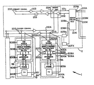
As shown in FIGS. 1A and 1B, the system 1
comprises a broadband coaxial network 2 which carries voice
and video RF channels to voice and video equipment at the
subscriber locations 7A to 7Y. More particularly, the
broadband coaxial network 2 comprises a vestigial sideband
("VSB") demodulator/modulator 206 which transmits RF video
channels and transmits and receives RF voice channels over a
primary coaxial system 200 having feeder coaxial branches
205. The feeder coaxial branches 205 connect to the primary
coaxial branch 200 through bridging amplifiers 204. They
also connect to the televisions 600A-600Y at the subscriber
-7-
locations 7A-7Y via drops 211A-211Y.
As shown, the coaxial branch 200 and each of its feeder '
ibranches 205 comprise an incoming or upstream coaxial cable 201
ii and an outgoing or downstream coaxial cable 202. Line amplifiers
203 are connected to the cables 201 and 202 at preselected - ,
intervals, e.g., intervals of approximately one half mile, to -'
compensate for signal attenuation.
In the present case, the broadband coaxial network 2 is of
the type typically used to distribute video signals and, thus,
r.
i~ has a broad bandwidth reaching as high as about 900Mhz. '
~ Furthermore, to permit concurrent distribution of multiple video
~ signals on the network, the 90oMhz bandwidth of the network is
divided into multiple, contiguous broadband RF channels, each
;( individual broadband RF channel being of sufficient bandwidth to
carry an independent video signal. To accommodate standard videos
~ signals, each broadband RF channel would thus be approximately i
6MHz wide.
~I
The VSB demodulator/modulator 206 receives input video
3~ signals 208A-208X from video or TV sources 207A-207X. Each video,
source 207A-207X might be an antenna or a satellite. The VSB
demodulator/modulator 206 modulates the input video signals onto
a network carrier so that the resultant network signal contains
contiguous or multiplexed broadband RF channels each carrying one.
;of the video signals. This network signal is placed on the
!~ downstream coaxial cable 202 and subsequently received and
:,
~~ decoded by the televisions 600A-600Y located at the subscriber
_ g
2~'~3~~~
~ locations 7A-7Y.
1j The system 1 is further adapted to permit the distribution ,
j~ c~f voice information among the subscriber locations 7A-7Y, as
well as the aforementioned video information. This is
a
j~ accomplished in a manner which allows for a relatively large
number of selectively connectable voice channels and, therefore, ~
~ a relatively large number of subscriber locations capable of ~ ,
voice communication with one another.
More particularly, a number of broadband RF (i.e., 6MHz)
p channels of the cable network 2 are used to carry voice
jj information and associated signalling and control information '
I~ among the subscriber locations. This is accomplished by adapting'
j4 the system 1 for each subscriber location to establish associated'
j RF transmitting and RF receiving voice channels and by allocating
(~ these voice channels to one or more of the broadband RF channels
being used for voice transmission. It is further accomplished byl
ii adapting the system 1 to provide central switching and control of!
ji the RF transmitting and receiving voice channels such that each i
3 ,
~; RF transmitting voice channel can be selectively switched or
I~ coupled to any one of the RF receiving voice channels. In this
jj way, a voice path can be established between each subscriber I
~3 location and any of the other subscriber locations in the system. '
In the present illustrative embodiment, the RF transmitting
~j and receiving voice channels of each subscriber location are
,i established by a respective drop box (i.e., 5A, 5B..., 5Y located'
;~ at the particular subscriber location. The RF voice channels
_ g _
.. . . . . .~ _~ .o~..~i~,J: uv . h. : ,.o.",
~I associated with the different subscriber locations are, i
;i furthermore, established by the respective drop boxes so that
i
they form RF voice channel groups, each voice channel group being!
allocated to a different one of the RF broadband channels
assigned to voice transmission and being carried by the network 21
;; carrier. ' -
In the present case, since the network 2 includes an
upstream cable 201 as well as a downstream cable 202, the RF I
tra»smitting voice channel and RF receiving voice channel of each
i, subscriber location can occupy the same RF band. Also, because
the RF receiving and RF transmitting voice channels of a given !
,, subscriber location can occupy the same RF band, they can also be~
carried in the same RF broadband channel of the cable network.
;, In the event the cable network 2 were modified to use only a'
single cable for upstream and downstream transmission, the RF
transmitting and RF receiving voice channels would have to be
.r offset from each other to prevent interference. In such
;; situation, the channels would likely be required to occupy 3
p separate RF broadband channels of the cable network.
. '.
;j As above-indicated, the RF transmitting voice channel groupsl
!; established by the subscriber locations are carried in the
upstream cable 201 in the multiplexed broadband RF channels of .
;; the network 2. Similarly, the RF receiving voice channel groups i
;, are carried via the downstream cable 202 again in the multiplexed
RF broadband channels of the network.
As also above indicated, the system 1 is adapted to provide
- IO -
1
centralized, selective switching or coupling of the voice
information and associated signalling information in each RF
transmitting channel to any one of the RF receiving channels. In
ii the present illustrative example, this is effected by a digital
switch 3, which is shown as including a TDM switch 302 and a CPU
309, and by a time/frequency converter assembly 4. The converter'
assembly 4 includes individual time/frequency converter units 4A .
I) to 4M, each assigned to a particular RF broadband channel
carrying a frequency division multiplexed (FDM) RF voice channel i
j group .
More particularly, after demodulation of the upstream
network signal to produce the individual RF broadband channels,
;! the modulator/demodulator 206 passes the broadband channels to
f~ respective output ports 210A to 210M connected to converter units:
f~ 4A-4M, respectively. Each converter unit then converts the RF
~~ transmitting voice channels in its received RF broadband channel j
f~ into corresponding digital voice channels and one or more control
(~ channels organized into one or more TDM signals for processing by
~~ the digital switch 3. .
jj As a result of its processing, the digital switch 3 places
1! voice and signalling information into digital voice channels and
~f one or more control channels which'correspond to the receiving RF
;j voice channels. The switch 3 organizes these digital voice
,' channels and control channels also into one or more TDM signals
and conveys these signals to their associated converters 4A to
4M, i.e., to the respective converters assigned to the RF
- 11 -
j
II broadband channel carrying the corresponding RF voice channels.
i
Each converter then converts its received digital channels into a;
;i carresponding FDM RF receiving voice channel group. Each '
receiving voice channel group is then delivered to the '
j1 modulator/demodulator 206 where it is placed in the corresponding)
(j broadband RF channel and modulated onto the network.:carrier for I
subsequent delivery to the subscriber locations via the
fl downstream cable 202. I
() In the present illustrative case of the use of TDM switch i
' i
ji 302 in the digital switch 3, the digital voice channels
(~ transmitted between the switch and each of the converters 4A to '
4M are contained in time slots of the generated TDM signals.
Each time division multiplexed signal contains a number of
n
jj digital voice channels, a synchronization channel and a control I
channel for control and signalling information.
The TDM signals are communicated to and from the TDM switch I
~i 302 by digital trunk units (DTUs) included in the switch 3. A
,:
I, group of these units is associated with each converter unit 4A toj
4M (e. g., DTU~s 301A to 301N and 302A to 302N are associated withi
~~ converter 4A). Each converter unit 4A to 4M, in turn, comprises
~~ a number of time/frequency converters (e.g., TRANSMUXES 401A to
I,
401N) each of which transmits and receives the TDM signals from ai
!!
~~ pair of DTUs (e.g., DTUs 301A and 302A are paired with TRANSMUX
.j 401A)
Each of the TRANSMUXES in the units 4A to 4M converts its j
j! received digital voice channels and its received synchroniztion
' - 12 -
..
.' and control channels into a corresponding FDM sub y~....~. ..
receiving voice channels. Each FDM channel sub-group is then t
combined by a demultiplexer/multiplexer (DEMUX/MUX) unit in the
respective converter (e.g., DEMUX/MUX 400A in converter 4A) with I
i
,. other channel sub-groups to generate an FDM RF channel group
.~ which is delivered to a respective receive port 209A to 209M on
n the modulator/demodulator 206. w-
In the other direction, the reverse process occurs in each
~~ of the converter units 4A to 4M. Thus, the FDM RF transmitting
voice channel group received at each converter 4A to 4M is !
separated by the DEMUX/MUX into FDM sub-groups of RF transmit
voice channels. These FDM sub-groups are then fed to respective
TRANSMUXES, where they are converted to TDM time signals having
corresponding digital transmit voice channels and associated
p synchronization and control channels. These TDM signals are
~j delivered to corresponding DTUs and processing by the TDM switch i
~~ 302.
;; FIGS. 2A and 2B show the format of the TDM signals I
;~ transmitted between the DTUs 301A and 302A and the TRANSMUX 401A
y of the converter unit 4A. Each signal is shown as carrying 30
~'~ digital voice channels (T1-T15 and T17-T32), one synchronization
'; channel (TO) and one control channel (T16), the two signals
i; together accounting for 60 voice channels.
FIG. 3 illustrates the FDM RF receiving voice channel
sub-group signal transmitted between the TRANSMUX 401A and
~~ DEMUX/MUX 400A of the unit 4A. This signal results from
- 13 -
~~~3~~.~ ..
frequency conversion of the TDM signals of FIGS. 2A and 2B. As
!j shown, each digital voice channel is converted into a 4KHz wide
RF voice channel, resulting in 60 RF voice channels, each
;, containing the voice, control and synchronization information
~) Pertaining to its associated digital channels.
FIG. 4 illustrates the resultant FDM RF receiving voice
channel group signal delivered by the DEMUX/MUX 400 as a result
of the applied FDM RF sub-groups from the TRANSMUXES 401A to
II 401N. The illustration assumes 15 TRANSMUXES in the converter
,i
4A, resulting in (15x60) or 900 RF receive voice channels over a
i.
jj frequency band of 312 KHz to 4028 KHz.
j! Finally, FIG. 5 shows the downstream network signal from the'
j1 modulator/demodulator 206. As shown, the FDM RF receiving voice
I~ channel group of FIG. 4 has been modulated onto the network
!I carrier (361.25 Mhz) in a first 6MHz RF broadband channel. Also
ji shown is another FDM RF receiving voice channel group containing
~~ RF voice channels 901 to 1800 modulated onto the network carrier .
1j in a second 6MHz channel contiguous with the first channel. As j
~~ mentioned earlier, the downstream signal also contains video
ji channels, (VIDEO A and VIDEO B), also modulated onto the carrier
j= in further multiplexed 6MHz broadband channels.
I; As above-indicated, the RF transmitting and receiving. voice
channels are coupled to and from their corresponding subscriber
locations via respective dropboxes 5A to 5Y. Referring to
;j dropbox 5A for illustrative purposes, the dropbox comprises a VSB .
! modulator/demodulator or modem 502A, a single channel multiplexes '
- 14 -
i
il
;; '
i, 501A, and an interface unit 500A. The VSB modem 502A has a
receiving port 504A which connects to the downstream cable 202 at!
drop 211A and a transmitting port 503A which connects to the
upstream cable 201 at drop 212A.
The VSB modem 502A is configured to demodulate or extract
ii from the downstream network signal the broadband RF channel ' ,
p (i.e., 6MHz channel) containing the RF receiving voice channel
Ii associated with the subscriber location 7A. Thus, assuming the
subscriber location 7A corresponds to the RF receiving voice
ii channel 1 in the network signal of FIG. 5A, the modem 502A will
i1 extract from this signal the first broadband RF channel (i.e, the
360-366 MHz channel), since it contains the RF receiving voice
'. channel 1. Conversely, an RF transmitting voice channel 1 sent
by the single channel multiplexes 501A to the VSB modem 502A will
!~ be modulated by the VSB modem 502A into the first broadband RF
~i channel and then transmitted from port 503A of the modem to the t
j1 upstream cable 201.
The first broadband RF voice channel (366-366MHz) once .
~~ extracted by the modem 502A, is then conveyed to the single
II channel multiplexes 501A which is configured to demodulate the RF
_~ channel group to obtain the associated RF receiving voice channel
ii (channel 1) and return this channel to base band to recover the
'; resultant 4KHz baseband receiving channel. This channel is then i
;. processed to extract voice information (i.e., band limited to
;,300-3400Hz) and also processed to extract any out-of-band
;v signalling information. The voice information is then passed via '
- 15 -
il
~i
..
ij output port 507A to an input port 505A of an interface unit 500A.t
., The signalling information is, in turn, passed via another output.
port Mm to a further input port Ei of the interface unit. ;
In the transmit direction, the single channel multiplexes
j, 501A receives at its input port 508A from the output port 506A of
;i the interface unit 500A, baseband voice information. The
;j multiplexes also receives signalling information~at its Em port
!; from the Mi port of the interface unit. This voice and
j; signalling information is, in turn, modulated by the multiplexes
.. into the RF transmitting voice channel (i.e., channel 1) and sent'
by the multiplexes to the modem 502A where it is placed in the
first RF broadband channel of the network 2, as above-described.
The interface unit 500A provides a standard tip T and ring R
connection to a phone 601A located at subscriber location 7A.
!~ The band-limited receiving voice channel information at the input)
j~ terminal 505A of the interface unit 500A is provided to these
;; connections so that voice information becomes available at the
~1 phone 60)A. Further, transmitted voice information received from.
if the phone 601A on the tip T and ring R connections is transferred'
jj by the output terminal 506A of the interface unit 500A to the
single channel multiplexes for inclusion in the transmitting .
'j voice channel being transmitted at the subscriber location.
The interface unit 500A also develops signalling information
based upon the signalling information received at its Ei port and
,j the state of the~phone 60)A. This signalling information is
passed from the Mi port of the interface to the Em port of the
- 16 -
me>dem where it is included in the RF transmitting voice channel '
developed by the modem, as above-described.
j. It is desirable to avoid frequency shifts in the modulating '
;! and demodulating process performed at the drop boxes 5A to 5Y. .
To achieve synchronization, the system 1 is further adapted to
,..
provide a synchronizing pilot signal at the drop boxes. This
signal is supplied from the reference source used to generate the'
Ij RF channel group signals at the DEMUX/MUX 400A.
FIG. 6 shows in greater detail the multiplexing section of
.; the DEMUX/MUX 400A used to generate the RF channel group of FIG.
5. A 4Khz reference frequency source 700 serves as the primary
source for generating both pilot signal and reference frequencies'
for multiplexing the RF channel sub-groups (i.e., groups 2-16).
j~ More particularly, the reference frequency is applied to a pilot .
frequency multiplier 701 which multiplies the frequency by 77 to
~i develop a 308 KHz pilot signal. This signal is modulated onto
~~ the network carrier provided by a carrier source 704 to the VSB
i~ modulator/demodulator 206. The pilot signal is then recovered at~
'~ the drop boxes and used to develop reference frequencies for
i~ demodulation and modulation as described below. '
As is also shown in FIG. 6, the 4Khz reference frequency is
!i also applied to suitable multipliers 702B-702N whose outputs are
;i applied as reference frequencies to the single sideband '
modulators 703B-703N. The latter, in turn, modulate the RF
frequency sub-groups to develop the RF channel group in FIG. 4.
.. This channel group is also applied to modulator/demodulator 206
- 17 -
.. . . .. 2~~3~~~ ,
~. ~
;i
to generate the first broadband RF channel of the signal in FIG. t
i; 5.
!' FIG. 7 shows in greater detail the VSB modem 502A and the
I! single channel multiplexer 501A shown in FIG. 1 modified to
~ utilize the pilot signal generated at the DEMUX/MUX for I
1i synchronization. The network signal received at the VSB modem
input port 504A is supplied to a carrier bandpass filter 802 and,!
I! after passage to VSB demodulator 800, to a pilot bandpass filter
~ 803. The network carrier bandpass filter 802 recovers the I
I~ 361.25Mhz network carrier, while the pilot bandpass filter 803 .
j1 recovers the 308Khz pilot signal. The recovered signals are thent
'j used in the modulator and demodulator processing to ensure
Ii synchronization.
II More particularly, the recovered network carrier is applied .
II to the VSB modulator 807 of the VSB MODEM 502, thereby ensuring (
I~ that modulation occurs at the appropriate frequency. The 308 KHz
i) pilot signal, in turn, is applied to a divide by 77 frequency
i~ divider 804 to recover the 4 Khz reference signal. This signal 1
;I
~' is then applied to a preset multiplier 805 to derive the I
r; reference frequency for the associated RF transmit and receive
~i voice channels of the subscriber location (i.e., the frequency
;~ 312 Khz for the channel 1 of the location 7A). This reference
?frequency is then applied to the SSB Modulator 806 and the SSB
:; Demodulator 801A of the multiplexer to provide the RF transmit
I~ voice channel and recover the baseband voice channel,
respectively.
- 18 -
.1
i
The multiplexes 501A of FIG. 7 also contains bandpass
filters 808 and 810 which are used to band-limit the recovered
baseband voice channel and the voice channel being transmitted,
respectively. Also, the multiplexes is provided with an
out-of-band tone generator 809 and an out-of-band tone detector
811. These components generate and detect a 3825 Hz tone which
~. is used as signalling information in the RF transmit and receive
!i voice channels of the subscriber locations. '
i1 More particularly, 3825Hz signalling tones are used to
~~ provide an indication of on and off hook conditions and to
' generate ringing signals. In the present case, each interface '
unit provides simple logic changes to indicate the on and off
~; hook conditions of its respective phone. These conditions are '
i. used to instruct tone generation by the respective multiplexes.
~i Also, the switch 3 uses 3825 Hz tones to request connection to a
~! subscriber location. These interactions will become apparent in
,~ the description of the operation of the system 1 sat forth '
. hereinbelow.
i) In the system of FIG. 1, the modems 502A-502Y used at the
!1 drop boxes 5A-5Y develop the RF transmitting channels as (
j; vestigial sideband signals. The resultant upstream signal on they
line 201 thus comprises a number of vestigial sideband signals
;: each carrying a part of the network carrier. These signals are
received at the VSB modulator/demodulator 206 which, in
;. accordance with conventional vestigial sideband principles,
~: demodulates the signals by regenerating the network carrier from !
- 19 -
.... ...... ...... ..... ~~.,~~~~~ ..;
I~ the received signals and using the regenerated carrier to
i~ demodulate the signals. This extracts the RF broadband channels .
containing the RF transmitting voice channel groups. Each
;L broadband channel is then applied to the appropriate DEMUXjMUX.
;~ Because the vestigial sideband signals in the upstream
;I signal originate at different subscriber locations they will
;j likely arrive at the modulator/demodulator 206 with different
Ij phases which may vary over time. As a result, the phase of the
j~ network carrier recovered by the VSB modulator/demodulator 206
ii from these signals may also vary with time.
~; If this varying phase of the recovered network carrier is
;; found to be undesirable, the modulator/demodulator 206 can be
y suitably modified to utilize a network carrier for demodulation
~~ whose phase does not vary. .
FIG. 7A shows the demodulation portion of the 1
;,
~~ modulator/demodulator 206 modified to realize this. As can be
'i
(~ seen, the upstream signal into the demodulator is first passed
~ through a band rejection filter 711 which is adapted to reject .
(~ signals at the network carrier frequency (i.e., 361.25 I~iz in the!
I~ present example). The filtered signal is then passed into a VSB ,
(~ demodulator 712 which is now supplied with the network carrier
;; from the carrier source 704 used to supply the VSB modulator 206A
~~ (see, FIG. 6). The demodulated signal is then applied to the
demultiplexer section of the appropriate DEMUX/MUX to recover the
RF channel sub-groups.
In FIG. 7A, the portion of the DEMUX/MUX 400A for recovering'
- 20 -
2~~~~~~ ....
.;
.;
the channel sub-groups 2-16 shown in FIG. 6 is also illustrated. t
,'
i; As shown, SSB demodulators 7058-705N supplied with appropriate
. demodulation frequencies recover the respective channel groups
2-16.
FIG. 8 shows the sequence of events when placing a call from!
the phone 6U1B at the location ?B to the phone 601A at the i
location 7A. In the description, it will be assumed that the-
I~ location 7A uses transmitting and receiving RF voice channel 1
and that the location 7B uses the transmitting and receiving RF 1
voice channel 2, shown in FIGS. 3-5.
j) Step 1: --PHONE 601B OFF-HOOK--; When phone 6018 goes i
~I off-hook, the interface 5008 detects a change in the state of the
associated tip T and ring R lines. ,
Step 2: --3825Hz ON--; The interface 500B transfers a
' logic signal from its Mi port to the Em port of the single
channel multiplexer 501B instructing it to turn on the 3825Hz
tone generator. This causes a 3825 Hz tone to be continuously j
~ .
transmitted in the associated RF transmitting voice channel 2 of j
the network signal of the modem 502B. I
Step 3: --PHONE 601B OFF-HOOK--; The RF txansmitting vaice;
j' channel 2 containing the 3825Hz tone is passed by the
. p modulator/demodulator 206 and DEMUX/MUX 400A to the TRANSMUX 401A;
~ assigned to transmitting channel 2. The TRANSMUX detects the
presence of the 3825Hz tone and transmits an off hook signal to
the TDM switch 302 via DTU 301A. This signal is carried in the
control channel of the TDM signal carrying the transmit voice
- 2I -
~ ~ . . . . ... .... ,....
!! channel 2 and indicates to the switch that the channel 2 is
off-hook.
i
Step 4: --SEND DIALTONE to PHONE 601B--; The TDM switch
302 planes a dial tone signal in the control channel of the TDM
,~ signal carrying the receiving voice channel 2 and it is delivered]
ii by the DTU 301A to the TRANSMUX 401A. The latter places a dial j
!' tone in the RF receiving voice channel 2 which passes via..the
.: downstream network signal to the corresponding drop box 5B. Thisi
j! tone is extracted by bandpass filter 810 in the multiplexes 5018 I
. and passed through the interface circuit 500B to the T and R .
:: lines of phone 601B.
In the remaining discussion of the operating steps of the
w system 1, it will be understood that transmission between the
,~ drop boxes 5A and 5B and the TDM switch 3 occurs over the
~~ associated drop box components, the associated cables, the
!! modulator/demodulator 206, and the associated DEMUX/MUX, TRANSMUX
and DTU, although these components may not be specifically . !
;~ mentioned in the interests of brevity.
j! Step 5: --SEND DTMF PHONE NUMBER--; Upon receiving dial
;, tone, the DTMF phone number of phone 601A is transmitted from !
uphone 601B to the TDM switch 302 over the RF and corresponding
v digital voice channel 2. The digital switch looks up in memory ,
;the DTMF phone number dialed and determines that the phone being !
called is on voice channel l, i.e., is the phone 601A. i
Step 6: °-RING INSTRUCTION--; The TDM switch 302 sends a
message in the control channel of the TDM signal containing the
- 22 -
i
a
voice channel 1 instructing the TRANSMUX 401A to turn on a 3825Hz~
;;
tone in RF receive voice channel 1.
Step 7: --SEND RING TONE TO ORIGINATOR--; The TDM switch
,i 302 then sends a ringing tone to phone 601B via voice channel 2.
Step 8: --3825Hz ON--. The TRANSMUX 401A turns on the
3825Hz signal for the receiving voice channel 1.
jj Step 9: --RING SIGNAL--. The single channel multiplexes
p 501A associated with receiving voice channel 1 and phone 601
Ij detects the presence of the 3825Hz signal and passes a logic
~i signal from its Mm port to the Ei port of interface 500A. The
.. interface 500A then generates a ring signal on the tip T and ring
~' R lines of phone 501A.
Step 10: --PHONE A OFF-HOOK--; When phone 501A is answered
~~ there is a detectable change in the state of the associated tip T
~j and ring R lines.
i~ Step 11: --3825Hz ON--; The interface 500A detects the
!i change in state via a signal to its Em port from the Mi port of
ii the interface. It then instructs the single channel multiplexes
i
(j 501A to turn on its tone generator to initiate a continuous
ii 3825Hz tone in transmitting RF voice channel 1 and ceases
1generating the ringing signal on the tip R and ring R lines of
:i phone 601A.
!I Step 12 --PHONE A OFF-HOOK--; The TRANSMUX associated with
;' transmitting RF voice channel 1 detects the presence of the
3825Hz tone in the RF voice channel 1 and transmits an off-hook
i! signal to the TAM switch 302 via the control channel of the TDM
- 23 -
;; signal containing the transmitting voice channel 1.
Step 13 --STOP RING TONE--; The TDM switch stops the
ringing tone being sent over the RF receiving voice channel 2. ,
Step 14: --VOICE CONVERSATION--; The TDM switch at this
j; time has now established a virtual talk path between the calling ;
i~ phone 6018 and the called phone 601A over the RF transmit and t
!j receive voice Channels 2 and the RF transmit and receive voice t
~ channels 1. Bidirectional conversation can now occur. i
~j Step 15: --PHONE,601B ON-HOOK--; When phone 6018 goes
~j on-hook (i.e., hangs up), the interface 5008 detects a change in
j! the state of the associated tip T and ring R line.
Step 16: --3825Hz OFF--; The interface 5008 via ita Mi port.
;. instructs the single channel multiplexes 5018 via its Em port to
~i turn off the 3825Hz tone generator. .
Step 17: --PHONE 6018 ON-HOOK--; The TRANSMUX 901A assigned
r
~~ to RF voice channel 2 detects the absence of the 3825Hz tone and
!I transmits an on hook signal to the TDM switch 302 in the control '
jj channel of the TDM signal containing the transmit voice channel
.,
i1 2. j
j~ Step 18: --SEND DISCONNECT TONE--; The TDM switch 302 then !,
~~ terminates the virtual path established between voice channel 2
ij and the voice channel 1, i.e., phones 6018 and 601A. The TDM
~; switch then transmits a message over the TDM signal containing
the receiving voice channel 1 to the TRANSMUX instructing the
i
j; TRANSMUX to turn off the 3825 tons in the voice channel 1.
!' Step 19: ~-DISCONNECTED--; The interface 500A detects the
..
- 24 -
.I
absence of a 3825 Hz tone in receiving voice channel 1 and sends
dial tone to phone 601A. I
Step 20: --PHONE ON-HOOK-- When phone 601A is placed
on-hook there is a detectable change on its associated tip T and
.. ring R lines. .
Step 21: --3825Hz OFF--; The interface 500A detects the
if change in state and instructs via its Mi port the single channel
multiplexer 501A at its Em port to cease transmitting the 3825Hz I
!tone in RF voice channel 1.
Step 22 --PHONE 601A ON-HOOK--; The TRANSMUX associated
with RF voice channel 1 detects the absence of the 3825Hz tone in'
voice channel 1 and transmits an on-hook signal to the TDM switch)
302.
The above described process is repeated for subsequent phone;
jj conversations. I
.,
i~ FIG. 9 shows in greater detail an example of the interface !
unit 500A. Similar units can be used for the other interface
:j units 5008-500Y. As shown, a hybrid circuit 900, having a
i
balancing impedance Z, depicted at 905, connects to the TIP and
i
~i RING lines. A receive line 906 and a transmit line 907 from the
.! input terminal 505A and the output terminal 506A, respectively,
connect to the hybrid circuit 900. A scanner 902 is also
connected to the hybrid 900 and detects whether the tip T and
ring R lines indicate an on-hook or off-hook condition. A '
. ringing generator 904 connects to the TIP and RING lines and
. generates a ringing signal when directed to do so by control unit'
25 -
~~'~3~2
j
903.
j1 A control unit 903 receives signals from the scanner 902 and
.i
the Ei input terminal. Further the control unit supplies control
., signals to the ringing generator 904 and the Mi output terminal.
The various states of ports Ei, Mi, the scanner 902 and the ring .
,.
generator 904 as controlled by the control unit 903 are given
tj below. These states follow--from the above discussion of the
i; operation of the system 1. States 2-3 relate to a calling phone
and states 4-6 relate to a called phone. An off-hook status
;: indicates an active state and an on-hook status an inactive
state.
'; State 1: When a phone is idle
Scanner = on hook
Ei = on hook
.l Mi = on hook
.,
Ring Gen. = no ring
.. Switch 302= not connected
State 2: Initiating a pall
p Scanner = off hook
Ei = on hook
i: Mi = off hook
Ring Gen. = no ring
Switch 302= dial tone, busy tone, ringing tone
- 26 -
~~'~32~~
. ...
.,
..
0
State 3: Connection with destination
ii Scanner - off hoak
Ei - off hook
Mi = off hook -
Ij Ring Gen. = no ring
.y
Switch 302= connected 1
:; .
State 4: incoming call
Scanner = on hook
'1 Ei = off hook 1
~! Mi - on hook
Ring Gen. = ring
!! Switch 302m not connected
~ State 5: phone answered
Scanner = off hook '
:I Ei = off hook
11 Mi = off hook '
i~ Ring Gen. = no ring
.1 Switch 302= connected
..
i'
~~ State 6: Calling phone disconnects
:i Scanner - off hook
Ei - on hook
' Mi = off hook
! Ring Gen. ~ no ring
- 27 -
~~'~3~~
Switch 302= not connected
FIG. 10 illustrates a modification of the VSB modem and
single channel multiplexer shown in FIG. 7. In the case of FIG. !
10, the RF transmitting and receiving channels are developed by
direct modulation and demodulation, respectively. This is
realized, in the case of the RF transmitting channel, by
i; modulating the voice and signalling information directly at the
frequency desired for the transmitting channel in the associated ~
i1 RF broadband channel. In the case of the RF receiving channel,
j! it is realized by demodulating the received signal directly at
the frequency of the RF receiving channel in its associated RF
broadband channel. Furthermore, the pilot signal is recovered
from the received signal in the FIG. 10 arrangement by using a
VSB demodulator whose frequency band of operation need only be
sufficiently wide to reach the pilot frequency as modulated onto
the network carrier. ,
In FIG. 10, those components which are the same as those in
FIG. 7 have been numbered the same. As shown, the downstream
signal received at port 504A is applied to direct demodulator j
1002 which directly recovers the RF receiving channel by ,
i; demodulation at the specific carrier frequency of the channel in ,
E! the downstream signal. For example, in the case of the RF
receiving channel 1 in FIG. 5, the demodulation frequency applied!
to demodulator 1001 to recover the channel would be at 361.562
~Wiz. The latter frequency. is generated by a mixer 1002 which
multiplies the recovered network carrier signal (361.25 MHz) by
- 28 -
2~~~~~~
the output signal (for channel 1 this output is at 312KHz) of the:
!j present multiplier 805.
i~ As in FIG. 7, the preset multiplier 805 develops its output
'signal by multiplying the 4KHz reference signal by the factor N.
The 4KHz reference is obtained at the output of the divide by 77
circuit 804 which divides the 308 KHz synchronization pilot
~i signal developed at the output of pilot bandpass filter 803.
II The 308 KHz synchronization signal is generated, in this .
case, from the downstream signal by first passing it through a
l narrow bandpass VSB demodulator 1003. The pass band of this
;; demodulator need only be sufficient to extend to the 308KHz
synchronization signal as modulated on the network carrier (i.e.,
s1 extend to 361.588MHz). The output of the demodulator is then fed
s! to bandpass filter 803 to recover the actual 308KHz signal.
;1
The output of mixer 1002 is also applied to direct modulators
1004. This results in the input voice and signalling signals to
!~ the modulator being directly modulated at frequency (in the case .
of channel 1 at 361.562 MHz) which places the RF transmitting
channel at the desired frequency position in the upstream signal.l
It should noted that the TDM switch 302, the TDUs,
j! TRANSMUXES and the DEMUX/MUX of the digital switch 3 and
~i converter 4 can be provided by suitably modified conventionally
'!, available components operating on a usual CCITT standard used for.
TDM transmission: A particular example of a TDM switch 3 might
'; b~ a Harris ,~20-20 digital switch equipped with a Harris
!s ~ 2M8 DTU operating at CCITT recommendation 6.700. An example of
- 29
a suitable TRANSMUX might be the DSC-Granger TM 7800-M1 TRANSMUX.
A suitable DEMLJX/MUX would be one operating in accordance with I
CCITT recommendation 6.233.
As can be appreciated, with the system 1, it is now possible!
to provide voice communication, via the cable network 2 and the !
' centralized switch 3, between a large number of subscriber
's locations. For the present illustrative case, 900 voice channels
corresponding to 900 subscriber locations have been provided in f
jl each 6MHz RF broadband channel of the cable network, as compared
. to only 28 channels and locations for the prior art systems. '
Moreover, the 900 channels in each 6MIiz broadband channel can be I
connected to each other and any of the channels in the other 6MHz:
channels. Accordingly, by suitable selection of the number of
i broadband channels of the network 2 allocated to voice .
transmission, 10,000 or more selectively interconnectable voice
channels can be provided.
It should be noted that the TDM switch 302 can itself be a
;i switch in a conventional telephone system which is adapted to
ii couple with the cable network as above-described. In such case, I
i subscriber locations (e. g., location 7X) connected to the switch,i
;. but not served by the cable network, can also be connected '
. through the switch and the cable network to the subscriber
'. locations served by the network. Additionally, subscriber '
locations connected through other switches and trunks to the TDM
switch can be similarly connected to the subscriber locations on
the cable network.
- 30 -
'i I
i
i; It should also be noted that the system 1 can be further
modified so that dial tone need not be established at a
subscriber location by the respective interface 500A detecting
the absence of the 3825 Hz tone (step 19 of FIG. 8). Instead,
f when the TDM switch 302 terminates a virtual voice path between
subscriber locations (step 18 in FIG. 8), it can itself directly
.. send dial tone to the subscriber location which is still off-
hook, allowing the off-hook subscriber to establish another call
jj or go on-hook, as desired.
As can be appreciated from the above, the system 1 of FIGS. f
1-10 permits acceptable voice communication over the cable i
network 2. However, as also discussed above, the system 1 may
' not be able to achieve signal-to-noise ratios for the RF transmits
'; and receive voice channels which approach those of standard
telephone systems.
:I FIGS. 11-15 and the discussion that follows show and j
.; describe a modified form of the system of FIGS. 1-10 designed to i
'; provide increased signal to noise ratios for the RF voice
jl channels of the system. In accordance with the principles of thej
present invention, this is accomplished by adding to the system 1i
,i an adjusting means which is responsive to the traffic condition
of the RF transmit and receive channels of the TDM switch 302 and;
;t which adjusts the level and, in particular, the power level, of ,
the voice and signalling information in selective RF transmit and.
receive channels of the system:
n In accordance with this modified form of the invention, it
- 31 -
'~~-'~~~~~
i I
. I
is~assumed that the tone signalling for indicating the on-hook
~I and off-hook conditions of each subscriber location is the !.
inverse of that described for the system of FIGS. 1-10. In
~i particular, an on-hook condition is established by continuously
j~ transmitting a 3825 Hz tone in the transmit channel of a
Ii subscriber location and the off-hook condition is established by
j~ the absence of such tone in the transmit channel. The
!j modifications to the system 1 required to achieve this inverse
:i
~~ tone operation are straightforward and evident to the skilled !
)j artisan and, hence have not been further discussed in detail
herein.
j' Turning to the modified system as shown in FIG. 11, a .
jj traffic sensitive control circuit (TSCC) 1201 is provided at the
jj switch end of the system 1. The TSCC 1201 communicates with the
' CPU 309 of the TDM switch 302 and periodically receives
(~ information relating to the current traffic and, in particular, i
the current traffic of the RF transmit and receive voice channels
I
~~ on the switch. Based upon the current traffic of these RF voice
!i
channels and other relevant information to be discussed
i! hereinbelow, the TSCC 1201 develops signals for enabling control i
ji of the power levels in selective RF transmit and receive channels
of the system.
;! To this end, the TSCC 1201 communicates with channel power !
adjust circuits, shown as circuits 1200A-1200N for the
~j time/frequency converter assembly 4A, which are provided to
:~
ij control the power level in respective transmit and receive RF
- 32 -
2o~~2z~
..
p
~i voice channels at the switch end of the system. Further, the t
TSCC 1201 communicates, via signalling through the CPU 309 and ;
the TDM switch 302, with further power adjust circuits (see,
transmit and receive attenuators in.FIG. 12) for controlling the
.. power levels of the RF transmit and receive voice channels at thei
subscriber end of the system. .
The power adjust circuits at the subscriber end of the
!
system 1 have been incorporated into certain components of the
drop boxes serving the subscriber locations. FIG. 12 shows the 1
components of the drop box 5A serving the subscriber location 7A .
and, in particular, the VSB modem 502A and the single channel
multiplexes 501A depicted in FIG. ?, modified in this manner. !
The other drop boxes of the system are similarly modified.
As shown, a power adjust circuit in the form of a receive
attenuator 1100 is interposed between the VSB demodulator 800 and
~! the SSB demodulator 801 of the single channel multiplexes 501A. ;
The receive attenuator 1100 is responsive to control signals from.
!! a level sensitive control circuit 1101. These signals control
s
~i the magnitude of the attenuation of the attenuator and,
;. therefore, enable adjustment of the power level in the RF receive
voice channel. i
A transmit attenuator 1102 is further interposed between the
. SSB modulator 806 of the multiplexes 501A and the VSB modulator '
807. The return transmit attenuator 1102 is also responsive to ,
control signals from the level sensitive control circuit 1101.
In this case, the signals likewise control the attenuation of the.
- 33 -
iattenuator, thereby enabling adjustment of the power level in the
;; transmit voice channel.
The level sensitive control circuit 1101 is responsive to '
,. the output signal of the 3825Hz tone detector 811. As described ,
previously, the 3825Hz tones are used to convey various j
signalling information in the transmit and receive transmit and '
receive voice channels. In accordance with the present
y modification, these tones axe also used to convey power adjust j
information to the control circuit 1101 for controlling the i
receive and transmit attenuators 1100 and 1102.
More particularly, in the present illustrative case, the
TSCC 1201 first adjusts at the switch end the power levels of the;
particular transmit and receive channels serving an idle
subscriber location, whenever there is a change in status (i.e., ~'
i
idle to active or active to idle) of any RF voice channel of '
if another subscriber location served by the same RF broadband
channel (i.e., 6MHz cable channel). This is explained in greateri
;; detail hereinbelow and is accomplished by the TSCC 1201 causing
i4 adjustment of the appropriate channel power adjust circuit or
i, circuits (e.g., the power adjust circuits 1200A to 1200N in
j, assembly 4A) . i
The level sensitive control circuit 1101 at each idle
ji subscriber location whose RF receive channel has been so adjusted;
at the switch end then receives the 3825Hz tone normallly being
sent to indicate the idle status or on-hook condition of the
location. This tone now carries the power adjustment informatiow
- 34 -
2a~3~2~
II via having its power level changed by the respective power adjust
I
;~ circuit at the switch end. The circuit 1101 extracts this
~i information, and forms therefrom appropriate control signals for
ii the receive attenuator 1100 and the transmit attenuator 1102.
II The power levels of the RF transmit and receive channels at this
~~ end of the system are thus adjusted accordingly.
~! As shown in FIG. 1i, each pawer adjust circui~ at the switch'
.r
~j end of the system 1 is interposed between a TRANSMUX and the
~) DEMUX/MUX of the respective converter assembly 4. FIG. 13 shows
Ithe details of one power adjust circuit, i.e. the circuit 1200A
p of the assembly 4A. The other power adjust circuits in this
y assembly and the other assemblies 4B-4M are of similar
~; configuration.
As shown, the port 1202A of the power adjust circuit
~~ receives the RF channel sub-group signal (see, FIG. 3) developed j
~j by the TRANSMUX 401A. This signal is then coupled from the port
jj 1202A to a bandpass filter bank 1300X-1300Y which separates each
(~ of the rf receive channels in the sub-group signal. The '
~~ separated channels are then passed through respective receive
:~
~~ channel attenuators 1301X-1301Y each of whose attenuation is '
I~ individually controlled in accordance with a control signal from
II the TSCC 1201.
These control signals are fed by the TSCC 1201 to a control
terminal 1206A of the adjust circuit 1101 and frora there to the
!I appropriate attenuator control inputs 1302X-1302Y. The outputs
(I of the receive channel attenuators 1301X-1301Y are summed by a
- 35 -
~~'~~~~~~
..
i~
.,
summing circuit 1302 and provided to output port 1205A of the !
adjust circuit. This port connects to the input port 402A of the;
the DEMUX/MUX 400A. In this way, the power of each receive
channel coupled from the TRANSMUX 401A to the DEMUX/MPUX 400A is
controlled on the basis of the signals output from the TSCC 1201.'
;;
. In the upstream direction, each transmit channel in the !
~. channel sub-group signal from the DEMUX/MUX is similarly
,: processed. Thus, the sub-group signal from the DEMUX/MUX port
II 403A is coupled via port 1204A of the adjust circuit 1200A to they
i! bandpass filter bank 1303X-1303Y. This filter bank separates
;; the individual transmit channels and provides them to respective
n attenuators 1305X-1305Y.
The attenuations of these attenuators are similarly
i
II individually controlled by control signals from the TSCC 1201.
~~ These control signals are supplied to a terminal 1206A of the
;) circuit 1200A and coupled from there to the respective attenuator!
j' control inputs 1304X-1304Y. The outputs of the transmit
j. attenuators are summed in a summing circuit 1306 and the summed
~I signal passed to an output port 1203A which feeds the TRANSMUX
;! 401A. Thus, as in the receive channels, the power in the
;; transmit channels is individually controlled at the switch end of
the system 1 by the TSCC 1201.
. In general, for each given RF receive voice channel, the i
adjustments in attenuation made to the power adjust circuits at '
the switch and subscriber ends (e.g.., made to attenuators 1301X-Y
.; and attenuators 1100, respectively,) will be inverse to each
- 36 -
20'3225
other. In other words, as the power in the receive channel is
increased at one end by decreasing the attenuation of the ,
respective attenuator (e. g., one of the attenuators 1301X-Y), the:
power in the receive channel is appropriately decreased at the
other end by increasing the attenuation of the respective
attenuator at that end (e. g., the appropriate attenuator 1100).
;f Similarly, the attenuators 1305X-1305Y and the attenuators 1102
;, at opposite ends of each transmit channel are also likewise
:j inversely changed. In the case of both types of channels,
transmit and receive, the total attenuation provided by the s
attenuators at both ends should be such as to equal 1/N, where N
; is the total number of channels on the respective RF broadband ,
channel.
As above-indicated, the TSCC 1201 develops its control ,
signals for adjusting the power level in the transmit and receive
RF voice channels carried on a particular RF broadband channel i
based on the traffic condition of these voice channels on the TDM
switch 302. In order to accomplish this, the switch 302 !
i
transmits to the TSCC 1201 information regarding a change in the
t; status (i.e., active to idle or idle to active) of the RF voice
channels on each RF broadband channel, i
.; For example, referring to Fig. 8, which shows the sequence
.. of events when placing a call using channels B and A, at STEP 3 .
when the TDM switch 302 senses PHONE B OFF-HOOK over transmit
channel B, the switch 3 sends data to the TSCC 1201 indicating
p that the channel S has became active. At STEP 17, when the
- 37 -
switch senses PHONE B ON-HOOK, the switch sends data to the TSCC
;j 12a1 indicating that channel B has become idle or inactive.
.Similarly, at STEP 6, when the switch 3 sends RING INSTRUCTION
over receive channel A, the switch sends data to the TSCC 1201
indicating that channel A is now active. At STEP 22, when the
switch 3 senses PHONE A ON-HOOK on transmit channel A, the switch
3 sends data to the TSCC 1201 indicating that channel A is now
idle.
The TSCC 1201 can process in.a variety of ways the
jj information regarding the status of the RF voice channels of an
RF broadband channel to develop the traffic condition of the
switch 302 with respect thereto and, based thereon, the control
signals for respective power level adjustments. A number of
~~ typical ways will be described below in which the processing is
ij updated after each change in channel status to develop power ,
i1~ level adjustment signals for the channels which remain idle. The
ji next channel to become active will then operate based on the
;.
;' current adjustment level, while further power level adjustments
ij signals will again be developed for the remaining idle channels '
~j due to this next channel becoming active.
..
In this illustrative procedure, channels which are already
;~ active are not further adjusted during their active state to
;~ avoid possible disturbances of calls in progress. only when
these channels become idle again will they be further adjusted
based on changes in status of their associated channels.
t1 For developing the power adjust signals, the TSCC 1201 will
- 38 -
20'~32~~
.;
.:
generally use the channel status information and other
information pertaining to the RF voice channels in each RF
broadband channel to create and maintain the following items of
status data in a memory (not shown) for each broadband channel:
I;
jj Data For Eaah RF Braadband Channel
J = The total number of voice~channel seizures
Na = The current number of active voice channels
;j A table of the active voice channels
~i A table of the idle voice channels
~j
;; The above data is initialized by assigning a zero or null value
to the variables at a time when there are no calls in progress on
the respective voice channels (i.e., upon initialization of the
. system) .
For each broadband RF channel, the TSCC 1201 then uses the
..
associated status data to determine the power level adjust value
Px to be assigned to the idle channels in that broadband channel
and which will applied to the next channel to become active. Px
will generally be a function of one or more of the following
;.
parameters: Na, Pmax and Pa, where Pmax is the maximum power
jj assigned to the particular RF broadband channel and Pa is the
total power currently assigned to all the active channels on this
broadband channel. A typical value of Pmax might be the
above-discussed IEEE Standard 802.7 of *54dBmV.
When the TSCC 1201 detests that an idle voice channel in a
broadband RF channel is becoming active it is added to the
corresponding list of active voice channels for the broadband
- 39 -
channel, and the current value of Px for the broadband channel is.
a:aociated with that voice channel in the list. When a voice ,
channel is added or removed from its corresponding list of active.
;~ channels, the TSCC 1201 generates new values for Pa and Px far
~: the associated broadband channel. The functional relationship
;~ between the value of Px of a particular broadband RF channel and
~ the variables upon which it depends may be determined empirically
:from the actual traffic on the switch 302 of the voice channels i
~~ in the broadband channel or it may be based on a theory of
~~ statistical fluctuations determined for telephone traffic.
An example of a statistical model for telephone traffic is
s~
one based upon the Poisson distribution. In this model, it is ;
assumed that each call is of a duration T and arrives
independently at a mean calling rate R which is substantially
';
constant over periods considerably greater than T. The quantity
~~ RT is a measure of the telephone "traffic". When R and T are
1, .
~, measured with.reference to the same unit of time, the unit of
s
' traffic is often named "Erlang" (although in the present case RT
~I is actually dimensionless).
With this model, the probability that there are exactly k ,
calls in progress is:
a RT (RT) K
k~
The probability that there are k or more calls in progress
,; is: ,
!;
- 40 -
2~73~25
H RT ( RT ) k
E ,
i=k k!
. The above probabilities are based on the probability
' integral of the chi-squared distribution, Q(X2~v), where k = a v,
I
~~ and RT = ~X2. This is discussed, for example, in the handbook of
~~ Mathematical Functions, National Bureau of Standards Applied
.;
.j Mathematics Series 55, (Washington D.C., 1964), Sections 26.4.2
and 26.4.21. The handbook sets forth values of this function and
;~ its percentage points in Tables 26.7 and 26.8. When applied to
Ii telephone traffic, this quantity is fairly accurate model for the
blocking probability for a trunk group of k members. A suitable
approximation for the inverse function, i.e., the traffic
Function RT, For large k and small probability, is:
j, RT a ; (x +'~4k - 1)2,
~I which may be further approximated as:
.;
RT = k + x l~k+ x2 - 1.
1.. . 4
i~ Here, x depends on the probability, as follows:
1i
'' Probability x
.j
10-3 -3. 09023
10'4 -3 . 71902
10'S -4.26489
10'6 -4.75342.
It should be noted that different functional relationships
among N~,P~x, and Pa might be suitable for use in determining PX
for a given broadband channel in different situations. Factors
- 41 -
~ ~.y 3y ~ y . !. ..
i' s
!
.;
;! that might influence the choice of a functional relationship
include the time of day, the day of the week, the proportions of
business and residential traffic, and the proportions of calls
,s that are between a subscriber location served by the cable _ '
,,
network and a subscriber location not served by the network
i '
(involving one voice channel er call and calls between
p )
subscriber locations both served by the cable network (involving ,
two voice channels per call). The suitability of any particular
function may be judged by the degree to which the resulting
~; values of Px exceed P~x/N, where N is the total number of idle
and active channels for the particular broadband RF channel.
Fig. 14 is a flow chart showing processing by the TSCC 1201
..
;j using a functional relationship as a formula for Px, which makes
'i use of the parameter Na only. For the first n channels of a
I
given broadband channel becoming active (i.e., channel seizures),,
~i~'x is assigned the value P~x/N. A typical value for n is 100.
Starting with seizure number n + 1, Px is computed by the
formula:
1i
' Px = Pox 1
F(Na) (Formula 1) !
In the above Formula 1 the value F is a function of Na and ;
is designed to make the probability that future values of Na
i, ,
would exceed F very low, e.g. 10'3. For values of traffic for
the given broadband channel that are comparable to or greater
~! than one Erlang, Na will have an average value of RT if each call
- 42 -
.;
!i
~I
'. involves one voice channel or 2RT if each call involves two voice'
channels. If the traffic for the broadband channel is so low i
that there is never more than one call in progress, Na alternates
between 0 and 1 if each call involves just one voice channel, I
,; while if each call involves two voice channels, Na.is between 0,
1 or 2. ;
Consider the case in which two voice channels are used for
each call. Then values of F are calculated using Na = 2RT and F
2k as the ar uments of the
g probability function. Even if
traffic for the broadband channel is as high as .428 Erlangs, the,
probability that there will be more than four calls in progress
is .001. Thus, 8 channels is an appropriately conservative value
of F when Na is a 0 or 1. When Na is 773, F equals 900, so for
higher values F is independent of Na. The following table gives
I'
' representative values of F derived on this basis:
Na F
0 8 '
1 8
2 12
3 14
4 16
28
44
40 72
80 124
160 220
320 400
498 600 j
605 712 _ ;
774 900
899 900
FTG. 14 shows a flowchart of the operation of TSCC 1201
- 43 -
j. using Formula 1 to determine Px for each given broadband RF
,, channel. Referring to the flowchart, at STEP 1 -- STATE OF
;; CHANNEL CHANGED?, a check is made to determine whether any of the
' voice channels in the broadband channel have changed state. The
~~ program continues to loop at STEP 1 until a change-.of state
~I occurs at which time progress in made to STEP 2.
.:
STEP 2 -- CHANNEL CHANGED FROM ACTIVE TO IDLE?--, if the
i~ channel has been changed from an active state to an idle state
~I progress is made to STEP 3 --REMOVE CHANNEL FROM ACTIVE LIST; ADD;
;t
~; CHANNEL TO IDLE LIST; DECREMENT Na--. If the channel has not
been changed from an active state to an idle state, it is assumed
~j that the channel has changed from the idle state to the active
,~ state and progress is made to STEP 4--REMOVE GHANNEL FROM IDLE
.I LIST; ADD CHANNEL TO ACTIVE LIST; INCREMENT Na--.
At STEP 5 -- J > n --, if J > n progress is made to STEP 6
~~ -UPDATE Px USING FORMULA 1-~-, where the value for the particular
n
.. broadband channel of Px is updated in accordance with Formula 1.
;;
r
~~ If J is not > n, progress is made to STEP 7 --PX P~x/N--, where
j~ the value of Px is updated in accordance with the formula
i
Px°Pmax / N .
j! At STEP 8 --IS UPDATED Px.WITHIN THE SAME ATTENUATOR STEP AS
-~ PREVIOUS Px?--, the attenuators, e.g., 1301X-1301Y, 1305X-1305Y,
1100 and 1102, are assumed to be adjustable in discrete steps.
i If the updated Px is within the same attenuator step as the
previous value of Px, the attenuator settings are maintained and
- 44
....... ....~.....,.,,:.. y0y3~~~
progress is made to STEP 1. However, if the updated PX is not
. within the same attenuator step as the previous Px, progress is
made to STEP 9 -- CHANGE ATTENUATOR SETTINGS on iULE CHANNELS--,
;: where the attenuator settings are changed for each idle channel '
in the RF broadband channel. After STEP 9 progress is made to ,
i,
t 1 STEP 1.
Formula 1 is most suitable for periods when the average
!! calling rate is relatively constant. FIG. 15 is a flow-chart
Ii showing processing using a formula which is based on the power
!: .
available for allocation (PBX - Pa) on a broadband RF channel.
This may be appropriate when the calling rate is changing too
rapidly to be modelled well by a fixed value of R. Processing by~
this method is the same for all values of j:
i1 ,
px = pmax -pa (Formula 2) .
G (Na)
.
j, Similar to F in formula 1, G is a function of Na and is a
numerical quantity which is related to the statistical properties
of telephone traffic. For low traffic, G approaches F. When
~~ there are only a few idle channels, G equals (N - Na), so that,
for example, when there is just one idle channel, G = 1. When
f! ,
there are no idle channels, G is not defined. For intermediate
I
values of Na, G is equal to the difference between the value of
.;
Na expected at probability .001 and the current value. There is
;!
:i the possibility that this processing might occasionally produce
v
- 45 -
values of PX that are less than Pmax/N. The maximum value of G
is 126, at Na = 774. The following table gives representative
values of G as a function of Na.
Na G .. ".
0 8 i
1 8
:.
2 10 i
3 11
____ 4 12 ' ,
18
24
40 32 '
80 44
i60 60
320 80 ,
498 102
6a5 107
705 117
774 126 .
800 100
890 10
' 898 2
p 899 1 ,
Referring to the flowchart of FIG. 15, at STEP 10 --STATE OFD
~~ CHANNEL CHANGED?--, a check is made to determine whether any of ,
the voice channels in a given RF broadband channel have changed
I. state. The program continues to loop at STEP 1 until a change of;
~~ state occurs at which time progress in made to STEP 11. i
f
STEP 1l --CHANNEL CHANGED FROM AGTIVE TO IDLE?--, if the
,. channel has been changed from an active state to an idle state
progress is made to STEP 12 --REMOVE CHANNEL FROM ACTIVE LIST;
ADD CHANNEL TO IDLE LIST; DECREMENT Na--. If the channel has not ;
been changed from an active state to an idle state, it is assumed
that the channel has changed from an idle state to an active
state and progress is made to STEP 13 --REMOVE CHANNEL FROM IDLE
- 46 -
I
f
i i
LIST; ADD CHANNEL TO'ACTTVE LIST; ASSOCIATE Px WITH CHANNEL ADDED
TO ACTIVE LIST; INCREMENT Na--.
At STEP 14 --UPDATE Pa; UPDATE Px USING FORMULA 2--, Pa is
updated and the value of Px for the particular broadband channel
Il is updated in accordance with Formula 2.
At STEP 15 -- IS UPDATED PX WITHIN THE SAME1ATTENUATOR STEP
II _..
AS PREVIOUS Px?--, the attenuators, e.g., 1301X-1301Y, 1305X-
!!
1305Y, 1100 and 1102, are again assumed to be adjustable in
discrete steps. If the updated PX is within the same attenuator
;, step as the previous value of PX, the attenuator settings axe
..
maintained and progress is made to STEP 10. However, if the
updated Px is not within the same attenuator step as the previous
Px, progress is made to STEP 16 --CHANGE ATTENUATOR SETTINGS ON
j~ IDLE CHANNELS --, where the attenuator settings are changed for !
:. each idle channel in the RF broadband channel. After STEP 16,'
.. progress is made to STEP l0.
;' Both Formula 1 and Formula 2 can be modified slightly to
account for the fact that the amount of power available for the
active channels in a given broadband RF channel is not quite as
large as PBX, because of the low-level signalling tone on each
idle channel.
It should be noted that in the description above of the
adjust circuits at the switch end of the system 1, it was assumed
.' that the output power from the TRANSMUXES associated with a given
broadband RF channel exceeded PBX, for that channel, so that the
- 47 -
:,
ii
i1 adjust circuits could be fabricated from attenuators. However,
if this is not the case, the adjust circuits might require the
use of variable gain amplifiers to provide the desired signal
level adjustment. Likewise the adjust circuits at the subscriber
ii end may require variable gain amplifiers for like reasons
'relative to the output power of the signal generating equipment.
:, ~ In the above description of the present invention, the TSCC
,. 1201 was described in terms of adjusting the power levels of the
RF voices channels in each given RF broadband channel separately
!; from the voice channels in each of the other RF broadband
~t channels. However, the invention is intended to cover power
;; level adjustments for the voice channels in the different RF
broadband channels which are made in some combined or
interrelational manner between and among the different RF
y broadband channels.
~li In all cases it is understood that the above-described
arrangements are merely illustrative of the many possible
S;
specific embodiments which represent applications of the present
invention. Numerous and varied other arrangements, can be
..
;j readily devised in accordance with the principles of the present
invention without departing from the spirit and scope of the
yj invention.
i:
~i
- 48 -