Language selection

Search

Patent 2073365 Summary

Third-party information liability

Some of the information on this Web page has been provided by external sources. The Government of Canada is not responsible for the accuracy, reliability or currency of the information supplied by external sources. Users wishing to rely upon this information should consult directly with the source of the information. Content provided by external sources is not subject to official languages, privacy and accessibility requirements.

Claims and Abstract availability

Any discrepancies in the text and image of the Claims and Abstract are due to differing posting times. Text of the Claims and Abstract are posted:

  • At the time the application is open to public inspection;
  • At the time of issue of the patent (grant).
(12) Patent Application: (11) CA 2073365
(54) English Title: TRACK MEANS FOR DRAWERS
(54) French Title: RAILS COULISSANTS POUR TIROIRS
Status: Deemed Abandoned and Beyond the Period of Reinstatement - Pending Response to Notice of Disregarded Communication
Bibliographic Data
Abstracts

English Abstract


IMPROVED TRACK MEANS FOR DRAWERS
ABSTRACT
A track assembly for drawers includes a pair of spaced
stationary tracks securely mounted to longitudinal walls of
a piece of furniture which define a space for accommodating
a drawer and a pair of sliding members securely mounted to
outer longitudinal surfaces of the drawer which face the
stationary tracks. Each stationary track includes a strip
having an upper flange and a lower flange respectively
protruding from an upper edge and a lower edge thereof and
extending along a length thereof, thereby defining a sliding
track for the sliding member. The sliding members are
mounted to both outer longitudinal surfaces of the drawer
adjacent to a rear end thereof. A roller rotatably mounted
on each of the sliding members is received and rotatable in
the track, providing a smooth operation of the drawer. A
block is mounted to a front end of the stationary track and
has a smooth upper surface to support an underside of the
drawer, thereby providing a smooth supporting point for the
drawer during operation. A rear stop and a front stop are
respectively mounted to a rear end and a front end of the
stationary tracks for preventing the drawer from moving out
of the stationary tracks.


Claims

Note: Claims are shown in the official language in which they were submitted.

- 7 -
THE EMBODIMENTS OF THE INVENTION IN WHICH AN EXCLUSIVE
PROPERTY OR PRIVILEGE IS CLAIMED ARE DEFINED AS FOLLOWS:
1. An improved track means for drawers comprising a
pair of spaced stationary tracks securely mounted to
longitudinal walls of a piece of furniture which define a
space for accommodating a drawer and a pair of sliding
members securely mounted to outer longitudinal surfaces of
the drawer which face the stationary tracks,
each stationary track comprising a strip having an
upper flange and a lower flange respectively protruding from
an upper edge and a lower edge thereof and extending along a
length thereof, thereby defining a sliding track for said
sliding member,
said sliding members being mounted to both outer
longitudinal surfaces of said drawer adjacent to a rear end
thereof, a roller rotatably mounted on each of said sliding
members being received and rotatable in said track,
providing a smooth operation of said drawer, a block being
mounted to a front end of said stationary track and having a
smooth upper surface to support an underside of said drawer,
thereby providing a smooth supporting point for said drawer
during operation, and
a rear stop being mounted to a rear end of said
stationary tracks for preventing said drawer from moving out
of said stationary tracks, a front stop being mounted to a
front portion of said stationary tracks for limiting a
distance of which said drawer is pulled out.
2. The improved track means for drawers as claimed in
claim 1, wherein a contact strip is provided to a front end

- 8 -
of said sliding member so as to contact and to be stopped by
said front stop of said stationary track when pulling out
said drawer.
3. The improved track means for drawers as claimed in
claim 2, wherein said upper flange extends from a rear end
of said strip and terminates at a position before said front
stop, leaving a passage located in front of said upper
flange to allow the removal of said drawer by said contact
strip and said roller passing through said passage in front
of said upper flange.
4. An improved track means for drawers as claimed in
claim 1, wherein each said rear end of said stationary
tracks is slanted downward to insure said drawer in its
closed position.
5. An improved track means for drawers as claimed in
claim 1, wherein a mounting standard tab extends downward
from a rear end of said stationary track, providing a
mounting standard for mounting said stationary track to the
walls of the furniture.

Description

Note: Descriptions are shown in the official language in which they were submitted.


20~3~65
- 2 -
1 IMPROVED TRACK MEANS FOR DRAWERS
2 BACKGROUND OF TIIE INVENTION
3 The present invention relates to an improved track
4 means for drawers.
There are several well-known types of track means for
6 drawers. However, theses conventional track means have one
7 or more following disadvantages due to their structure: (1)
8 the drawer easily slides too far outward beyond the
9 compartment for the drawer when pulling out the drawer, (2)
assembly which is too involved, (3) difficult processing,
11 and (4) a high cost in manufacturing.
12 ~he present invention intends to provide an improved
13 track means to mitigate and/or obviate the above-mentioned
14 drawbacks.
SUMMARY OF THE INVENTION
16 A track means for drawers generally includes a pair of
17 spaced stationary tracks securely mounted to longitudinal
18 walls of a furniture, such as a desk, which define a space
19 for accommodating a drawer and a pair of sliding members
securely mounted to outer longitudinal surfaces of the
21 drawer which face the stationary tracks. According to one
22 aspect of the present invention, the track means is
23 characterized by that:
24 each stationary track includes a strip having an upper
flange and a lower flange respectively protruding from an
26 upper edge and a lower edge thereof and extending along a
27 length thereof, thereby defining a sliding track for the
28 sliding mem~er,
29
.

207336~
- 3 -
1 the sliding members are mounted to both outer
2 longitudinal surfaces of the drawer adjacent to a rear end
3 thereof, a roller rotatably mounted on each of the sliding
4 members is received and rotatable in the track, providing a
smooth operation of the drawer, a block is mounted to a
6 front end of the stationary track and has a smooth upper
7 surface to support an underside of the drawer, thereby
8 providing a smooth supporting point for the drawer during
9 operation, and
a rear stop is mounted to a rear end of the stationary
11 tracks for preventing the drawer from moving out of the
12 stationary tracks, a front stop is mounted to a front
13 portion of the stationary tracks for limiting a distance of
14 which the drawer is pulled out.
According to another aspect of the present inve~tion, a
16 contact strip is provided to a front end of the sliding
17 member so as to contact and to be stoppèd by the front stop
18 of the stationary track when pulling out the drawer.
19 According to still another aspect of the present
invention, the upper flange extends from a rear end of the
21 strip and terminates at a position before the front stop,
22 leaving a passage located in front of the upper flange to
23 allow the removal of the drawer by the contact strip and the
24 roller passing through the passage in front of the upper
flange.
26 According to yet another aspect of the present
27 invention, each rear end of the lower flange is slanted
28 downward to insure the drawer in its closed position.
~9
: .~ . ^.

207336~
1 Ac~ording to still another aspect of the present
2 invention, a mounting standard tab extends downward from a
3 rear end of the stationary track, providing a mounting
4 standard for mounting the stationary track to the walls of
the desk.
6 Other objects, advantages, and novel features of the
7 invention will become more apparent from the following
8 detailed description when taken in conjunction with the
9 accompanying drawings.
BRIEF DESCRIPTION OF THE DRAWINGS
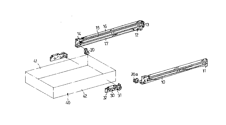
11 Fig. 1 is an exploded view of an improved track means
12 for drawers in accordance with the present invention;
13 Fig. 2 is a schematic side view of a drawer equipped
14 with the improved track means in accordance the present
invention;
16 Fig. 3 is a schematic fragmentary side view showing the
17 removal of the drawer from its accommodating space; and
18 Fig. 4 is a schematic view showing another embodiment
19 of the present invention for a wooden drawer.
DETAILED DESCRIPTION OF THE PREFERRED EMBODIMENTS
21 Referring to Figs. 1 and 2, a track means for drawers
22 according to the present invention comprises a pair of
23 spaced stationary tracks 10 securely mounted to longitudinal
2~ walls of a furniture (such as a desk) which define a space
for accommodating a drawer 40 and a pair of sliding members
26 30 securely mounted to outer longitudinal surfaces 42 of the
27 drawer 40 which face the stationary tracks 10.
28 Each stationary track 10 includes a strip 19 having an
29

_ 5 _ 2073~6~
1 upper flange 16 and a lower flange 17 respectively
2 protruding from an upper edge and a lower edge thereof,
3 thereby defining a sliding track 15 for the sliding member
4 30. The lower flange 17 extends over a length of the strip
19. The upper flange 16 extends from a rear end of the strip
6 19 and terminates at a position before a front stop 14,
7 leaving a passage located in front of the upper flange 17,
8 whose purpose will be explained hereinafter.
9 The sliding members 30 are mounted to both outer
longitudinal surfaces of the drawer 40 adjacent to a rear
11 end thereof. A roller 31 rotatably mounted on each of the
12 sliding members 30 is received and rotatable in the track
13 15, providing a smooth operation of the drawer 40. A block
14 20 is mounted to a front end of the stationary track 10 and
has a smooth upper surface 20a to support an underside of
16 the drawer 40, thereby providing a smooth supporting point
17 for the drawer 40 during operation.
18 A rear stop 13 is mounted to a rear end of the
19 stationary tracks 10 for preventing the drawer 40 from
moving out of the stationary tracks 10. The front stop 14 is
21 mounted to a front portion of the stationary tracks 10 for
22 limiting a distance of which the drawer 40 is pulled out.
23 This is achieved by a contact strip 32 provided on a front
24 end of the sliding member 30 so as to contact and to be
stopped by the front stop 13 of the stationary track 10 when
26 pulling out the drawer 40.
27 When the user wishes to completely remove the drawer 40
28 from the desk, he may first pull out the drawer until the
29
,

- 6 - 2073365
1 roller moves to a position shown in the phantom lines in
2 Fig. 3, and then lift the drawer upward as clearly shown in
3 Fig. 3 to allow the removal of the drawer 40 by the contact
4 strip 32 and the roller 31 passing through the passage in
front of the upper flange 17.
6 As shown in Fig. 2, the rear ends of the stationary
7 tracks 10 are slanted downward to insure the drawer 40 in
8 its closed position. Furthermore, a mounting standard tab 11
9 extends downward from a rear end of the stationary track 10,
providing a mounting standard for mounting the stationary
11 track to the walls of the desk. For example, the person
12 installing the drawer may draw a horizontal line on the wall
13 and then mount the tracX on the wall with a lowest point of
14 the front end thereof located on the line and the lowest
point of the strip 11. By this way, the track slants
16 downward from the front end thereof to the rear end thereof,
17 preventing the drawer from unintentionally sliding out from
18 its closed position.
19 Referring to Fig. 4, for a wooden drawer, a claw 33 and
a screw 34 can be used to further secure the sliding members
21 30 to both side walls 41 and 42 of the wooden drawer 40.
22 Although the invention has been explained in relation
23 to its preferred embodiment, it is to be understood that
24 many other possible modifications and variations can be made
without departing the spirit and scope of the invention as
26 hereinafter claimed.
27
28
29

Representative Drawing
A single figure which represents the drawing illustrating the invention.
Administrative Status

2024-08-01:As part of the Next Generation Patents (NGP) transition, the Canadian Patents Database (CPD) now contains a more detailed Event History, which replicates the Event Log of our new back-office solution.

Please note that "Inactive:" events refers to events no longer in use in our new back-office solution.

For a clearer understanding of the status of the application/patent presented on this page, the site Disclaimer , as well as the definitions for Patent , Event History , Maintenance Fee  and Payment History  should be consulted.

Event History

Description Date
Inactive: IPC expired 2017-01-01
Inactive: IPC from MCD 2006-03-11
Time Limit for Reversal Expired 1995-01-10
Application Not Reinstated by Deadline 1995-01-10
Deemed Abandoned - Failure to Respond to Maintenance Fee Notice 1994-07-11
Inactive: Adhoc Request Documented 1994-07-11
Application Published (Open to Public Inspection) 1994-01-11
All Requirements for Examination Determined Compliant 1992-07-10
Request for Examination Requirements Determined Compliant 1992-07-10

Abandonment History

Abandonment Date Reason Reinstatement Date
1994-07-11
Owners on Record

Note: Records showing the ownership history in alphabetical order.

Current Owners on Record
CHING T. LEE
Past Owners on Record
None
Past Owners that do not appear in the "Owners on Record" listing will appear in other documentation within the application.
Documents

To view selected files, please enter reCAPTCHA code :


To view images, click a link in the Document Description column. To download the documents, select one or more checkboxes in the first column and then click the "Download Selected in PDF format (Zip Archive)" or the "Download Selected as Single PDF" button.

List of published and non-published patent-specific documents on the CPD .

If you have any difficulty accessing content, you can call the Client Service Centre at 1-866-997-1936 or send them an e-mail at CIPO Client Service Centre.


Document
Description 
Date
(yyyy-mm-dd) 
Number of pages   Size of Image (KB) 
Cover Page 1994-01-11 1 10
Claims 1994-01-11 2 62
Abstract 1994-01-11 1 31
Drawings 1994-01-11 4 47
Descriptions 1994-01-11 5 170
Representative drawing 1998-07-30 1 19
Courtesy - Office Letter 1992-12-15 1 41