Sélection de la langue

Search

Sommaire du brevet 2073365 

Énoncé de désistement de responsabilité concernant l'information provenant de tiers

Une partie des informations de ce site Web a été fournie par des sources externes. Le gouvernement du Canada n'assume aucune responsabilité concernant la précision, l'actualité ou la fiabilité des informations fournies par les sources externes. Les utilisateurs qui désirent employer cette information devraient consulter directement la source des informations. Le contenu fourni par les sources externes n'est pas assujetti aux exigences sur les langues officielles, la protection des renseignements personnels et l'accessibilité.

Disponibilité de l'Abrégé et des Revendications

L'apparition de différences dans le texte et l'image des Revendications et de l'Abrégé dépend du moment auquel le document est publié. Les textes des Revendications et de l'Abrégé sont affichés :

  • lorsque la demande peut être examinée par le public;
  • lorsque le brevet est émis (délivrance).
(12) Demande de brevet: (11) CA 2073365
(54) Titre français: RAILS COULISSANTS POUR TIROIRS
(54) Titre anglais: TRACK MEANS FOR DRAWERS
Statut: Réputée abandonnée et au-delà du délai pour le rétablissement - en attente de la réponse à l’avis de communication rejetée
Données bibliographiques
Abrégés

Abrégé anglais


IMPROVED TRACK MEANS FOR DRAWERS
ABSTRACT
A track assembly for drawers includes a pair of spaced
stationary tracks securely mounted to longitudinal walls of
a piece of furniture which define a space for accommodating
a drawer and a pair of sliding members securely mounted to
outer longitudinal surfaces of the drawer which face the
stationary tracks. Each stationary track includes a strip
having an upper flange and a lower flange respectively
protruding from an upper edge and a lower edge thereof and
extending along a length thereof, thereby defining a sliding
track for the sliding member. The sliding members are
mounted to both outer longitudinal surfaces of the drawer
adjacent to a rear end thereof. A roller rotatably mounted
on each of the sliding members is received and rotatable in
the track, providing a smooth operation of the drawer. A
block is mounted to a front end of the stationary track and
has a smooth upper surface to support an underside of the
drawer, thereby providing a smooth supporting point for the
drawer during operation. A rear stop and a front stop are
respectively mounted to a rear end and a front end of the
stationary tracks for preventing the drawer from moving out
of the stationary tracks.

Revendications

Note : Les revendications sont présentées dans la langue officielle dans laquelle elles ont été soumises.


- 7 -
THE EMBODIMENTS OF THE INVENTION IN WHICH AN EXCLUSIVE
PROPERTY OR PRIVILEGE IS CLAIMED ARE DEFINED AS FOLLOWS:
1. An improved track means for drawers comprising a
pair of spaced stationary tracks securely mounted to
longitudinal walls of a piece of furniture which define a
space for accommodating a drawer and a pair of sliding
members securely mounted to outer longitudinal surfaces of
the drawer which face the stationary tracks,
each stationary track comprising a strip having an
upper flange and a lower flange respectively protruding from
an upper edge and a lower edge thereof and extending along a
length thereof, thereby defining a sliding track for said
sliding member,
said sliding members being mounted to both outer
longitudinal surfaces of said drawer adjacent to a rear end
thereof, a roller rotatably mounted on each of said sliding
members being received and rotatable in said track,
providing a smooth operation of said drawer, a block being
mounted to a front end of said stationary track and having a
smooth upper surface to support an underside of said drawer,
thereby providing a smooth supporting point for said drawer
during operation, and
a rear stop being mounted to a rear end of said
stationary tracks for preventing said drawer from moving out
of said stationary tracks, a front stop being mounted to a
front portion of said stationary tracks for limiting a
distance of which said drawer is pulled out.
2. The improved track means for drawers as claimed in
claim 1, wherein a contact strip is provided to a front end

- 8 -
of said sliding member so as to contact and to be stopped by
said front stop of said stationary track when pulling out
said drawer.
3. The improved track means for drawers as claimed in
claim 2, wherein said upper flange extends from a rear end
of said strip and terminates at a position before said front
stop, leaving a passage located in front of said upper
flange to allow the removal of said drawer by said contact
strip and said roller passing through said passage in front
of said upper flange.
4. An improved track means for drawers as claimed in
claim 1, wherein each said rear end of said stationary
tracks is slanted downward to insure said drawer in its
closed position.
5. An improved track means for drawers as claimed in
claim 1, wherein a mounting standard tab extends downward
from a rear end of said stationary track, providing a
mounting standard for mounting said stationary track to the
walls of the furniture.

Description

Note : Les descriptions sont présentées dans la langue officielle dans laquelle elles ont été soumises.

20~3~65
- 2 -
1 IMPROVED TRACK MEANS FOR DRAWERS
2 BACKGROUND OF TIIE INVENTION
3 The present invention relates to an improved track
4 means for drawers.
There are several well-known types of track means for
6 drawers. However, theses conventional track means have one
7 or more following disadvantages due to their structure: (1)
8 the drawer easily slides too far outward beyond the
9 compartment for the drawer when pulling out the drawer, (2)
assembly which is too involved, (3) difficult processing,
11 and (4) a high cost in manufacturing.
12 ~he present invention intends to provide an improved
13 track means to mitigate and/or obviate the above-mentioned
14 drawbacks.
SUMMARY OF THE INVENTION
16 A track means for drawers generally includes a pair of
17 spaced stationary tracks securely mounted to longitudinal
18 walls of a furniture, such as a desk, which define a space
19 for accommodating a drawer and a pair of sliding members
securely mounted to outer longitudinal surfaces of the
21 drawer which face the stationary tracks. According to one
22 aspect of the present invention, the track means is
23 characterized by that:
24 each stationary track includes a strip having an upper
flange and a lower flange respectively protruding from an
26 upper edge and a lower edge thereof and extending along a
27 length thereof, thereby defining a sliding track for the
28 sliding mem~er,
29
.

207336~
- 3 -
1 the sliding members are mounted to both outer
2 longitudinal surfaces of the drawer adjacent to a rear end
3 thereof, a roller rotatably mounted on each of the sliding
4 members is received and rotatable in the track, providing a
smooth operation of the drawer, a block is mounted to a
6 front end of the stationary track and has a smooth upper
7 surface to support an underside of the drawer, thereby
8 providing a smooth supporting point for the drawer during
9 operation, and
a rear stop is mounted to a rear end of the stationary
11 tracks for preventing the drawer from moving out of the
12 stationary tracks, a front stop is mounted to a front
13 portion of the stationary tracks for limiting a distance of
14 which the drawer is pulled out.
According to another aspect of the present inve~tion, a
16 contact strip is provided to a front end of the sliding
17 member so as to contact and to be stoppèd by the front stop
18 of the stationary track when pulling out the drawer.
19 According to still another aspect of the present
invention, the upper flange extends from a rear end of the
21 strip and terminates at a position before the front stop,
22 leaving a passage located in front of the upper flange to
23 allow the removal of the drawer by the contact strip and the
24 roller passing through the passage in front of the upper
flange.
26 According to yet another aspect of the present
27 invention, each rear end of the lower flange is slanted
28 downward to insure the drawer in its closed position.
~9
: .~ . ^.

207336~
1 Ac~ording to still another aspect of the present
2 invention, a mounting standard tab extends downward from a
3 rear end of the stationary track, providing a mounting
4 standard for mounting the stationary track to the walls of
the desk.
6 Other objects, advantages, and novel features of the
7 invention will become more apparent from the following
8 detailed description when taken in conjunction with the
9 accompanying drawings.
BRIEF DESCRIPTION OF THE DRAWINGS
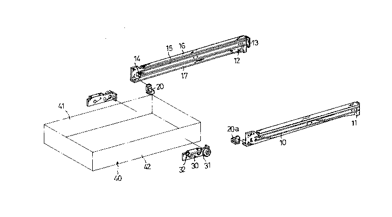
11 Fig. 1 is an exploded view of an improved track means
12 for drawers in accordance with the present invention;
13 Fig. 2 is a schematic side view of a drawer equipped
14 with the improved track means in accordance the present
invention;
16 Fig. 3 is a schematic fragmentary side view showing the
17 removal of the drawer from its accommodating space; and
18 Fig. 4 is a schematic view showing another embodiment
19 of the present invention for a wooden drawer.
DETAILED DESCRIPTION OF THE PREFERRED EMBODIMENTS
21 Referring to Figs. 1 and 2, a track means for drawers
22 according to the present invention comprises a pair of
23 spaced stationary tracks 10 securely mounted to longitudinal
2~ walls of a furniture (such as a desk) which define a space
for accommodating a drawer 40 and a pair of sliding members
26 30 securely mounted to outer longitudinal surfaces 42 of the
27 drawer 40 which face the stationary tracks 10.
28 Each stationary track 10 includes a strip 19 having an
29

_ 5 _ 2073~6~
1 upper flange 16 and a lower flange 17 respectively
2 protruding from an upper edge and a lower edge thereof,
3 thereby defining a sliding track 15 for the sliding member
4 30. The lower flange 17 extends over a length of the strip
19. The upper flange 16 extends from a rear end of the strip
6 19 and terminates at a position before a front stop 14,
7 leaving a passage located in front of the upper flange 17,
8 whose purpose will be explained hereinafter.
9 The sliding members 30 are mounted to both outer
longitudinal surfaces of the drawer 40 adjacent to a rear
11 end thereof. A roller 31 rotatably mounted on each of the
12 sliding members 30 is received and rotatable in the track
13 15, providing a smooth operation of the drawer 40. A block
14 20 is mounted to a front end of the stationary track 10 and
has a smooth upper surface 20a to support an underside of
16 the drawer 40, thereby providing a smooth supporting point
17 for the drawer 40 during operation.
18 A rear stop 13 is mounted to a rear end of the
19 stationary tracks 10 for preventing the drawer 40 from
moving out of the stationary tracks 10. The front stop 14 is
21 mounted to a front portion of the stationary tracks 10 for
22 limiting a distance of which the drawer 40 is pulled out.
23 This is achieved by a contact strip 32 provided on a front
24 end of the sliding member 30 so as to contact and to be
stopped by the front stop 13 of the stationary track 10 when
26 pulling out the drawer 40.
27 When the user wishes to completely remove the drawer 40
28 from the desk, he may first pull out the drawer until the
29
,

- 6 - 2073365
1 roller moves to a position shown in the phantom lines in
2 Fig. 3, and then lift the drawer upward as clearly shown in
3 Fig. 3 to allow the removal of the drawer 40 by the contact
4 strip 32 and the roller 31 passing through the passage in
front of the upper flange 17.
6 As shown in Fig. 2, the rear ends of the stationary
7 tracks 10 are slanted downward to insure the drawer 40 in
8 its closed position. Furthermore, a mounting standard tab 11
9 extends downward from a rear end of the stationary track 10,
providing a mounting standard for mounting the stationary
11 track to the walls of the desk. For example, the person
12 installing the drawer may draw a horizontal line on the wall
13 and then mount the tracX on the wall with a lowest point of
14 the front end thereof located on the line and the lowest
point of the strip 11. By this way, the track slants
16 downward from the front end thereof to the rear end thereof,
17 preventing the drawer from unintentionally sliding out from
18 its closed position.
19 Referring to Fig. 4, for a wooden drawer, a claw 33 and
a screw 34 can be used to further secure the sliding members
21 30 to both side walls 41 and 42 of the wooden drawer 40.
22 Although the invention has been explained in relation
23 to its preferred embodiment, it is to be understood that
24 many other possible modifications and variations can be made
without departing the spirit and scope of the invention as
26 hereinafter claimed.
27
28
29

Dessin représentatif
Une figure unique qui représente un dessin illustrant l'invention.
États administratifs

2024-08-01 : Dans le cadre de la transition vers les Brevets de nouvelle génération (BNG), la base de données sur les brevets canadiens (BDBC) contient désormais un Historique d'événement plus détaillé, qui reproduit le Journal des événements de notre nouvelle solution interne.

Veuillez noter que les événements débutant par « Inactive : » se réfèrent à des événements qui ne sont plus utilisés dans notre nouvelle solution interne.

Pour une meilleure compréhension de l'état de la demande ou brevet qui figure sur cette page, la rubrique Mise en garde , et les descriptions de Brevet , Historique d'événement , Taxes périodiques et Historique des paiements devraient être consultées.

Historique d'événement

Description Date
Inactive : CIB expirée 2017-01-01
Inactive : CIB de MCD 2006-03-11
Le délai pour l'annulation est expiré 1995-01-10
Demande non rétablie avant l'échéance 1995-01-10
Réputée abandonnée - omission de répondre à un avis sur les taxes pour le maintien en état 1994-07-11
Inactive : Demande ad hoc documentée 1994-07-11
Demande publiée (accessible au public) 1994-01-11
Toutes les exigences pour l'examen - jugée conforme 1992-07-10
Exigences pour une requête d'examen - jugée conforme 1992-07-10

Historique d'abandonnement

Date d'abandonnement Raison Date de rétablissement
1994-07-11
Titulaires au dossier

Les titulaires actuels et antérieures au dossier sont affichés en ordre alphabétique.

Titulaires actuels au dossier
CHING T. LEE
Titulaires antérieures au dossier
S.O.
Les propriétaires antérieurs qui ne figurent pas dans la liste des « Propriétaires au dossier » apparaîtront dans d'autres documents au dossier.
Documents

Pour visionner les fichiers sélectionnés, entrer le code reCAPTCHA :


Pour visualiser une image, cliquer sur un lien dans la colonne description du document. Pour télécharger l'image (les images), cliquer l'une ou plusieurs cases à cocher dans la première colonne et ensuite cliquer sur le bouton "Télécharger sélection en format PDF (archive Zip)" ou le bouton "Télécharger sélection (en un fichier PDF fusionné)".

Liste des documents de brevet publiés et non publiés sur la BDBC .

Si vous avez des difficultés à accéder au contenu, veuillez communiquer avec le Centre de services à la clientèle au 1-866-997-1936, ou envoyer un courriel au Centre de service à la clientèle de l'OPIC.


Description du
Document 
Date
(aaaa-mm-jj) 
Nombre de pages   Taille de l'image (Ko) 
Page couverture 1994-01-11 1 10
Revendications 1994-01-11 2 62
Abrégé 1994-01-11 1 31
Dessins 1994-01-11 4 47
Description 1994-01-11 5 170
Dessin représentatif 1998-07-30 1 19
Courtoisie - Lettre du bureau 1992-12-15 1 41