Note: Descriptions are shown in the official language in which they were submitted.
PATENT
FIELD OF THE INVENTION
The present invention relates to a nonwoven fibrous
material and a method of making the same.
BACKGROUND OF THE INVENTION
In the past, nonwoven webs of meltblown fibers formed
- using conventional techniques have been considered to be
relatively isotropic, especially when compared to nonwoven
webs such as, for example, bonded carded webs. The
isotropic properties of nonwoven meltblown fiber webs have
been considered advantageous in situations where nonwoven
web must withstand forces applied in more than one
direction.
However, in some situations nonwoven webs of meltblown
fibers are subjected to forces applied in only one
direction. Thus, it would be desirable to have a nonwoven
web of meltblown fibers that is anisotropic. That is, the
nonwoven web of meltblown fibers could have different
physical properties (e.g., strength, and/or stretch and
recovery) in different direction. For example, it would be
desirable to have a nonwoven web of meltblown fibers
possessing specified levels of physical properties in only
the direction that those properties were needed.
An exemplary situation where such an anisotropic
nonwoven web of meltblown fibers would be desirable is in
certain types of elastomeric composite materials referred
to as stretch-bonded laminates. A stretch-bonded laminate
is made by joining a nonelastic material to an elastic
sheet while the elastic sheet is in a stretched condition
so that when the elastic sheet is relaxed, the nonelastic
material gathers between the locations where it is bonded
to the elastic sheet. The resulting material is
stretchable to the extent that the nonelastic material
gathered between the bond locations allows the elastic
sheet to elongate. An example of this type of material is
disclosed, for example, by U.S. Patent No. 4,720,415 to
Vander Wielen et al., issued January 19, 1988.
:.. .
~ z ~ ~ ? ~ 9 9
In many applications, stretch bonded laminates are
adapted to stretch and recover ln only one direction such
as, for example, the machine direction. Thus, the elastic
component of the laminate does not have to be isotropic.
That is, the elastic component need not have the same
stretch and recovery properties in every direction.
Desirably, the elastic component would have the required
stretch and recovery properties in only the direction that
the gathered nonelastic material allows the laminate to
stretch. For example, if the fibers of an elastomeric web
of meltblown fibers were generally aligned in only one
direction to provide a specified measure of one or more
physical properties, such as tension, in that one
direction, then relatively fewer elastomeric meltblown
fibers could be used than if the web was isotropic. Since
elastomeric materials generally tend to be quite expensive,
reducing the amount of elastomeric material while still
i achieving the desired physical properties would be
desirable. This is an important consideration since
nonwoven webs of meltblown fibers can be used as economical
and efficient substitutes for woven or knit textile
materials and, in some cases, nonwoven materials such as
bonded carded webs. For example, nonwoven webs of
meltblown fibers are particularly useful in certain
applications in garment materials, pads, diapers and
personal care products where an item may be manufactured so
inexpensively that it may be economical to discard the
- product after only one or a limited number of uses.
Although anisotropic nonwoven webs of meltblown fibers
are disclosed by U.S. Patent No. 4,656,081, those webs can
be characterized by a heterogenous arrangement of fibers
and fiber bundles. In particular, that patent discloses a
material having a heterogenous organization in that yarn-
like fiber bundles outnumber the fine fibers on one surface
; 35 of the material and fine fibers outnumber the yarn-like
fiber bundles on the other surface of the material. While
U.S. Patent No. 4,656,081 indicates that the material may
~9
be made by melt-blowing processes, the heterogenous nature
of the material and the presence of yarn-like fiber bundles
indicate relative poor web formation which may yield poor
web properties that offset any advantage obtained by
orienting the fibers.
Accordingly, there is still a need for an anisotropic
nonwoven web having a substantially homogenous arrangement
of meltblown fibers generally aligned in oneof the planar
dimensions of the web. Additionally, there is still a need
for an inexpensive composite elastic material which is
suited for high-speed manufacturing processes and which
contains an elastic component that provides the desired
elastic properties to the composite only in the one
direction of stretch and recovery.
DEFINITIONS
The term "elastic" is used herein to mean any material
which, upon application of a biasing force, is stretchable,
that is, elongatable at least about 60 percent (i.e., to a
stretched, biased length which is at least about 160
percent of its relaxed unbiased length), and which, will
recover at least 55 percent of its elongation upon release
of the stretching, elongating force. A hypothetical
example would be a one (1) inch sample of a material which
is elongatable to at least 1.60 inches and which, upon
being elongated to 1.60 inches and released, will recover
to a length of not more than 1.27 inches. Many elastic
materials may be elongated by much more than 60 percent
(i.e., much more than 160 percent of their relaxed length),
for example, elongated lOO percent or more, and many of
these will recover to substantially their initial relaxed
length, for example, to within 105 percent of their
original relaxed length, upon release of the stretching
force.
The term "nonelastic" as used herein refers to any
material which does not fall within the definition of
~; "elastic," above.
,`
'
,, .
.
Z~7~9
The terms "recover" and "recovery" as used herein refer
to a contraction of a stretched material upon termination
of a biasing force following stretching of the material by
application of the biasing force. For example, if a
material having a relaxed, unbiased length of one ~1) inch
is elongated 50 percent by stretching to a length of one
and one half (1.5) inches, the material would be elongated
50 percent (0.5 inch) and would have a stretched length
that is 150 percent of its relaxed length. If this
; 10 exemplary stretched material contracted, that is recovered
to a length of one and one tenth (1.1) inches after release
. of the biasing and stretching force, the material would
,~ have recovered 80 percent tO.4 inch) of its one-half (0.5)
; inch elongation. Recovery may be expressed as [(maximum
stretch length - final sample length)/(maximum stretch
length - initial sample length)] X 100.
The term "machine direction" as used herein refers to
the planar dimension of a nonwoven fibrous web which is in
the direction of travel of the forming surface onto which
fibers are deposited during formation of the web.
The term "cross-machine direction" as used herein refers
to the planar dimension of a nonwoven fibrous web which is
in the direction that is perpendicular to the machine
direction defined above.
The term "strength index" as used herein means a ratio
of the peak load of a material in the machine direction
; (MD) with the peak load of that same material in the cross-
machine direction (CD). The term is also meant to
encompass a ratio of the tensile load in the machine
direction (MD) at a given elongation with the tensile load
of that same material in the cross-machine direction (CD)
at the same elongation. Typically, the strength index may
be determined from a ratio of the peak load in both the
machine and cross-machine directions. In that case, the
strength index may be expressed by the following equation:
strer~th ir,dex = ~MD peak load/CD peak load)
2~ 99
s
A material having a machine direction (MD) peak load (or
tensile load at a specified elongation) greater than its
cross-machine direction (CD) peak load (or tensile load at
the same elongation) will have a strength index that is
greater than one (1). A material having a machine
direction peak load (or tensile load at a specified
elongation) less than its cross-machine direction peak load
(or tensile load at the same elongation) will have a
strength index that is less than one (1).
The term "isotropic" as used herein refers to a material
characterized by a strength index ranging from about 0.5 to
about two (2).
The term "anisotropic" as used herein refers to a
material characterized by a strength index which is less
than about 0.5 or greater than about two (2). For example,
an anisotropic nonwoven web may have a strength index of
about 0.25 or about three (3).
The term "substantially homogenous" as used herein
refers to uniform and even distribution of fibrous material
within a nonwoven fibrous web such that each face of the
nonwoven fibrous web contains about the same mixture of
fibrous materials. An example of such a substantially
homogenous web may be seen in FIGS. 3 through 6 in which
there is little or no observable difference between the
mixture of fibrous materials present on the wire side and
the die tip side of the illustrated anisotropic nonwoven
webs of meltblown fibers. An example of a material which
is not substantially homogenous is illustrated by U.S.
Patent No. 4,656,081.
The term "composite elastic material" as used herein
refers to a multilayer material having at least one elastic
layer joined to at least one gatherable layer at least at
two locations in which the gatherable layer is gathered
between the locations where it is joined to the elastic
layer. A composite elastic material may be stretched to
the extent that the nonelastic material gathered between
the bond locations allows the elastic material to elongate.
;'
~'
.
X~ 9
This type of composite elastic material is disclosed, for
example, by U.S. Patent No. 4,720,415 to Vander Wielen et
al., issued January 19, 1988, which is hereby incorporated
by reference.
The term "stretch-to-stop" as used hereln refers to a
ratio determined from the difference between the unextended
dimension of a composite elastic material and the maximum
extended dimension of a composite elastic material upon the
application of a specified tensioning force and dividing
that difference by the unextended dimension of the
composite elastic material. If the stretch-to-stop is
expressed in percent, this ratio is multiplied by 100. For
example, a composite elastic material having an unextended
length of 5 inches and a maximum extended length of 10
inches upon applying a force of 2000 grams has a stretch-
to-stop (at 2000 grams) of 100 percent. Stretch-to-stop
may also be referred to as "maximum non-destructive
elongation". Unless specified otherwise, stretch-to-stop
values are reported herein at a load of 2000 grams.
The term "tenacity" as used herein refers to the
resistance to elongation of a composite elastic material
which is provided by its elastic component. Tenacity is
; the tensile load of a composite elastic material at a
specified strain (i.e., elongation) for a given width of
material divided by the basis weight of that composite
material's elastic component as measured at about the
composite material's stretch-to-stop elongation. For
example, tenacity of a composite elastic material is
typically determined in one direction (e.g., machine
direction) at about the composite material's stretch-to-
stop elongation. Elastic materials having high values for
tenacity are desirable in certain applications because less
material is needed to provide a specified resistance to
elongation than a low tenacity material. For a specified
sample width, tenacity is reported in units of force
divided by the units of basis weight of the elastic
component. This provides a measure of force per unit area
~77~9
and is accomplished by reporting the thickness of tha
elastic component in terms of its basis weight rather than
` as an actual caliper measurement. For example, reported
units may be grams force (for a specific sample width)/grams
per square meter. Unless specified otherwise, all tenacity
data is reported for the first extension of a three (3)
inch wide sample having a four (4) inch gauge length.
As used herein, the term "nonwoven web" means a web
having a structure of individual fibers or threads which
are interlaid, but not in an identifiable, repeating
manner. Nonwoven webs have been, in the past, formed by a
variety of processes such as, for example, meltblowing
processes, spunbonding processes and bonded carded web
processes.
As used herein, the term "autogenous bonding" means
bonding provided by fusion and/or self-adhesion of fibers
and/or filaments without an applied external adhesive or
bonding agent. Autogenous bonding may be provided by
contact between fibers and/or filaments while at least a
portion of the fibers and/or filaments are semi-molten or
tacky. Autogenous bonding may also be provided by blending
a tackifying resin with the thermoplastic polymers used to
form the fibers and/or filaments. Fibers and/or filaments
formed from such a blend can be adapted to self-bond with
or without the application of pressure and/or heat.
Solvents may also be used to cause fusion of fibers and
filaments which remains after the solvent is removed.
As used herein, the term "meltblown fibers" means fibers
formed by extruding a molten thermoplastic material through
a plurality of fine, usually circular, die capillaries as
molten threads or filaments into a high velocity gas (e.g.
air) stream which attenuates the filaments of molten
thermoplastic material to reduce their diameter, which may
~ be to microfiber diameter. Thereafter, the meltblown
; 35 fibers are carried by the high velocity gas stream and are
deposited on a collecting surface to form a web of randomly
disbursed meltblown fibers. Such a process is disclosed,
.
~;
~'i'` .
,. .
.
~ . .
:. ~
2~7~t~g9
t 8
for example, in U.S. Patent No. 3,849,241 to Butin, the
disclosure of which is hereby incorporated by reference.
As used herein, the term "microfibers" means small
diameter fibers having an average diameter not greater than
about 100 microns, for example, having an average diameter
of from about 0.5 microns to about 50 microns, or more
particularly, microfibers may have an average diameter of
from about 4 microns to about 40 microns.
As used herein, the term "spunbonded fibers" refers to
small diameter fibers which are formed by extruding a
molten thermoplastic material as filaments from a plurality
of fine, usually circular, capillaries of a spinnerette
with the diameter of the extruded filaments then being
rapidly reduced as by, for example, eductive drawing or
other well-known spun-bonding mechanisms. The production
of spun-bonded nonwoven webs is illustrated in patents such
as, for example, in U.S. Patent No. 4,340,563 to Appel et
al., and U.S. Patent No. 3,692,618 to Dorschner et al. The
disclosures of these patents are hereby incorporated by
reference.
As used herein, the term "polymer" generally includes,
but is not limited to, homopolymers, copolymers, such as,
for example, block, graft, random and alternating
copolymers, terpolymers, etc. and blends and modifications
; 25 thereof. Furthermore, unless otherwise specifically
limited, the term "polymer" shall include all possible
geometrical configurations of the material. These
configurations include, but are not limited to, isotactic,
syndiotactic and random symmetries.
As used herein, the term "superabsorbent" refers to
absorbent materials capable of absorbing at least 10 grams
of agueous liquid (e.g. distilled water per gram of
absorbent material while immersed in the liquid for 4 hours
and holding substantially all of the absorbed liquid while
under a compression force of up to about 1.5 psi.
As used herein, the term "consisting essentially of"
~ does not exclude the presence of additional materials which
.;":
'
:
.
... ; .. . .
~ . .
.:
:, ' .
,, . . ~ :
Z~ 9
do not significantly affect the desired characteristics of
a given composition or product. Exemplary materials of
this sort would include, without limitation, pigments,
antioxidants, stabilizers, surfactants, waxes, flow
promoters, particulates and materials added to enhance
processability of the composition.
SUMMARY OF THE INVENTION
Problems associated with previous nonwoven webs have
been addressed by the anisotropic nonwoven web meltblown
fibers of the present invention. The anisotropic nonwoven
fibrous web is composed of a substantially homogenous
distribution of meltblown fibers which are generally
aligned in one planar dimension of the web such as, for
example, the machine direction of the web. The present
- invention also encompasses a process of making an
anisotropic nonwoven fibrous web containing a substantially
homogenous arrangement of meltblown fibers which are
generally aligned along one planar dimension of the web.
Generàlly speaking, the process includes the steps of:
providing a stream of gas-borne meltblown fibers; and
directing the stream of meltblown fibers onto a forming
surface at a contact angle from about 10 to about 60
degrees to the forming surface with minimum dispersion of
the gas-borne meltblown fibers. For example, the first
stream may be deflected to an angle from about 25 to about
45 degrees to the forming surface to produce the
anisotropic web of meltblown fibers that are generally
aligned along one planar dimension of the web, e.g., the
machine direction of the web. Generally speaking,
deflecting the stream of gas-borne meltblown fibers may be
accomplished by any technique which provide a shallow
contact angle with minimum dispersion of the gas-borne
meltblown fibers. For example, a first stream of gas-borne
meltblown fibers may be deflected at an impingement point
above the forming surface with a second stream of gas to
the desired angle. Alternatively and/or additionally, the
:, ~
'''
.
~,., ", , , ! . .
,
Z~?7~ 9
.. 10
meltblown die head and/or the forming surface may be
slanted to produce the desired contact angle. Generally
speaking, dispersion of the stream of gas-borne meltblown
fibers may be minimized by selecting a proper forming
distance and controlling air suction beneath the forming
surface. Where the steam of gas-borne meltblown fibers is
deflected by a second gas stream, dispersion can be
minimized by properly selecting a point of impingement.
In another aspect of the process of the present
invention, the anisotropic nonwoven fibrous web may be
formed directly upon at least one layer of a material such
as, for example, a knit fabric, woven fabric and/or
nonwoven fabric. The nonwoven fabric may be, for example,
an elastomeric web of meltblown fibers.
The meltblown fibers of an anisotropic web may be a
polymer selected from the group consisting of elastomeric
and non-elastomeric thermoplastic polymers. The non-
elastomeric polymer may be any suitable fiber forming resin
including, for example, polyolefins, non-elastomeric
polyesters, non-elastomeric polyamides, and cellulosic
derived polymers. The elastomeric polymer may be any
suitable elastomeric fiber forming resin including, for
example, elastomeric polymers such as elastic polyesters,
elastic polyurethanes, elastic polyamides, elastic
copolymers of ethylene and at least one vinyl monomer, and
elastic A-B-A' block copolymers wherein A and A' are the
same or different thermoplastic polymer, and wherein B is
an elastomeric polymer block. These resins may be blended
with a variety of additives and processing aids to produce
desired characteristics.
According to one aspect of the present invention, the
anisotropic nonwoven fibrous web may have a strength index
of more than 2. More particularly, the anisotropic fibrous
web may have a strength index of more than about 3. The
anisotropic web of the present invention may have a basis
weight of, for example, from about 10 to about 400 gsm.
More particularly, the web may have a basis weight of from
. :
.:,
~.
;
.~ ,
~7~ 9
11
- about 20 to about 200 gsm. Even more particularly, the web
may have a basis weight of from about 30 to about 50 gsm.
In one aspect of the present invention, the anisotropic
web of meltblown fibers may contain a mixture of meltblown
fibers and one or more other materials such as, for
example, wood pulp, nonelastic fibers, particulates or
super-absorbent materials and/or blends of such materials.
According to the present invention, the anisotropic
nonwoven web of meltblown fibers may be incorporated into
a multilayer material. For example, the anisotropic web
may be joined with at least one other textile fabric, knit
fabric, nonwoven fabric, film or combination thereof. As
a further example, if the anisotropic web is an elastomeric
web of meltblown fibers, it may be a component of a
composite elastic material in which the elastomeric web is
joined to a gatherable layer at spaced apart locations so
that the gatherable layer is gathered between the spaced-
apart locations.
Generally speaking, it is desirable that the anisotropic
; 20 elastomeric web component of such a composite elastic
~ material have a machine direction tenacity (one inch wide
; strip) of at least about 14 gramsfOrce/grams per square meter
at about the material's stretch-to-stop elongation. For
ëxample, the anisotropic elastomeric web component may have
a machine direction tenacity (one inch wide strip) ranging
from about 15 to about 30 gramsfO,ce/grams per square meter
at about the material's stretch-to-stop elongation.
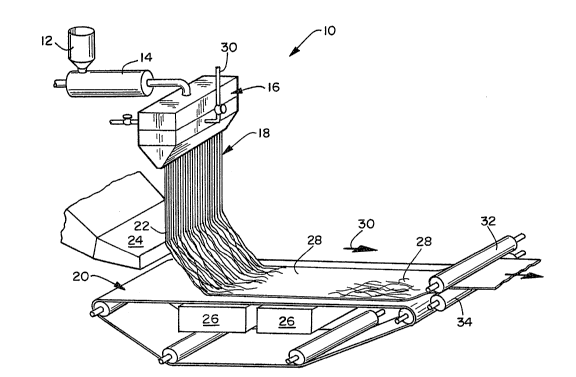
~; BRIEF DESCRIPTION OF THE DRAWINGS
FIG. 1 is a schematic drawing of an exemplary process
, , j
for forming an anisotropic elastic web of meltblown fibers.
FIG. 2 is a photomicrograph of an isotropic nonwoven web
containing a generally isotropic nonwoven web of randomly
distributed meltblown fibers.
FIG. 3 is a photomicrograph of an exemplary anisotropic
nonwoven web containing a substantially homogenous
:
:
:` :., . ~ .
,, : ; , :~ '
. . .
l2 2~ 9
distribution of meltblown fibers that are generally aligned
along the machine direction of the web.
FIG. 4 is a photomicrograph of an exemplary anisotropic
nonwoven web containing a substantially homogenous
; 5 distribution of meltblown fibers that are generally aligned
along the machine direction of the web.
FIG. 5 is a photomicrograph of an exemplary anisotropic
nonwoven web containing a substantially homogenous
distribution of meltblown fibers that are generally aligned
along the machine direction of the web.
FIG. 6 is a photomicrograph of an exemplary anisotropic
; nonwoven web containing a substantially homogenous
distribution of meltblown fibers that are generally aligned
along the machine direction of the web.
FIG. 7 is a graph of load versus elongation determined
during tensile testing of an exemplary stretch-bonded
laminate.
DETAILED DESCRIPTION OF THE INVENTION
The present invention provides an anisotropic nonwoven
web containing a substantially homogenous distribution of
meltblown fibers generally aligned in a similar direction.
For example, the anisotropic nonwoven web is composed of a
substantially homogenous distribution of meltblown fibers
which are generally aligned along one planar dimension of
~ the web, e.g., the machine direction of the web.
; Referring now to the drawings wherein like reference
numerals represent the same or equivalent structure and, in
particular, to FIG. 1 of the drawings, there is
schematically illustrated at 10 an exemplary process of
making an anisotropic nonwoven fibrous web containing a
substantially homogenous arrangement of meltblown fibers
i generally aligned along one planar dimension of the web,
e.g., the machine direction of the web. Generally
speaking, the process includes the steps of: (1) providing
~`~ a stream of gas-borne meltblown fibers; and (2) directing
the stream of meltblown fibers so that the stream contacts
,,
,
~":
.~
,
2~7~ 39
a forming surface at an angle from about 10 to about 60
degrees to the forming surface with minimum dispersion of
the gas-borne fibers. It is contemplated that the stream
of gas-borne meltblown fibers may be formed utilizing a
variety of conventional meltblowing techniques. Meltblowing
techniques generally involve extruding a thermoplastic
polymer resin through a plurality of small diameter
capillaries of a meltblowing die as molten threads into a
heated gas stream (the primary air stream) which is flowing
generally in the same direction as that of the extruded
threads so that the extruded threads are attenuated, i.e.,
drawn or extended, to reduce their diameter. Such
meltblowing techniques, and apparatus therefor, are
discussed fully in U.S. Patent No. 4,663,220, the contents
of which are incorporated herein by reference. In forming
the fibers used in the fibrous web, pellets or chips/ etc.
(not shown) of an extrudable polymer are introduced into a
pellet hopper 12 of an extruder 14.
The extruder has an extrusion screw (not shown) which
is driven by a conventional drive motor (not shown). As
the polymer advances through the extruder, due to rotation
; of the extrusion screw by the drive motor, it is
~ progressively heated to a molten state. Heating the
;~` polymer to the molten state may be accomplished in a
plurality of discrete steps with its temperature being
gradually elevated as it advances through discrete heating
zones of the extruder 14 toward a meltblowing die 16. The
meltblowing die 16 may be yet another heating zone where
the temperature of the thermoplastic resin is maintained at
an elevated level for extrusion. Heating of the various
zones of the extruder 14 and the meltblowing die may be
achieved by any of a variety of conventional heating
arrangements ~not shown).
In the meltblown die arrangement 16, the position of air
plates which, in conjunction with a die portion define
; chambers and gaps. Streams of attenuating gas converge to
form a primary stream of gas which entrains and attenuates
. .
.,
,
2~,5
., 1~
the molten threads, as they exit the orifices, into gas-
borne fibers 18 or, depending upon the degree of
attenuation, microfibers, of a small diameter which is
usually less than the diameter of the orifices.
The primary stream of gas is typically a heated gas
stream. For example, the gas stream may be heated to a
temperature of ranging from about 250 to about 600 degrees
Fahrenheit. The pressure of the primary stream of gas may
be adjusted so that it is powerful enough to attenuate the
extruded polymer threads into fibers and yet avoid
undesirable dispersion and scattering of the fibers when
the fibers are collected into a coherent nonwoven web. For
example, the pressure of the primary air stream may range
from about 0.25 to about 15 pounds per square inch, gauge.
When the primary gas stream is impinged by a secondary gas
stream, the pressure of the primary air stream is desirably
about 0.5 to about 1.5 psi. More particularly, the
pressure of the primary air stream may be about 1.0 psi.
In one embodiment, the gas-borne fibers or microfibers
18 are blown, by the action of the attenuating gas, toward
a collecting arrangement which, in the embodiment
illustrated in FIG. 1, is a foraminous endless belt 20.
The gas-borne fibers and microfibers 18 from die
arrangement 10 are impinged by a secondary gas stream 22
exiting an air duct 24 before the gas-borne fibers or
microfibers 18 reach the foraminous endless belt 20. The
secondary gas stream 22 deflects the stream of gas-borne
fibers or microfibers 18 at an angle to the belt 20.
The secondary gas stream 22 may be, for example, an air
stream generated by fans that supply a ~uench air stream to
the meltblowing apparatus through an air duct. The
secondary gas stream 22 may also be compressed air or any
other gas which is compatible with the meltblown fibers and
may be released via an orifice or nozzle. It is
contemplated that additives and/or other materials may be
entrained in the secondary gas stream to treat the
meltblown fibers
Air pressure in the air duct 24 is maintained at a level
sufficient to cause the stream of meltblown fibers and
microfibers 18 to deflect when that stream is impinged by
the secondary air stream 22. For example, the air pressure
in the air duct 24 may range from about 2 to about 5 inches
of water column. More particularly, the air pressure may
be at a setting of about 3.5 inches of water column. The
velocity of the secondary air stream 22 as it exits the air
duct 24 is also adjusted to provide sufficient energy to
deflect the stream of meltblown fibers and microfibers 24.
For example, the velocity of the secondary air stream 22
may range from about 8,000 to about 16,000 feet per minute.
Desirably, the velocity of the secondary air stream 22 is
at about 12,000 feet per minute. In one embodiment of the
invention, the width of the secondary air nozzle is about
one-half inch and the length of the nozzle is about the
same length as the meltblowing die itself.
The exit orifice or nozzle of the air duct 24
,,
transporting the secondary air stream 22 may be located,
for example, from about 1.5 to 5 inches off to one side of
the stream of meltblown fibers and microfibers 18.
Desirably, the nozzle may be located from about 2.5 to
about 3.5 inches from the stream of meltblown fibers and
microfibers 18.
The impingement point (i.e., the point where the
secondary air stream 22 impacts the stream of meltblown
fibers and microfibers 18) should be located so that the
deflected stream had only a minimum distance to travel to
reach the forming surface to minimize dispersion of the
entrained fibers and microfibers. For example, the
distance from the impingement point to the forming surface
may range from about 2 to about 12 inches. Desirably, the
distance from ~he impingement point to the forming surface
may range from about 5 to about 8 inches. The distance
from the impingement point to the meltblowing die tip
should also be set at a distance which minimizes dispersion
: of the stream of fibers and microfibers. For example, this
: .
"` Z~7''?ir-6~39
16
distance may range from about 2 to about 8 inches.
Desirably, this distance may be about 4 inches.
Generally speaking, the dispersion of the stream of gas-
borne meltblown fibers 18 may be minimized by selecting a
proper vertical forming distance before the stream of
fibers contacts the forming surface. A shorter vertical
forming distance is generally desirable for minimizing
dispersion. This must be balanced by the need for the
extruded fibers to solidify from their tacky, semi-molten
state before contacting the forming surface 20. For
example, the vertical forming distance may range from about
3 to about lS inches from the meltblown die tip.
Desirably, this vertical distance may be about 7 to about
ll inches from the die tip.
In some situations, it may be desirable to cool the
secondary air stream 22. Cooling the secondary air stream
; could accelerate the quenching of the molten or tacky
meltblown fibers and provide for shorter distances between
the meltblowing die tip and the forming surface which could
be used to minimize fiber dispersion and enhance the
substantially homogenous distribution of the generally
;; aligned meltblown fibers that form the web. For example,
the temperature of the secondary air stream 22 may be
cooled to about lS to about 85 degrees Fahrenheit.
Using the secondary air stream 22 as described above,
and also adjusting the meltblowing jet primary air stream
yields a deflected gas-borne stream of meltblown fibers and
microfibers 18. By this balancinq of primary and secondary
air pressures, the desired angle of impingement of
meltblown fibers to the wire may be obtained, resulting in
increased machine direction orientation while retaining a
substantially homogenous distribution of meltblown fibers.
Dispersion may also be minimized by controlling air
suction beneath the forming surface. It is desirable to
use vacuum boxes 26 beneath the forming surface to draw the
meltblown fibers or microfibers onto the forming surface.
~`''' .,
~ 9
17
The vacuum may be set at about l to about 4 inches of water
column.
The meltblown fibers are collected as a coherent
nonwoven we~ 28 on the surface of the foraminous endless
belt 20 which is rotating as indicated by the arrow 30 in
FIG. l. At least a portion of the entangled fibers or
microfibers 18 autogenously bond to other fibers or
microfibers because they are still somewhat tacky or molten
while they are deposited on the endless belt 20. It may be
desirable to lightly calender the anisotropic fibrous web
of meltblown fibers 28 in order to enhance the autogenous
bonding. This calendering may be accomplished with a pair
of patterned or un-patterned pinch rollers 32 and 34 under
sufficient pressure (and temperature, if desired) to cause
permanent autogenous bonding between the meltblown fibers.
The contact angle or angle between the stream of gas-
borne fibers and the endless belt 20 may range from about
lO to about 60 degrees. For example, the stream of gas-
borne fibers may be deflected so that it contacts the belt
25 at an angle from about 20 to about ~5 degrees. More
particularly, the stream of gas-borne fibers may be
deflected so that it contacts the belt 26 at an angle from
about 30 to about 35 degrees.
Of course, the stream of gas-borne meltblown fibers may
be deflected by any technique which provides a shallow
contact angle with minimum dispersion of the gas-borne
meltblown fibers, and the process of the present invention
should not be limited only to a technique in which a first
stream of gas-borne meltblown fibers 18 is deflected at an
impingement point above the forming surface with a
secondary gas stream 22. Alternatively and/or
additionally, the meltblown die arrangement 16 and/or the
forming surface 20 may be slanted to produce the desired
contact angle. For example, the stream o~ gas-borne
meltblown fibers or microfibers 18 may be directed toward
the belt 20 at an angle other than 90 degrees. If desired,
the stream of meltblown fibers or microfibers 18 may then
2'~t?~ 9
18
be impinged by the secondary gas stream 22 to deflect the
meltblown fibers or microfibers 18 before they are
collected on the foraminous endless belt 20. As a further
example, the foraminous endless belt 20 may be adjusted so
that it is positioned at an angle to the direction of the
stream of gas-borne fibers 18.
Although the inventors should not be held to a
particular theory of operation, it is believed that
deflecting a stream of gas-borne fibers or microfibers to
contact a foraminous endless belt under controlled vacuum
conditions provides a coherent, substantially homogenous
nonwoven web of meltblown fibers or microfibers generally
aligned along one planar dimension of the web, e.g., the
machine direction of the web, at least because (1) minimum
dispersion of the stream of gas-borne of meltblown fibers
can be achieved by using a second gas stream to deflect the
;; gas-borne fibers or microfibers; ~2) the second gas stream
acts to help align the gas-borne fibers in generally one
direction; (3) the shallow contact angle between the
~- 20 deflected gas-borne stream of fibers or microfibers and the
foraminous endless belt acts to help align the gas-borne
fibers in generally one direction; and (4) air suction
beneath the forming wire acts to help align the gas-borne
fibers in generally one direction and control the
dispersion of the gas-borne fibers as they are collected on
the forming surface.
The anisotropic web of meltblown fibers may be formed
utilizing one or more conventional meltblowing die
arrangements which have been modified to provide the
desired fiber orientation and uniform fiber distribution.
The modified die arrangements may be arranged in series
and/or may be alternated with one or more conventional
meltblowing apparatus or web-forming means that produce
substantially isotropic nonwoven webs. For example, the
anisotropic nonwoven web of meltblown fibers may be
deposited directly on a substantially isotropic web of
meltblown fibers. Alternatively, a first anisotropic web
19 2~ 4~9
of meltblown fibers may be deposited on a foraminous
surface and other anisotropic webs and/or isotropic webs of
meltblown fibers may be formed directly upon the first web.
Various combinations of process equipment may be set up to
produce different types of fibrous webs. For example, the
fibrous web may contain alternating layers of anisotropic
and isotropic meltblown fibers. Several dies for forming
meltblown fibers may also be arranged in series to provide
superposed layers of fibers. It is also contemplated that
the anisotropic nonwoven fibrous web may be formed directly
upon at least one layer of a material such as, for example,
a knit fabric, woven fabric and/or film.
The meltblown fibers of an anisotropic web may be a
polymer selected from the group consisting of elastomeric
; 15 and non-elastomeric thermoplastic polymers. The non-
elastomeric polymer may be any suitable non-elastomeric
fiber forming resin or blend containing the same. For
example, such polymers include polyolefins, non-elastomeric
polyesters, non-elastomeric polyamides, cellulosic derived
polymers, vinyl chlorides and polyvinyl alcohols.
The elastomeric polymer may be material that can be
manufactured into meltblown fibers and/or microfibers.
. .
Generally, any suitable elastomeric fiber forming resins or
blends containing the same may be utilized for the
elastomeric meltblown fibers. The fibers may be formed
from the same or different elastomeric resin.
;; For example, the elastomeric meltblown fibers may be
made from block copolymers having the general formula A-B-
A' where A and A' are each a thermoplastic polymer endblock
which contains a styrenic moiety such as a poly (vinyl
arene) and where B is an eiastomeric polymer midblock such
as a conjugated diene or a lower alkene polymer. The block
copolymers may be, for example, (polystyrene/poly(ethylene-
butylene)/polystyrene) block copolymers available from the
Shell Chemical Company under the trademark KRATON~ G. One
such block copolymer may be, for example, KRATONX G-1657.
Other exemplary elastomeric materials which may be used
r
~2
include polyurethane elastomeric materials such as, for
example, those available under the trademark ESTANE from
B.F. Goodrich & Co., polyamide elastomeric materials such
as, for example, those available under the trademark PEBAX
from the Rilsan Company, and polyester elastomeric
materials such as, for example, those available under the
trade designation Hytrel from E. I. DuPont De Nemours &
Company. Formation of elastomeric meltblown fibers from
polyester elastic materials is disclosed in, for example,
U.S. Patent No. 4,741,949 to Morman et al., hereby
incorporated by reference. Useful elastomeric polymers
also include, for example, elastic copolymers of ethylene
and at least one vinyl monomer such as, for example, vinyl
; acetates, unsaturated aliphatic monocarboxylic acids, and
esters of such monocarboxylic acids. The elastic
- copolymers and formation of elastomeric meltblown fibers
from those elastic copolymers are disclosed in, for
example, U.S. Patent No. 4,803,117.
Processing aids may be added to the elastomeric polymer.
For example, a polyolefin may be blended with the
elastomeric polymer (e.g., the A-B-A elastomeric block
copolymer) to improve the processability of the
composition. The polyolefin must be one which, when so
blended and subjected to an appropriate combination of
elevated pressure and elevated temperature conditions, is
extrudable, in blended form, with the elastomeric polymer.
Useful blending polyolefin materials include, for example,
polyethylene, polypropylene and polybutene, including
ethylene copolymers, propylene copolymers and butene
copolymers. A particularly useful polyethylene may be
obtained from the U.S.I. Chemical Company under the trade
designation Petrothene NA 601 (also referred to herein as
PE NA 601 or polyethylene NA 601). Two or more of the
polyolefins may be utilized. Extrudable blends of
elastomeric polymers and polyolefins are disclosed in, for
example, previously referenced U.S. Patent No. 4,663,220.
21 2~7~99
Desirably, the elastomeric meltblown fibers should have
some tackiness or adhesiveness to enhance autogenous
bonding. For example, the elastomeric polymer itself may
be tacky when formed into fibers or, alternatively, a
compatible tackifying resin may be added to the extrudable
elastomeric compositions described above to provide
tackified elastomeric fibers that autogenously bond. In
regard to the tackifying resins and tackified extrudable
elastomeric compositions, note the resins and compositions
as disclosed in U.S. patent No. 4,787,699, hereby
incorporated by reference.
Any tackifier resin can be used which is compatible
with the elastomeric polymer and can withstand the high
processing (e.g., extrusion) temperatures. If the
elastomeric polymer (e.g., A-B-A elastomeric block
copolymer) is blended with processing aids such as, for
example, polyolefins or extending oils, the tackifier resin
should also be compatible with those processing aids.
Generally, hydrogenated hydrocarbon resins are preferred
tackifying resins, because of their better temperature
stability. REGALREZ~ and ARKON~ P series tackifiers are
examples of hydrogenated hydrocarbon resins. ZONATAK~501
lite is an example of a terpene hydrocarbon. REGALREZ~
hydrocarbon resins are available from Hercules
Incorporated. ARKON~ P series resins are available from
Arakawa Chemical (U.S.A.) Incorporated. Of course, the
present invention is not limited to use of such three
tackifying resins, and other tackifying resins which are
compatible with the other components of the composition and
can withstand the high processing temperatures, can also be
used.
Typically, the blend used to form the elastomeric fibers
include, for example, from about 40 to about 80 percent by
weight elastomeric polymer, from about 5 to about 40
percent polyolefin and from about 5 to about 40 percent
resin tackifier. For example, a particularly useful
composition included, by weight, about 61 to about 65
.' ` ~
22 Z ~ ;7~
percent KRATON~ G-1657, about 17 to about 23 percent
polyethylene NA 601, and about 15 to about 20 percent
REGALREZ~ 1126.
According to the present invention, the anisotropic
nonwoven web may also include a substantially homogenous
mixture of meltblown fibers and other fibrous materials
and/or particulates. For an example of such a mixture,
reference is made to U.S. Patent No. 4,209,563,
incorporated herein by reference, in which meltblown fibers
and other fibrous materials are commingled to form a single
coherent web of randomly dispersed fibers. Another example
of such a composite web would be one made by a technique
such as disclosed in previously referenced U.S. Patent No.
4,741,949. That patent discloses a nonwoven material which
includes a mixture of meltblown thermoplastic fibers and
other materials. The fibers and other materials are
combined in the gas stream in which the meltblown fibers
are borne so that an intimate entangled commingling of
meltblown fibers and other materials, e.g., wood pulp,
2G staple fibers or particulates such as, for example,
activated charcoal, clays, starches, or hydrocolloid
(hydrogel) particulates commonly referred to as super-
absorbents occurs prior to collection of the fibers upon a
collecting device to form a coherent web of randomly
dispersed fibers.
FIG. 2 is an approximately 8.5X photomicrograph of a
conventionally formed nonwoven web of meltblown fibers. As
can be seen from the photograph, the nonwoven web contains
a generally random distribution of meltblown fibers and
microfibers.
FIG. 3 is an approximately 10X photomicrograph of the
die tip side of an exemplary anisotropic nonwoven web of
elastomeric meltblown fibers that was formed according to
the present invention. The meltblown fibers were formed
from a KRATON series A-B-A' elastomeric block copolymer
available from the Shell Chemical Company, Houston, Texas.
It can be seen from the photomicrograph that the meltblown
.
2 ~ 9
23
fibers and microfibers are generally aligned from the top
to the bottom of the figure which corresponds to the
machine direction of the web.
~,~ FIG. 4 is an approximately lOX photomicrograph of the
wire side (i.e., the side opposite to that shown in FIG. 3)
of an exemplary anisotropic nonwoven web of elastomeric
meltblown fibers formed according to the present invention.
It can be seen from the photomicrograph that the
elastomeric meltblown fibers and microfibers are generally
aligned from the top to the bottom of the figure which
corresponds to the machine direction of the web.
Importantly, the distribution of meltblown fibers and
microfibers is substantially the same on both the die tip
side and the wire side of the nonwoven web. That is, each
face of the nonwoven web contains substantially the same
,~ mix of meltblown fibers and microfibers. Such a homogenous
and uniform distribution of meltblown fibers in a nonwoven
fabric is believed to be important at least to provide
uniform physical properties and to avoid fabric failure
caused by weak spots or areas of poor formation.
FIG. 5 is an approximately 40X photomicrograph of the
die tip side of an exemplary anisotropic nonwoven web of
non-elastomeric meltblown fibers that was formed according
to the present invention. ~he meltblown fibers were formed
from a conventional isotactic polypropylene suitable for
meltblowing. It can be seen from the photomicrograph that
the meltblown fibers and microfibers are generally aligned
from the top to the bottom of the figure which corresponds
- to the machine direction of the web.
FIG. 6 is an approximatély 40X photomicrograph of the
wire side (i.e., the side opposite to that shown in FIG. 5)
an exemplary anisotropic nonwoven web of non-elastomeric
meltblown fibers formed according to the present invention.
It can be seen from the photomicrograph that the meltblown
fibers and microfibers are generally aligned from the top
to the bottom of the figure which corresponds to the
machine direction of the web. Importantly, the
.,`~,.~ .
~ .
.. . .
. ~'
; .. . .
: '
- ~ ~
24
distribution of meltblown fibers and microfibers is
substantially the same on both the die tip side and the
wire side of the nonwoven web. That is, each face of the
nonwoven web contains substantially the same mix of
meltblown fibers and microfibers. Such a homogenous and
uniform distribution of meltblown fibers in a nonwoven
fabric is believed to be important at least to provide
uniform physical properties and to avoid fabric failure
caused by weak spots or areas of poor formation.
In one aspect of the present invention, an anisotropic
- elastic fibrous web may be incorporated into a composite
elastic material. Generally speaking, a composite elastic
material is a multilayer material having at least one
elastic layer joined to at least one gatherable layer at
least at two locations in which the gatherable layer is
gathered between the locations where it is joined to the
elastic layer. A composite elastic material may be
stretched to the extent that the nonelastic material
gathered between the bond locations allows the elastic
material to elongate. This type of composite elastic
material is disclosed, for example, by U.S. Patent No.
4,720,415 to Vander Wielen et al., issued January 19, 1988,
which is hereby incorporated by reference.
one type of a composite elastic material is referred to
as a stretch-bonded laminate. Such a laminate may be made
as generally described in U.S. Patent No. 4,720,415. For
example, an anisotropic elastomeric fabric can be unwound
from a supply roll and passed through a nip of an S-roll
arrangement. The elastic fabric may also be formed in-
line and passed directly through the nip without first
being stored on a supply roll.
The elastic web is passed through the nip of the S-roll
arrangement in a reverse-S path. From the S-roll
arrangement, the elastic web passes through the pressure
nip formed by a bonder roller arrangement. Additional 5-
roll arrangements (not shown) may be introduced between the
S-roll arrangement and the bonder roller arrangement to
'
stabilize the stretched material and to control the amount
of stretching. Because the peripheral linear speed of the
rollers of the S-roll arrangement is controlled to be less
than the peripheral linear speed of the rollers of the
v 5 bonder roller arrangement, the elastic web is tensioned
between the S-roll arrangement and the pressure nip of the
bonder roll arrangement. By adjusting the difference in
the speeds of the rollers, the elastic web is tensioned so
that it stretches a desired amount and is maintained in
such stretched condition
Simultaneously, a first and second gatherable layer is
unwound from a supply roll and passed through the nip of
the bonder roller arrangement. It is contemplated that
the first gatherable layer and/or the second gatherable
layer may be formed in-line by extrusion processes such as,
for example, meltblowing processes, spunbonding processes
or film extrusion processes and passed directly through the
nip without first being stored on a supply roll.
The first gatherable layer and se~-ond gatherable layer
are joined to the elastic web (while the web is maintained
in its elongated condition) during their passage through
the bonder roller arrangement to form a composite elastic
material (i.e., stretch-bonded laminate).
The stretch-bonded laminate immediately relaxes upon
release of the tensioning force provided by the S-roll
arrangement and the bonder roll arrangement, whereby the
` first gatherable layer and the second gatherable layer are
gathered in the stretch-bonded laminate. The stretch-
bonded laminate is then wound up on a winder.
EXAMPLES
Anisotropic Elastic Fibrous Web
An exemplary anisotropic elastomeric web of meltblown
fibers was made utilizing a five-bank meltblowing process.
The meltblowing equipment was set-up to extrude an
elastomeric composition which contained about 63 percent,
by weight, KRATON~ G-1657, about 17 percent, by weight,
- polyethylene NA 601, and about 20 percent, by weight,
.
26 ~ '7 ~
REGALREZ~ 1126. Meltblowing banks 1 and 2 were set-up to
produce conventional isotropic elastomeric webs of
meltblown fibers; banks 3, 4 and 5 were each set-up to form
anisotropic elastomeric webs containing a substantially
homogenous distribution of meltblown fibers. Each bank
contained an extrusion tip having 0.016 inch diameter holes
spaced at a density of about 30 capillary per lineal inch.
Polymer was extruded from each bank at a rate of about
0.58 grams per capillary per minute (about 3.2 pounds per
linear inch per hour) at a height of about 12 inches above
the forming surface. A primary air-flow of about 14
ft3tminute per inch of meltblowing die at a pressure of
about 3 psi and a temperature of about 510 F was used for
banks 1 and 2. For banks 3, 4 and 5, the primary air-flow
was about 9 ft3/minute per inch of meltblowing die at a
pressure of about 1 psi and a temperature of about 510F.
In banks 1 and 2, the primary air-flow was used to
attenuate the extruded polymer into meltblown fibers and
microfibers that were collected on a foraminous surface
moving at a constant speed.
The meltblown fibers from bank 1 formed a substantially
isotropic elastomeric nonwoven web and was carried
downstream on the foraminous surface to bank 2 where a
substantially isotropic elastomeric nonwoven web was formed
directly onto the web formed by bank 1.
The foraminous surface carrying the isotropic webs
passed under bank 3. That bank was equipped with a
secondary air stream to deflect the primary stream of gas-
borne fibers and microfibers so that the gas stream was
; 30 directed onto the forming surface at an angle of about 30
degrees (i.e., 30 degrees to the plane of the forming
surface). The secondary air stream exited a 1/2 inch wide
slot in a nozzle that ran about the entire length of the
meltblowing die tip. The secondary air nozzle was
positioned between banks 2 and 3 at about 3 inches to the
side of the primary stream of gas-borne fibers and
microfibers. The secondary air exited the nozzle at a
v 27
velocity of about 12,000 feet per second, a pressure of
about 3 inches of water column, and a temperature of about
60 degrees Fahrenheit. The secondary air stream impinged
the primary stream at a point about 4 inches below the
meltblowing die tip and about 6 inches above the forming
surface. Air suction beneath the forming surface was about
2.5 inches of water column. Meltblown fibers and
microfibers were collected on the forming surface with
minimum dispersion of the fiber stream yielding a layer of
meltblown fibers generally aligned along the machine
direction and having a substantially homogenous
distribution.
Banks 4 and 5 were set up identically to bank 3, and a
layer of meltblown fibers was deposited from each bank onto
the forming surface. The resulting multilayer material
contained two conventionally formed isotropic nonwoven webs
of meltblown fibers and three anisotropic nonwoven webs of
meltblown fibers. The layers of the structure were joined
by autogenous bonding produced by directly forming one
layer upon the other and enhanced by the tackifier resin
added to the polymer blend.
The following physical properties of the multi-layer
material were measured: basis weight, peak load, and peak
strain (i.e., peak elongation). Results for measurements
taken in the machine direction of five (5) samples are
given in Table 1 and results corresponding to cross-machine
, direction measurements of five (5) other samples are given
,~' in Table 2. Table 3 lists the ratios of peak load
J measurements (i.e., Strength Index) taken in the machine
: 30 and cross-machine directions.
',
. . .
.
~: .
.. .
,
,
99
2~
TABLE 1
MACHINE DIRECTION PROPERTIES
BASIS (TENSION) TENSION
SAMPLE WEIGHT PEAK LOADl PEAK PER GSM
ID . (gsm) (Grams ~ STRAIN (%) @ PEAK LOAD
: 1 373.3 7088.2 849.0 19.0
2 356.5 6128.8 805.5 17.2
3 352.6 6044.0 833.3 17.1
4 299.7 5165.0 807.3 17.2
330.7 5602.3 804.9 16.9
. TABLE 2
CROSS-MACHINE DIRECTION PROPERTIES
, . .
BASIS (TENSION) TENSION
SAMPLE WEIGHT PEAK LOAD1 PEAK PER GSM
ID (asm) (Grams )STRAIN (%) @ PEAK LOAD
6 343.6 2005.7 782.3 5.8
7 351.3 2043.6 822.2 5.8
8 351.3 2025.8 826.Ç 5.8
. 9 316.5 1818.3 752.1 5.7
321.6 1932.1 827.7 6.0
TABLE 3
SAMPLE MD/CD STRENGTH
NUMBERS INDEX (from TENSION PER GSM @ PEAK LOAD)
1 and 6 3.3
2 and 7 3.0
3 and 8 3.0
4 and 9 3.0
5 and 10 2.8
: Average 3.0
= Sample tested in Sintech 2 computerized testing system, gauge length
was 2 ;nches and sample length was 2 inches.
'
.
~ 29 2~7~5~9
It is contemplated that greater Strength Index values
could be obtained by having higher proportion of
anisotropic elastomeric fibrous web in the multi-layer
material.
Control Elastic Fibrous Web
The control elastomeric nonwoven web of meltblown fibers
was a substantially isotropic nonwoven web of elastomeric
meltblown fibers identified as DEMIQUE~ elastic nonwoven
fabric available from the Kimberly-Clark Corporation of
Neenah, Wisconsin. This nonwoven fabric contains
elastomeric meltblown fibers formed from an elastomeric
polyetherester available as ARNITEL EM-400 from DSM
Engineering Plastics, North America of Reading
, 15 Pennsylvania. The following properties were measured for
that material: basis weight, peak load, and peak strain
; (i.e., peak elongation). Peak load and peak strain were
measured in both the machine and cross-machine directions.
Those measurements as well as a ratio of machine direction
to cross machine peak load (i.e., Strength Index) are
' reported in Table 4.
~,!
:~,
~: TABLE 4
CONTROL ELASN MERIC NONWOVEN WEB OF MELTBLOWN FIBERS
BASIS WEIGHT (grams/square meter) 48
MACHINE DIRECTION PEAK LOAD (grams) 1802
. CROSS-MACHINE DIRECTION PEAK LOAD (grams) 1560
MACHINE DIRECTION PEAK STRAIN (%) 442
CROSS-MACHINE DIRECTION PEAK STRAIN (%) 472
MD/CD STRENGTH INDEX @ PEAK LOAD 1.15
. . ,
z ~ 9
Stretch-bonded Laminate
Several composite elastomeric materials referred to as
stretch-bonded laminates were made utilizing various
elastomeric nonwoven webs of meltblown fibers formed from
an elastomeric composition which contained about 63
percent, by weight, KRATON~ G-1657, about 17 percent, by
weight, polyethylene NA 601, and about 20 percent, by
weight, REGALREZ~ 1126. The elastomeric nonwoven webs of
meltblown fibers were formed utilizing the processes
described above to produce either single layer or multi-
layer materials of containing: (a) one or more relatively
; isotropic elastomeric nonwoven webs; (b) anisotropic
elastomeric nonwoven webs having a substantially homogenous
; 15 distribution of meltblown fibers generally aligned along
one planar dimension of the web, e.g., the machine
direction of the web; or (c) combinations of relatively
isotropic and anisotripc nonwoven webs of meltblown fibers.
The elastomeric nonwoven webs were formed under the
conditions reported in Table 5. Generally speaking, the
elastomeric nonwoven web(s) of meltblown fibers were
carried by the foraminous wire at a specified rate, lifted
off the wire by a pick-off roll moving at a faster rate and
then drawn to the calender/wire draw ratio specified in
Table 5. At this extension the drawn elastomeric nonwoven
web of meltblown fibers was fed into a calender roller
along with upper and lower non-elastic web facings. Each
facing was a conventional polypropylene spunbond web having
a basis weight 0.4 ounces per square yard (about 14 gsm)
which was joined to the elastomeric nonwoven web of
meltblown fibers at spaced apart locations to form a
stretch-bonded laminate structure. The stretched-bonded
laminate was relaxed as it exited the nip so that gathers
and puckers would form in the gatherable material and the
elastomeric component contracted to generally about its
pre-stretched dimensions. The laminate was wound onto a
driven wind-up roll under slight tension.
, .
2~7~99
31
Tensile Testing
Tensile properties of the stretch-bonded laminates were
measured on a Sintech 2 computerized material testing
system available from Sintech, Incorporated of Stoughton,
Massachusetts. Sample sizes were either about 3 inches by
7 inches (the 7 inch dimension was in the machine
direction) or about 2.125 inches by 7 inches as reported in
Table 5, gauge length was 100 mm (about 4 inches), stop
load was set at 2000 grams, and the crosshead speed was
about 500 millimeters per minute.
Data from the Sintech 2 system was used to generate load
versus elongation curves for each stretch-bonded laminate
sample. Figure 7 is a representation of an exemplary load
versus elongation curve for the initial elongation of a
stretch bonded laminate to a maximum applied load of 2000
, grams. As can be seen from the graph, the slope of the
line tangent to the curve between points A and B represents
i the general elongation versus load characteristics provided
primarily by the elastic component of the stretch bonded
laminate.
The slope of the load versus elongation curve increases
substantially once the stretch-bonded laminate has been
fully extended to eliminate the gathers or puckers in the
' laminate. This region of substantial increase in slope
occurs at about the laminate's stretch-to-stop elongation.
The slope of the line tangent to the curve between points
C and D after this region represents the general elongation
versus load characteristics provided primarily by the non-
elastic component (i.e., the gatherable web) of the
stretch-bonded laminate.
The intersection of the lines passing through A-B and
C-D is referred to as the point of intercept. Load and
elongation values reported at this point (i.e., load at
intercept and elongation at intercept) for different
stretch-bonded laminates made under the same conditions
(e.g., materials, draw ratios, etc.) are believed to
provide a reliable comparison. Tenacity reported for each
.
.
~ 9
32
sample is the load at the point of intercept for the
specified sample width divided by the basis weight of the
material's elastic component at stretch-to-stop (i.e., at
a 2000 gram load). The basis weight of the elastic
component at stretch-to-stop is approximately the same as
its basis weight at the point of intercept (i.e., stretch
at intercept).
This basis weight of the elastic component at stretch-
to-stop was calculated by measuring the relaxed or
unstretched basis weight of the elastic component
(separated from the stretch-bonded laminate) and then
dividing that number by the stretch-bonded laminate's
stretch-to-stop elongation expressed as a percentage of the
laminate's initial length. For example, a stretch-bonded
laminate (4 inch gauge length) having a stretch-to-stop of
about 11.2 inches (7.2 inches or 180 percent elongation)
has a stretch-to-stop elongation that is about 280 percent
of its initial 4 inch gauge length. The basis weight of
the elastic component at the stretch-to-stop elongation
would be its relaxed basis weight ti.e., separated from the
stretch-bonded laminate) divided by 280 percent.
. , .
.
. ~ ~
~ 5~9
~.~ ~C
u ~ ~ o rl ~ o v
~ ~ ~ E~ ~ ~ c
.' 1~
c ~ o ~o o ~ ~ ~o u
00~ O~ N ~ .--
~ ~ U - ~ O ~ ~ O
C~ z ~ C~ .~
,C I~U~ O O O Ul U~
"~ . ~ J o o O, (`J 01 ~ '
b~ '_ C~l N ~ ~ t 1~ N ~1 N O
'0~ ~ O 1~ CO
~'U- ~ ~ N ~`J ~ U
11
.: O ~ O ~ ~ C~ O ~ C~
.' ~ ~`N f~ ~o c~ 0 ~) ~ ,_
. ~a o
. ~a cn ~~_ co O~ ~ o co _ o
._ ~, E ~ ~ -- I~ ~ ~O ~ N
æ ~ _ $ co~ N C~ ~` ~ ` ` ~ ~
~ ~o ~o ~ ` V
U~ ~ U ~, ,
,: ,C ~ Uc o o _ _ o o o CJ~ V
" C~ c æ
,UI IC o ~.
CO ~ ~ U~ "~ O O O
C ~ C ~ O
# U ~ N ~ n
n ~
~ ~ n ~3 oE O O
c ,c C C~ U ,o
~o 5 _ o ~_ ~o ~ ~ n v u L
a~ æ _o U E u
~ c C 't~ 8~ u cn c
. s ~ ~ c Q u~ ~ n
~Y_ U 11~ ~ ~ C C ~ C
_ _ ~ o ~ co ~ ~ ~ u u ~ 0 ~
u~ -- -- -- -- -- -- -- -- ~ ~ 3 ~ c ~ O c la
ll ll ll ll ll ll ll ll ll
~: - ~ co o~
... . .
,.
2~7~8~9
34
The load, elongation and tenacity values reported in
Table 5 are averages for 12 samples. As can be seen from
Table 5, the composite elastic material (i.e., stretch-
bonded laminate) containing the anisotropic elastic fibrous
web provides a load at intercept which is greater than that
of the Control material (i.e., containing the isotropic
elastomeric nonwoven web) at similar elongations for
similar basis weights. This is reflected in the increased
tenacity values reported for Samples 12, 15 and 18.
While the present invention has been described in
connection with certain preferred embodiments, it is to be
understood that the subject matter encompassed by way of
the present invention is not to be limited to those
specific embodiments. On the contrary, it is intended for
the subject matter of the invention to include all
alternatives, modifications and equivalents as can be
included within the spirit and scope of the following
claims.