Note: Descriptions are shown in the official language in which they were submitted.
CA 02073744 2002-02-21
-1-
ELECTRICAL GROUNDING STUD
TECHNICAL FIELD
The present invention generally relates to fasteners
and more particularly relates to riveting fasteners,
including studs, bolts, nuts or the like, including methods
of attaching such fasteners to an electrically conductive
panel, wherein the fastener primarily functions as an
electrical grounding connection to the electrically
conductive panel.
RELATED PATENTS
The subject matter of this application is related to that
in U.S. Patent 5,092,724. Reference may also be made to the
following U.S. Patents: 4,915,558; 4,765,057; 4,633,560;
4,555,838; 4,459,073 and 4,543,701.
BACKGROUND OF THE INVENTION
U.S. Patent No. 3,299,500 and 3,314,138, disclose self-
piercing female elements, including nuts, which may be
2-
simultaneously clinched to secure the nut in a panel opening.
Additionally, U.S. Patent Nos. 3,938,239 and 4,018,257 disclose
self-riveting nuts, including nuts having an annular skirt or
barrel portion wherein the free end of the barrel portion is
deformed radially outwardly in a die member to form a mechanical
interlock with a panel. However, the self-riveting nuts
disclosed in the above referenced patents axe secured to the
panel having a pre-pierced panel opening. This has the
disadvantage of requiring two separate operations, the first
operation involves creating the panel opening, and a second
operation involves installing the female fastener.
Additionally, such methods also require very precise centering
of the nut relative to the pre-pierced panel opening, wherein a
spring biased pin is received through the panel opening and the
nut is centered on the pin prior to installation. U.S. Patent
No. 3,926,236 discloses a method of attaching a nut to a panel
wherein the panel is pierced by a punch which extends through
the nut bore to pierce and secure the nut to a panel in
continuous operation, however, the fastener is not a
riveting-type fastener which has a barrel portion extending
through the pierced panel opening.
U.S. Patent No. 3,800,401 discloses methods of
attaching closures to a container such as a tag ring in a
continuous operation. This application and the above-referenced
related patents and applications disclose methods and apparatus
far attaching male and female elements to a panel in a
continuous operation. The preferred methods of installation do
not require pre-piercing of the panel, although the fastener is
equally suited for installing in a pre-pierced panel opening.
U.S. Patent Nos. 4,193,333 and 3,871,264 disclose
means of attaching a stud-like fastener, wherein the stud
includes an annular end portion which penetrates a plate or
structural steel member, which may be deformed radially around a
plug pierced from the panel.
~~»8 r,3 a ~~
U.S. Patent Nos. 1,976,019; 2,456,118; 2,521,505;
3,436,803; 3,754,731; 4,039,099; and 4,092,773 disclose various
siveting techniques, wherein the fastener includes an annular
end portion which may be press-fitted through an opening in a
panel. The annular end portion is then riveted or radialiy
outwardly deformed by a die member having an annular
semi-toroidal die cavity and may include a projecting central
die portion which is received in the annular riveting end of the
fastener.
Although the above-referenced patents do disclose
self-riveting male and female fasteners, and methods of
installing same, they do not disclose a riveting stud type
fastener which is suited for making a reliable electrical
grounding connection to a metal panel or the like. For example,
U.S. Patent Nos. 4,193,333 and 3,871,264 which disclose methods
of attaching stud fasteners to a panel, primarily teach a
methodology for providing superior mechanical interlock between
the stud fastener and the panel and do not address the issue of
the electrical integrity of the connection.' It is well known
that a fastener can provide excellent'mechanical bonding to a
panel while providing unacceptable electrical conductivity to
the same panel. For example,. various coatings could be present
on an electrically conductive panel which, although not
interfering with the mechanical interlock between the stud
fastener and the panel, may partially, or entirely impede the
flow of electrical current through the fastener and panel
interface.
Accordingly, it is the primary object of this
invention to provide a stud type Fastener which is adapted to be
attached to an electrically conductive panel wherein the
fastener provides both superior mechanical connection to the
panel while also providing excellent electrical conductivity
_t~_
~~~~~~~'
across the fastener/panel interface. Further, the fastener and
method herein disclosed are particularly suited for mass
production applications, particularly automotive applications
utilizing automatic presses. The fastener of the present
invention can be used in a panel having a free pierced opening,
but is not limited to free pierced applications inasmuch as the
present fastener is adapted to pierce the panel during the
insulation process.
~U(~9AfitY OF TAE ~~tdTI0h1
In light of the foregoing, the present invention
provides an electrical grounding connector for attachment to an
electrically conductive panel. The electrical grounding
connector is of the type having a body portion disposed between,
an integrally joining, a stud portion and a riveting portion,
the body portion includes a flange portion extending generally
radially from the body portion, the flange portion including a
panel engaging surface and a lug engaging surface. The
electrical grounding connector includes a first barb disposed on
at least one of the riveting portion and the panel engaging
surface of the flange portion for conducting electrical current
between the electrical grounding connector and the conductive
panel when the electrical grounding connector is joined to the
electrically conductive panel. A second barb is disposed on at
least one of the stud portion and the lug engaging surface of
the flange portion for conducting electrical current between the
electrical grounding connector and a conductive lug when the
conductive lug is joined to the electrical grounding connector.
The barbs act to penetrate any non-conductive material disposed
on the electrically conductive panel or the lug such as paint or
other coatings thereby providing electrical continuity between
the lug and the electrically conductive panel via the electrical
grounding connector.
-5-
Preferably, the riveting portion of the electrical
grounding connector includes an annular wall for defining a
socket within the riveting portion and also the annular wall is
preferably adapted to pierce the electrically conductive panel.
The annular wall of the electrical grounding connector is
preferably continuous and is adapted to pierce a slug from the
electrically conductive panel. Preferably the first barb
extends between, and is integral with, the riveting portion and
the panel engaging surface of the flange portion of the
electrical grounding connector. Preferably the second barb
extends between, and is integral with, the stud portion and the
lug engaging surface of the flange portion.
In a preferred embodiment, the second barb includes
a projection having a generally polyhedron form and the flange
portion of the electrical grounding connector preferably
includes an outer surface having a generally cylindrical contour.
Tn an alternative embodiment, the present invention
includes an electrical grounding connector assembly for
attachment to an electrically conductive panel, the electrical
grounding connector assembly of the type having a portion
disposed between, and integrally joining, a stud portion and a
riveting portion, the body portion including a flange portion
extending generally perpendicular from the body portion, the
flange having a panel engaging surface and a lug engaging
surface. The electrical grounding connector assembly includes
barbed means, disposed on at least one of the riveting portion
and the panel engaging surface of the flange portion, for
conducting electrical current between the electrical grounding
connector assembly and the conductive panel when the electrical
grounding connector is joined to the electrically conductive
panel. Also, the electrical grounding connector assembly
includes a cap adapted to cooperatively engage and substantially
cover the stud, and also adapted to cover the lug engaging
surface of the flange thereby protecting the stud portion and
the lug engaging surface of the flange from contaminants.
Preferably, the riveting portion of the electrical
grounding connector assembly includes an annular wall defining a
socket within the riveting portion wherein the annular wall is
adapted to pierce the electrically conductive panel. The
annular wall of the electrical grounding connector assembly is
preferably continuous and is adapted to pierce a slug from the
electrically conductive panel. The barbed portion preferably
extends between, and is integral with, the riveting portion and
the panel engaging surface of the flange portion. The flange
portion of the electrical grounding connector assembly
preferably includes an outer surface having a generally
cylindrical contour.
The lug engaging surface of the flange of the
electrical grounding connector assembly preferably includes a
portion proximate the stud wherein the portion of the stud
proximate the stud is raised relative to a portion of the flange
distal the stud. The portion of the flange distal the stud
preferably includes a plunger engaging surface for engaging a
plunger which is adapted to drive the connector assembly into
the electrically conductive panel.
In one embodiment of the electrical grounding
connector assembly, the panel engaging surface of the flange
includes a plurality of spaced pockets. Other embodiments of
the electrical grounding connector assembly include a flange
portion which has a generally polygonal outer surface. Still
other embodiments include a generally polygonal flange portion
which has depressions (or channels) superimposed thereon and the
depressions are preferably arcuate. Other embodiments include a
flange portion having a general polygonal contour which has
_7_
arcuate raised surfaces superimposed thereon. Yet, in another
embodiment, the flange portion of the electrical grounding
connector assembly includes an outer surface having a generally
hypocycloid contour. Preferably, the hypocycloid outer contour
includes eight cusps.
In a preferred embodiment of the electrical
grounding connector assembly, the cap is made from a metal and
includes a load bearing flange having first and second opposed
load bearing surfaces. The first load bearing surface is
adapted to engage the lug engaging surface of the flange portion
of the grounding stud connector and the second load bearing
surface is adapted to engage a plunger which is adapted to drive
the grounding connector assembly into the electrically
conductive panel. In an alternative embodiment, the metal cap
includes first and second load bearing, opposing ends, wherein
the first load bearing end is adapted to engage the lug engaging
surface of the flange portion of the grounding connector and the
second load bearing end is adapted to engage a plunger for
driving the connector assembly into the conductive panel.
Still, in another aspect, the electrical grounding
connector assembly of the present invention includes a male
fastener fastened to a plastically deformable panel member and a ,
female element which engages the male fastener. The male
fastener includes a body portion disposed between, and
integrally joining, a stud portion and a riveting portion, the
body portion includes a flange extending generally radially
outward from the body portion, the flange includes a panel
engaging surface and a lug engaging surface, the riveting
portion terminating in a radially deformed lip, the male
fastener also including first barbed elements disposed on at
least one of the panel engaging surface of the flange and the
riveting portion for conducting electrical current between the
male fastener and the electrically conductive member. The
_8_
plastically deformable, electrically conductive panel member
includes an opening intimately surrounding the riveting portion
of the male fastener. The male fastener is entrapped within the
panel opening between the radially deformed lip and the radially
extending flange wherein the first barbed element is in
continuous electrical contact with the electrically conductive
panel thereby forming an electrically conductive path between
the electrically conductive panel and the male fastener. The
female element includes a body portion having an axial bore
therein, the axial bore being adapted to engage the stud portion
of the male fastener, wherein the female element is adapted to
cover the stud portion of the male fastener and also cover the
lug engaging surface of the flange thereby protecting the stud
portion and the lug engaging surface of the flange from
contaminants.
1'he radially deformed lip of the riveting portion is
preferably deformed outwardly and comprises a generally U-shaped
channel which opens generally toward the flange portion of the
male fastener. The panel member preferably includes a generally
planar portion distal the panel opening and a deformed panel
portion proximate the panel opening, the deformed panel portion
being displaced form the planar portion, the deformed panel
portion thereby engaging the first barbed element and providing
a path for electric current between the panel member and the
male fastener. Preferably, the riveting portion includes an
annular wall which defines a socket within the riveting portion
and the annular wall is preferably adapted to pierce the
electrically conductive panel member. The annular wall is
preferably continuous and is adapted to pierce a slug from the
electrically conductive panel. The first barbed means
preferably extends between, and is integral with, the riveting
portion and the penal engaging surface of the flange portion.
The flange portion includes an outer surface having a generally
cylindrical contour.
In a preferred embodiment, the lug engaging surface
of the flange includes a portion of the flange proximate the
stud wherein the portion of the flange proximate the stud is
raised relative to the portion of the flange distal the stud.
The flange portion distal the stud preferably includes a plunger
engaging surface for engaging a plunger which is adapted to
drive the connector assembly into the electrically conductive
panel. Preferably, the panel engaging surface of the flange
includes a plurality of spaced pockets.
Preferably, a second barbed element is disposed on
at least one of the stud portion and the lug engaging surface of
the flange portion, for conducting electrical current between
the male fastener element and a conductive lug when the
conductive lug is forced against the second barbed element by
the female element. The female element is preferably metal and,
in one preferred embodiment includes a load bearing flange
having a first and second opposed load bearing surfaces, the
first load bearing surface being adapted to engage the lug
engaging surface of the flange portion of the grounding stud
connector and the second load bearing surface being adapted to
engage a plunger, wherein the plunger is adapted to drive the
grounding connector assembly into the electrically conductive
panel. In the second preferred embodiment, the metal female
element includes first and second load bearing, opposing ends,
the first load bearing end adapted to engage the lug engaging
surface of the flange portion of the ground connector and the
second load bearing end adapted to engage a plunger wherein the
plunger is adapted to drive the connector assembly into the
conductive panel.
The present invention also contemplates a method of
attaching an electrical grounding connector assembly to an
electrically conductive panel, the electrical grounding
-lo- ~ ~~~~1;~~
x
connector assembly of the type having a growiding stud connector
and a displaceable cap, the grounding stud connector having a
body portion disposed between, and integrally joining, a stud
portion and a riveting portion, the body portion including a
flange portion extending generally radially from the body
portion, the flange having a panel engaging surface and a lug
engaging surface, the electrical grounding connector assembly
including barbed elements disposed on at least one of the
riveting portion and the panel engaging surface of the flange
portion, for conducting electrical current between the
electrical grounding connector assembly and the conductive panel
when the electrical grounding connector is joined to the
electrically conductive panel, the displaceable cap being
adapted to cooperatively engage and substantially cover the stud
portion and also adapted to cover the lug engaging surface of
the flange thereby protecting the stud portion and the lug
engaging surface of the flange from contaminants. The method
comprising the steps of: (a) placing the riveting portion of the
electrical grounding connector assembly adjacent the
electrically conductive panel; (b) passing the riveting portion
through the panel thereby causing the barbed elements to contact
the panel providing a path for electrical current between the
electrical grounding connector assembly and the panel; (c)
radially deforming the riveting portion of the grounding stud
connector thereby mechanically bonding the electrical grounding
connector assembly to the panel; (d) displacing the cap from the
Lug engaging surface; and (e) securing an electrically
conductive lug against the lug engaging surface of the flange.
Preferably the step (b) of the method includes simultaneously
using the riveting portion of the grounding stud connector for
piercing a slug from the panel. Step (c) of the method
preferably includes deforming the panel riveting portion of the
grounding stud connector into a U-shaped channel, the channel
opening generally toward the flange of the grounding stud
connector wherein the panel substantially fills the U-shaped
-11-
opening in interlocking engagement therewith. Step (b) of the
method can be performed by exerting a force against the flange
portion of the grounding stud connector and can also be
performed by exerting a force against the cap. Preferably, step
(e) is performed by moving the displaced cap toward the lug
engaging surface of the flange.
The connector and connector assembly of the present
invention is particularly suited for transfer from a hopper or
other source to an installation device. The connector and a
connector assembly may be arrayed within the installation device
by automatic means that stacks and aligns the connectors
readying them for installation.
It will be understood by those skilled in the art
that the terms used herein to generally describe the connector
(such as female and male connectors) are used only as short-hand
labels and the actual geometry of the connectors may take on a
multiplicity of forms. As used herein, "connector" or
"fastener" refers not only to the function of the connector or
fastener to attach one member to a panel, but also the means of
attaching the fastener or connector to the panel.
Other advantages and meritorious features will be
more fully understood from the following description of the
preferred embodiments of the grounding connector, grounding
connector assemblies and method of installing same, the appended
claims and the drawings, a brief description of which follows.
$RIEF 1DESCRIPTION ~F T~ 77RA~lINGS
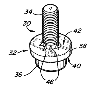
Figure 1 is an isometric view of a first embodiment
of the electrical grounding stud of the present invention.
12 ~~~ri ~~~!~~
Figure 2 is a partial cross sectional view of the
electrical grounding stud of figure 1 and a typical installation
apparatus.
Figure 3 is a partial cross sectional side view of
the electrical grounding stud of Figure 1 shown installed in an
electrically conductive panel.
Figure 4 is a partial cross sectional top view of
the first embodiment of the electrical grounding stud of the
present invention taken substantially along lines 4-4 of Figure
2.
Figure 5 is a cross sectional bottom view of the
first embodiment of the electrical grounding stud of the present
invention taken substantially along lines 5-5 of Figure 3.
Figure 6 is a partial cross sectional view of the
first embodiment of the electrical grounding stud assembly of
the present invention shown installed in a panel the assembly
including a grounding lug and a first embodiment of a protective
lug nut of the present invention.
Figure 7 is a side view of the first embodiment of
the electrical grounding stud of the present invention shown
installed in a panel with a grounding lug and a second
embodiment of the protective lug nut of the present invention.
Figure 8 is an isometric view of a second embodiment
of an electrical grounding stud of the present invention and a
third embodiment of the protective lug nut of the present
invention.
Figure 9 is a top view of the second embodiment of
the electrical grounding stud of the present invention taken
substantially along lines 9-9 of Figure 8.
-13-
Figure 10 is a partial cross sectional side view of
the second embodiment of the electrical grounding stud of the
present invention taken substantially along lines 10-10 of
Figure 9.
Figure 11 is a partial cross sectional view of a
typical installation apparatus used to install the second
embodiment of the electrical grounding stud of the present
invention into an electrically conductive panel.
Figure 12 is a cross sectional bottom view of the
second embodiment of the electrical grounding stud of the
present invention and the installation plunger of a typical
installation apparatus taken substantially along lines 12-12 of
Figure 11.
Figure 13 is a partial cross sectional view of the
second embodiment of the electrical grounding stud of the
present invention installed in an electrically conductive panel.
Figure 14 3a an isometric top view of the second
embodiment of the electrical grounding stud of the present
invention installed in an electrically conductive panel.
Figure 15 is an isometric view of a third embodiment
of the electrical grounding stud of the present invention.
Figure 1b is a partial cross sectional side view of
the third embodiment of the electrical grounding stud of the
present invention shown in Figure 15.
Figure 17 is a bottom view of the third embodiment
of the electrical grounding stud of the present invention.
-14-
Figure 18 is a bottom view of a fourth embodiment of
an electrical grounding stud of the present invention.
Figure 19 is a fifth embodiment of an electrical
grounding stud of the present invention.
Figure 20 is a partial cross sectional side view of
a sixth embodiment of the electrical grounding stud of the
present invention shown assembled to a third embodiment of a
protective nut.
Figure 21 is a partial cross sectional side view of
the electrical grounding stud of Figure 20 assembled to a fourth
embodiment of a protective nut of the present invention.
pETAII.ED DESGltIPTIOPI OF THE PREF&RHED EriBOD~TS
The electrical grounding connector and grounding
connector assembly of the present invention is particularly
adapted for permanent attachment to a panel or plate,
particularly a metal sheet or the like, such as utilized in the
automotive and appliance industries. The disclosed electrical
grounding connector and assembly is particularly well suited for
installation by Way of conventional press apparatus typical of
that utilized in the automotive industry. The method of the
present invention is also well suited for application by way of
conventional press. In such applications, the press installs
one or more connector assemblies with each stroke wherein the
connector assemblies become a permanent part of the panel and
are utilized to affix other members such as brackets or the like
to the panel. Further, the electrical grounding connector of
the present invention is particularly suited for attachment to
relatively thin sheets or panels, such as utilized by the
appliance industries. Accordingly, as used herein, '°panel°'
refers to any plate, panel, or metal sheet having sufficiently
CA 02073744 2002-03-27
-15-
low electrical conductivity to be considered an effective
electrical conductor and a thickness sufficiently thin for
practical application of the riveting portion of the
grounding connector.
Now referring to Figure 1, in a first embodiment, the
electrical grounding stud (or connector) 30 of the present
invention includes body portion 32 disposed between, and
integrally joining, stud portion 34 and riveting portion
36. Body portion 32 includes flange 38 which extends
generally radially from body portion 32 and includes panel
engaging surface 40 and lug engaging surface 42.
Now referring to Figures 1 and 2, first barbed
elements 44 are disposed on at least panel engaging surface
40 or riveting portion 36 of grounding stud 30 and
preferably first barbed elements 44 are integral to, and
spanned between, panel engaging surface 40 and riveting
portion 36. Second barbed elements 46 are disposed on at
least stud portion 34 or lug engaging surface 42 and are
preferably integral with and span between stud portion 34
and lug engaging surface 42.
As disclosed in U.S. Patent 4,831,698; 4,555,838; and
4,610,072 (hereinafter '698, '838 and '072 respectively),
electrical grounding stud 30 is adapted to be riveted to
plastically deformable electrically conductive panel 48. As
disclosed in '838 patent, riveting portion 36 of the
grounding stud 30 preferably includes annular wall 50
defining socket 52 within riveting portion 36. As
disclosed in the '838 patent, plunger 54 is adapted to
cooperate with die member 56 to drive riveting portion 36
of grounding stud 30 through electrically conductive panel
48 thereby deforming riveting portion 36 radially outward
forming a secure mechanical interlock between stud 30 and
conductive panel 48.
16
Now referring to Figures 1-3, as plunger 54 drives
riveting portion 36 of grounding stud 30 into electrically
conductive panel 48, first barbed elements 44 eventually
contact, and are driven into, and penetrate, the surface of
panel 48. Tf grounding stud 30 is fashioned without first
barbed elements 44 (such as is the stud disclosed in the '838
patent) any non-conductive substance dispose between grounding
stud 30 and panel 48 increases the electrical resistance between
grounding stud 30 and panel 48 thereby undersirably affecting
the grounding capacity of grounding stud 30 and panel 48. Tn
automotive applications, it is common for paints, rust
preventative coatings, oils, and other non-electrically
conductive (or poor electrically conductive) substances to be
deposited (either intentionally or unintentionally) on surfaces
of a panel 48 which is to have a grounding stud 30 affixed to
it. Because of these materials which reside, or inevitably find
their way between grounding stud 30 and panel 48, the fastener
set out in the '838 patent (which does not utilize first
grounding barbed elements 44) was not effective as an electrical
grounding stud (notwithstanding the highly effective mechanical
bond between grounding stud 30 and panel 48). By adding first
barbed elements 44 to grounding stud 30, any electrically
non--conductive residue disposed between grounding stud 30 and
panel 48 is penetrated through, and displaced, by first barbed
elements 44 during the installation process as first barbed
elements 44 penetrate the surface of electrically conductive
panel 48. This penetrating engagement between barbed elements
44 and panel 48 creates an excellent bridge for electrical
current between the two mating materials. Tn prototypes of the
present invention, it has been demonstrated that when grounding
stud 30 of the present invention is installed on panels which
are coated with electrically non-conductive substances such as
paint, rust preventative coatings and the like, excellent
results are achieved and grounding stud 30 forms an excellent
current path to panel 48.
_ _ " sw
1 ~ ~ r~ el ~ '~ '.~
In an application, as shown in Figure 3, an
electrically conductive grounding lug 58 is connected to an
electrical wire 60 which is to be grounded to panel 48.
Grounding stud 30 of the present invention, once fastened to
electrically conductive panel 48, provides a simple and
inexpensive way of grounding lug 58. If lug 58 is in the form
of a '°eye" lug, the aperture 60 of lug 58 is passed over stud
portion 34 of grounding stud 30 and pressed against lug engaging
surface 42 by a nut (nut not shown in Figure 3) or other similar
means. By exerting sufficient farce upon lug 58, second barbed
elements 46 cut into lug 58 thereby displacing any electrically
non-conductive contaminants which may reside therebetween
ensuring a high integrity electrical connection between lug 58
and grounding stud 30.
As those skilled in the art will readily recognize,
the presence of first and second barbed elements 44, 46
respectively, provide a means of securing an electrical
grounding lug 58 to a panel 48 in a way which provides an
electrical grounding connection of high integrity. Thus, the
lug of the present invention overcomes the problems of the prior
art lugs which serve as superior mechanical connectors to panel
48, but do not provide the electrical resistance characteristics
needed for grounding applications.
Now referring to Figures 1-5, although first and
second barbed elements 44, 46 respectively may be fashioned into
any number of geometries, excellent results have been achieved
using polyhedron type geometries as seen in Figures 1 through
Figures 5. It will be understood by those skilled in the art,
that a primary concern in achieving good electrical conductivity
between lug 58 and grounding stud 30, and grounding stud 30 and
panel 48 is primarily a function of the ability of first and
second barbed elements 44, 46 to "bite into" and penetrate the
CA 02073744 2002-02-21
-18-
surface of lug 58 and panel 4$. Thus, in order to achieve the
lowest possible electrical resistance between interfacing
surfaces, the material composition of lug 58 and panel 48 will
have a direct bearing on the preferred geometry and hardness of
first and second barbed elements 44, 46.
As disclosed in the aforementioned patents, riveting
portion 36 of grounding stud 30 can be used in panels 48 having
prepierced openings. Although this may be desirable in some
installations, riveting portion 36 is also suited to pierce
panel 48 during installation thereby creating its own panel
openings. During this piercing operation, slug 62 is severed
from panel 4$ and can be either discarded through die opening 64
of die member 56 or, in the alternative, can be permanently
staked within socket 52. Various techniques for staking plug 62
within socket 52 are disclosed in U.S. Patent No, 5,174,018.
Now referring to Figures 6 and 7, although many-
different styles of nuts 66, 68 may be used to secure grounding
lug 58 to grounding stud 30, the preferred nut includes one open
end and one closed end (closed end indicated at 70). The open
end functions to provide a passage way for stud portion 34 of
grounding stud 30 to gain entrance into nuts 66, 68 and closed
end 70 prevents paint, undercoating or the like from contacting
the threads of stud portion 34 or various electrically
conductive surfaces of grounding stud 30. Accordingly, nut 66,
58 prevent paint, undercoating or the like from hampering the
electrical integrity between lug 58 and stud 30. Nut 66 differs
from that of nut 68 in that nut 66 has a polygonal outer surface
along the lower half of its structure while nut 68 has a
polygonal surface along the upper half of its structure.
Depending upon the particular application, type of installation
tools used, and the like, one disclosed embodiment may be
desirable over the other. However, each nut 66, 68 functions
-19-
identically to force lug 58 against second barbed elements 46
thereby forming an electrical connection therebetween of high
integrity and, also, functions to keep contaminants and other
undesirable substances from contacting stud portion 34 or lug
58. Although only one lug is disclosed in Figures 6 and 7, it
is to be understood by those skilled in the art that multiple
lugs may be electrically accommodated by a single grounding stud
30 where such a requirement is desirable.
Now referring to Figures 8-10, a second embodiment
of the grounding connector of the present invention includes an
electrical grounding connector assembly 72. The assembly 72
includes a second embodiment of electrical grounding stud 30
(second embodiment indicated at reference numeral 74) and
protective cap 76. The primary difference between electrical
grounding connector assembly 72 and that disclosed in
conjunction with Figures 1-6, is that the assembly 72 is adapted
to be installed, as an assembly, into a panel in a single
installation operation. This will be further described in
reference to Figures 8-14.
Now referring to Figures 8=10, electrical grounding
stud 74 includes body portion 32, stud portion 34, and riveting
portion 36. As disclosed in conjunction with grounding stud 30,
body portion 32 is disposed between, anct integrally joins, stud
portion 34 and riveting portion 36. Body portion 32 includes
flange 38 which extends generally radially from body portion
32. Flange 38 includes panel engaging surface 40 and lug
engaging surface 42. Panel engaging surface 40 of flange 38
includes first barbed elements 44 and pockets 78. Barbed
elements 44 generally rise above panel engaging surface 40 while
pockets 74 generally reside below panel engaging surface 40.
While first barbed elements 44 function identically to that
disclosed in the first embodiment of electrical grounding stud
30 (as discussed in conjunction with Figures 1-7), they also
-20-
provide, in conjunction with pockets 78, superior anti-rotation
resistance upon fastening grounding stud 74 to a panel. The
superior anti-rotation resistance is largely due to the fact
that the combination of elevated barbs 44 and depressed pockets
78 accommadate under-hit and over-hit conditions which are
typically associated with fastener installations techniques
which use presses. As understood by those skilled in the art,
it is impossible to control the precise stroke upon that a press
platen will travel during the course of installing grounding
stud 74 in panel 48. Because of this unpredictability, some
grounding studs 74 will be forced into a mating panel deeper
than preferred (this is commonly known as an over-hit condition)
and alternatively, in some instances, grounding stud 74 will not
be driven into the mating panel to the extent that it should be
(this is commonly termed as an under-hit condition). Grounding
stud 74 of the present invention is particularly well suited to
accommodate under-hit and over-hit conditions in that in the
event of an over-hit condition, panel metal is driven into
pockets 78 thereby giving stud 74 excellent torque resistance
while also providing similar panel penetration features
associated with first barbed elements 44 (as disclosed in
conjunction With Figures 1-7) thereby allowing stud 74 to
function adequately as an electrical grounding stud. On the
other hand, when ground stud 74 experiences an under-hit
condition upon installation (while pockets 78 may experience
little to no panel metal contact) raised barbed elements 44 will
penetrate into the mating panel surface thereby providing torque
resistance and an excellent conductivity interface.
As discussed in conjunction with the grounding stud
disclosed in Figures 1-7, first barbed elements 44 preferably
extend across panel engaging surface ds0 and integrally join
annular wall 50 of riveting portion 36. When first barbed
elements 44 are fashioned in such a manner, cutting edge 80 is
formed at the intersection of panel engaging surface 40 and
. _21_
riveting portion 36 providing a cutting edge which scores the
surface of the mating panel during installation of fastener 74
providing excellent electrical conductivity between stud 74 and
the electrically conductive panel which stud 74 is fastened to.
Lug engaging surface 42 includes surface 82 which is
proximate stud portion 34 and surface 84 which is distal stud
portion 34. Surface 82 is raised relative to surface 84 thereby
creating step surface 86.
Protective cap 76 is adapted to positively engage
stud portion 34 and surface 82 of lug engaging surface 42. Cap
76 is fashioned similar to nuts 66, 68 in that it has only one
open end (which accepts stud portion 34). End 70 is closed
thereby preventing paint, coatings, and the like from contacting
stud portion 34 or surface 82. As will be discussed in
conjunction with Figures 11-14, cap 76 is preferably fastened to
stud portion 34 of grounding stud 74 prior to installing
assembly 72 in an electrically conductive panel. Ey installing
assembly 72 as a single unit into an electrically conductive
panel, the panel can be painted, or otherwise coated before or
after installing assembly 72, without adversely effecting the
grounding characteristics of grounding stud 74. If assembly 72
is installed on an electrically conductive panel after the panel
is painted or otherwise coated, barbed elements 44 and pocket 78
will act, as has already been described, to penetrate any
coatings on panel 48 to provide an ample grounding path between
stud 74 and panel 48. If assembly 72 is sub jected to paint or
other contaminants once it is installed in an electrically
conductive panel, protective cap 76 will prevent stud portion 34
or surface 82 from being contacted by any contaminants. When it
is appropriate to attach a grounding lug to stud portion 34,
protective cap 76 is simply removed and discarded and a lug is
placed around stud portion 34 (as has already been described)
and secured thereto by a nut or other suitable means. In view
-22-
of the above, it is easily understood, that the second
embodiment of the grounding connector of the present invention
is well suited for achieving good electrical conductivity
between itself and a mating panel while also providing excellent
torque. resistance regardless of under-hit or over-hit
installation conditions.
Now referring to Figures 11-14, in the preferred
method of installing assembly 72, assembly 72 is placed adjacent
panel 48 (see Figure 11) such that riveting portion 36 of
electrical grounding stud 34 is proximate panel 48. As
discussed in conjunction with Figure 2, plunger 54 is attached
to the platen of a press or the like which is adapted to develop
sufficient force to pierce panel 48 with riveting portion 36 of
electrical grounding stud 74. Surface 84 of flange 38 acts as a
plunger engaging surface enabling the downward forces exerted by
plunger S4 against electrical grounding stud 74 to be directly
transferred to grounding stud 74 (and do not pass througki cap
76). It would be impractical to transmit the downward force of
plungex 54 through cap 76 inasmuch as the preferred materials
for cap 75 are plastic and the like. Although plastic or the
like is the preferred material (because protective cap 76 is
typically discarded at the time an electrically conductive lug
is placed on stud portion 34), any other inexpensive, readily
removable, substitute may be used such as rubber, various
coatings, and the like.
As seen in Figure 13, cutting edge 80 forms an
excellent electrical interface between electrical grounding stud
74 and electrically conductive panel 48 while the combination of
barbed elements 44 and pocket 78 form excellent anti-rotation
means accommodating both over-hit and under-hit conditions. As
previously explained in conjunction with Figure 3, electrical
grounding stud 74 is suited for use both in prepierced panel
applications and non-prepierced panel application. When
-23-
electrical grounding stud 74 is used in non-prepierced panel
applications, slug 52, which is severed from panel 48 during
installation, can either be discarded or permanently staked
within socket 52.
Now referring to Figures 15-19, although many
different geometries may be used to accomplish superior
electrical interface between electrical grounding stud 74 and an
electrically conductive panel, the specific location and
geometry of cutting surfaces disposed on electrical ground stud
74 are believed to be important. For example, in the
alternative embodiments of electrical grounding stud 74 set out
in Figures 15-17, flange 38 is generally polygonal (see Figure
17) having arcuate, coved splines 88 superimposed thereon.
Splines 88 intersect panel engaging surface 40 and lug engaging
surface 42 thereby creating vertices 90 which form excellent
cutting geometries to penetrate panel 48 thereby creating
excellent electrical conductivity from electrical grounding stud
74 to mating panel 48. Other embodiments of flange 38 include
designing flange 38 with an outer surface resembling that of a
hypocycloid preferably having eight cusps 92 (see Figure 18).
In the embodiment of grounding stud 74 set out in Figure 18,
cusps 92 function similarly to that of vertices 90.
Still, in an alternative embodiment, Figure 19 shows
flange 38 being generally poloygonal having a plurality of
arcuate raised surfaces 94 superimposed thereon. It is fully
contemplated that geometries other than those shown in Figures
3, 9, and 15-19 are also suitable for providing excellent
electrical conductivity between assemblies using electrical
grounding stud 74 and mating panel 48.
Now referring to Figure 20, in a preferred
embodiment, protective nut 96 also functions as a means for
translating the downward force of plunger 54 to the electrical
24 ~~~ a~~
grounding stud during the installation process. As can be seen
from figure 20, unlike the embodiment of nut 76 set out in
Figure 8, if nut 96 is comprised of metal or the like, it can be
designed with sufficient strength to withstand the downward
force exerted against 3t by plunger 54 during the installation
process. By designing nut 96 from metal, or other similar
materials, several advantages are gained. firstly, the radius
of flange 38 can be reduced (over that disclosed in conjunction
with the embodiment of electrical grounding stud shown in
Figures 8-14). This is possible because plunger engaging
surface 84 is not needed and therefore can be eliminated. This,
of course, results directly in a cost saving due to reduced
materials and also results in a weight reduction per unit
electrical grounding stud. As can be seen from figure 20,
plunger 54 acts directly against external surface 71 of closed
end 70 of nut 96. The force is translated through nut 96
causing electrical grounding stud 74 to pierce through panel 48
in the manner which has already been discussed. In order to
ensure positive engagement between plunger 54 and external
surface 71, plunger 54 is designed having gap 100.
In an alternative approach, plunger 54 is adapted to
bear upon engaging surface 84 of nut 96 thereby transferring a
downward force against electrical grounding stud 74 through lug
engaging surface 42. In order to ensure positive contact
between plunger 54 and engaging surface 84, plunger 54 is
designed having gap 100.
In addition to the reduction in weight and cost
associated with eliminating plunger engaging surface 84 from
flange 38, an additional benefit is realized when nut 96 is
constructed from metal. This additional benefit arises because
nut 96 can, in addition to providing the protective function
which has already been discussed in conjunction with protective
cap 76, be used as the means for securing an electrical
-25- ~ a~ ~ F ~ r
grounding lug to lug engaging surface 42 of electrical grounding
stud 7G. Far example, once electrical grounding stud 74 is
fastened to electrically conductive panel 48, metal nut 96 is
unthreaded (or otherwise removed) from stud portion 34 and an
electrical grounding lug is placed against lug engaging surface
42 of electrical grounding stud 74. Then, metal nut 96 is drawn
against the electrical lug such that a secure electrical contact
is made between the grounding lug and lug engaging surface 42.
This approach has the obvious advantage over constructing the
nut from plastic in that the plastic nuts are simply disposed of
after they provide their protective function and must be
replaced by a metal nut to perform the function of securing a
grounding lug to the electrical grounding stud. In a high
production setting, the discarded plastic nuts must be collected
and disposed of in an orderly fashion in order to eliminate
potential safety hazards and other problems associated with
improperly discarded nuts. The metal nut disclosed in Figures
20 and 21 eliminates this problem inasmuch as the metal nut
services to both protect stud portion 34 from contaminants while
also serving the utilitarian function of securing an electrical
grounding lug against lug engaging surface' 42 of electrical
grounding stud 74.
Having described .the preferred embodiment of the
grounding connector, grounding connector assembly, and the
preferred methods of attaching the grounding connector and
grounding connector assembly Lo an electrically conductive
panel, it will be understood that various modifications or
additions may be made to the preferred embodiments chosen here
to illustrate the present invention, without departing from the
spirit of the present invention. For example, the relative
dimensions of the grounding connectors and associated nuts
herein disclosed will depend largely upon the particular
application at hand and the selected panel thicknesses. As has
been herein described, the grounding connector and grounding
-26-
connector assembly is particularly suited for attachment to
electrically conductive panels such as utilized for body and
structural components in the automotive and appliance
industries. As will be understood by those skilled in the art,
the connector assembly of the present invention is preferably
formed of plastically deformable metal, preferably steel, which
may be heat treated for surface hardness, ductility, and other
desirable features. A suitable material for the fasteners
herein disclosed is medium carbon steel suitable for cold
forming, including SAE 1022, 1023, and 1030 steels. Excellent
results have been achieved with steels in the range of SAE 1020
through SAE 1040. Reference also may be made to the earlier
cited patents far further information regarding suitable
installation, apparatus, self-piercing and riveting fasteners
and methods of installing same. Accordingly, it is typically
understood that the subject matter sought to be afforded
protection hereby shall be deemed to extend to the subject
matter defined in the appended claims, including all fair
equivalents thereof.