Note: Descriptions are shown in the official language in which they were submitted.
2073840
Method of Welding Nickel
or Nickel Alloy Products
Background of the Invention
Field of the Invention
This invention relates to welding methods for nickel or
nickel alloy products having excellent corrosion resistance
and high-temperature strength, clad metals covered with a
layer of nickel or a nickel alloy, and double pipes with a
mechanically joined inner pipe of nickel or a nickel alloy,
and more particularly to gas tungsten arc welding methods
therefor.
Description of the Prior Art
Recently the number of natural gas and oil wells
exploited in highly corrosive environments and chemical
plant pipelines used for the transportation of highly
corrosive fluids has been increasing sharply.
Conventional carbon steel pipes, even if corrosion
resistance is improved by the addition of special alloying
elements or by special heat treatments or even if corrosion
inhibitors are added to corrosive fluids they conduct,
cannot prevent corrosion from inside. Besides, they do not
have high enough strength to withstand the increasing
pressure involved in the transportation of fluids.
This is the reason why products of nickel or a nickel
alloy (alloys containing more than approximately 15 % each
of chromium and nickel), clad metals overlain with a layer
20738~0
. .
of nickel or a nickel alloy and double pipes with an inner
pipe of nickel or a nickel alloy have found extensive use.
Gas tungsten arc welding having the following advantages is
commonly used with these pipes.
(1) Welding with low rates of gas dilution does not
heavily impair the corrosion resistance of welded joints.
(2) Few weld defects occur when welding is performed
under appropriate conditions.
(3) Beautiful and smooth appearance can be obtained,
without requiring slag removal or bead grinding during
welding.
High-nickel or high-molybdenum welding materials having
higher corrosion resistance and high-temperature strength
than the base metal (the inner pipe or cladding metal in the
case of a double pipe) are used. For example, Inconel 625
or Hastelloy 276 (trademarks for corrosion-resistant
nickel-base alloys) alloy is commonly chosen.
Conventional gas tungsten arc welding is so inefficient
and time-consuming that construction of long pipelines has
been very costly. Though recently developed high-strength
clad steel pipes overlain with Incoloy 825 (a trademark for
corrosion-resistant alloys) or Inconel 625 or reinforced
with a mechanically joined inner pipe has realized a
substantial cutback in material cost, the high construction
cost mentioned above has prevented the expansion of their
use.
Welding of nickel-rich alloys or high-strength clad
2073840
metals overlain with such alloys with high-nickel filler
metals such as Inconel 625 or Hastelloy 276 by the
conventional gas tungsten arc process basically differs from
that of carbon steel in the following two points.
When molten, to begin with, the alloys are more viscous
and less fluid, and, therefore, does not wet the sides of
the groove as much as carbon steel. Wetting of the groove
sides by the molten metal is very important welding
performed in all positions, as in the on-site welding of
pipelines. The interfacial tension built up by the wetting
between the base metal and deposited metal supports the
weight of the molten metal, thereby permitting continuous
welding without causing burn-through.
While carbon steel pipes can be welded with high
deposition rate, high-nickel alloy pipes must be welded with
low deposition rate. This is the reason for the
low-efficiency welding mentioned before.
The poor wetting has conventionally been improved by
simultaneously causing the arc torch and filler wire to
oscillate through the groove. This conventional method is
designed to promote the groove sides by the deposited metal
by oscillation, placing an appropriate amount of deposited
metal at the most suitable point in the groove, which is, to
be more specific, near the side walls thereof, and thus
prevent burn-through.
Still, this oscillating method too has its limit. When
the stroke of oscillation is increased, the welding speed in
20738~0
. .
the middle of the groove becomes so high that insufficient
heat input and filler wire sticking tend to occur to impair
the quality of welding.
Secondly, the depth of penetration resulting from the
arc welding of high-nickel alloys is smaller than that with
carbon steel. Therefore, the groove in the weld zone (the
height of the root face) must be reduced to between
approximately 1.0 and 1.4 mm, whereas the butt weld must be
made with extremely high accuracy. This is another reason
for the low construction efficiency.
Filling these gaps with carbon steel is the key point
in the improvement of the welding technology for products of
nickel or a nickel alloy, clad metals covered with a layer
of nickel or a nickel alloy, and double pipes with a
mechanically joined inner pipe of nickel or a nickel-alloy.
Various improving attempts have been made with the
convention gas tungsten arc welding method. For example,
the welding current was increased beyond the tolerable limit
to increase the wetting by the deposited metal and the
oscillating speed was lowered to obtain deeper penetration.
However, these attempts have not brought about any major
improvement in welding efficiency, often entailing, instead,
various welding defects.
Summary of the Invention
The object of this invention is to solve the
conventional technical problems described above by providing
efficient defect-free gas tungsten arc welding methods for
20738~0
nickel or a nickel alloy products.
A gas tungsten arc welding method of this invention
comprises the steps of generating an arc between the work
serving as the anode and a tungsten electrode on a welding
torch serving as the cathode, emitting a jet of shielding
gas which comprises an argon-based gas mixture containing
one or both of hydrogen and helium from a confining gas
nozzle having a guide wall concentric with the tungsten
electrode, confining the apparent flaring angle of the arc
to within 80 degrees, and moving the welding torch along the
weld line while feeding the tip of the filler wire into a
molten pool formed directly below the arc.
Another gas tungsten arc welding method of this
invention comprises the steps of generating an arc between
the work serving as the anode and a tungsten electrode on a
welding torch serving as the cathode, emitting a jet of
shielding gas from a confining gas nozzle concentric with
the tungsten electrode, causing a first filler wire to
oscillate together with the welding torch with a
predetermined amplitude and cycle in a direction
perpendicular to the weld line and moving the same along the
weld line while feeding the tip of the first filler wire
into a part of a molten pool formed directly below the arc,
and causing a second filler wire to oscillate in synchronism
with the motion of the first filler wire and moving the same
along the weld line while feeding the tip of the second
filler wire into the molten pool at a point 180 degrees away
20738~0
.,
from the oscillating phase of the first filler wire.
The shielding gas used in this invention is an argon-
based gas mixture containing one or both of hydrogen and
helium.
The welding methods of this invention remarkably
elevates the temperature of the molten pool directly below
the arc by increasing the energy of the arc by supplying the
shielding gas, which comprises a mixture of argon with one
or both of hydrogen and helium, to the welding torch having
a confining gas nozzle and concentrating the distribution of
the arc at the anode. This improvement readily enhance the
penetration in the first (root) pass, in particular, with
the resulting welding efficiency being three to four times
higher than that of the conventional gas tungsten arc
welding.
The oscillation of two filler wires in the groove is
effective on the second and other subsequent passes. The
resulting higher molten pool temperature permits increasing
the feed rate and oscillation amplitude of the first filler
wire, which, in turn, realizes welding with high deposition
rate. The increased wetting and the cooling effect of the
second filler wire, in combination, prevents the dropping of
the molten metal and assures the forming of defect-free
welds of satisfactory quality.
This invention is applicable to the welding of pipes,
sheets, plates and various structural shapes of metals, with
at least one of the pipes, sheets, plates and structures
20738~0
being made of nickel or a nickel alloy. This invention
further expands the use of various forms of nickel or nickel
alloy products including clad metals overlain with nickel or
a nickel alloy and double pipes having a mechanically joined
inner pipe of nickel or a nickel alloy.
Brief Description of the Drawings
FIG. 1 shows a mechanically joined corrosion-resistant
double pipe made by applying a welding method of this
invention. FIG. 1 (a) is a cross-sectional view of the
double pipe. FIG. 1 (b) is a cross-sectional view of a
seal-welded end of the same pipe. FIG. 1 (c) is a detail
view of a groove between two double pipes joined together by
butt welding.
FIG. 2 is a vertical cross-sectional view of a welding
torch used in a welding method of this invention.
FIGs. 3 (a) and (b) are perspective views showing the
relative position of a first and a second filler wire
oscillating in a welding method of this invention.
FIG. 4 diagrammatically shows how the conditions of an
automatic gas tungsten arc welding method according to this
invention are controlled. The controlled welding conditions
include the welding speed, oscillation of the welding torch
and first filler wire, pulse of the arc, feed rate of the
first filler wire, and oscillation and feed rate of the
second filler wire.
FIG. 5 is a schematic plan view of a welding apparatus
for implementing a welding method according to this
20738~0
...
invention.
FIG. 6 is a cross-sectional view showing the profile of
a groove between two corrosion-resistant double pipes joined
together by a welding method of this invention, and the
dimensional tolerance of the groove and butt weld.
FIG. 7 (a) is a macroscopic photograph of a weld joint
made by a welding method according to this invention. FIG.
7 (b) is a macroscopic photograph of a weld joint made by a
conventional automatic gas tungsten arc welding method.
Description of the Preferred Embodiments
A preferred embodiment of this invention will be
described by reference to FIG. 1 that shows an example of
all-position welding applied to a mechanically joined
corrosion-resistant double pipe.
FIG. 1 shows a cross-section of a mechanically joined
corrosion-resistant double pipe made by a welding method
according to this invention.
A corrosion-resistant double pipe 1 shown in FIG. 1 (a)
consists of a corrosion-resistant inner pipe 2 containing a
high percentage of nickel and an outer pipe 3 of high-
strength, high-toughness carbon steel. The two pipes are
mechanically joined or otherwise put together by either
expanding the inner pipe or heating and shrink fitting the
outer pipe.
Both ends of the corrosion-resistant double pipe 1
should preferably be seal-welded by forming an overlay 5 by
automatic gas tungsten arc welding with a filler wire
20738~0
containing much more nickel or molybdenum than the inner
pipe 2, as shown in FIG. 1 (b).
Then, two corrosion-resistant double pipes 1 are butt-
welded. As shown in FIG. 1 (c), a groove for butt welding
is formed between the two pipes according to the
predetermined groove angle (e. g., 22.5 degrees), root face
thickness (e. g., 1.6 mm), nose length (e. g., 2.8 mm) and
root radius (e. g., 1.2 mm R).
The nickel or molybdenum content of the overlain weld 5
thus formed should preferably be higher than that of the
inner pipe 2 and substantially equal to that of the welding
material so that the resulting condition is similar to the
one obtained when a pipe of such composition is welded
thereto.
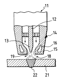
Referring now to FIG. 2, an automatic gas tungsten arc
welding torch used in a welding method of this invention
will be described.
A welding torch 11 has a tungsten electrode 12
connected to the negative pole of a power supply (not
shown). An arc 18 is formed between the tungsten electrode
12 and the base metal 21, with a molten pool 22 of metal
formed directly below the arc. The welding torch 11 also
has a confining gas nozzle 14 concentric with the tungsten
electrode 12. The tip 15 of the confining gas nozzle 14 is
constricted so that the apparent or visible flaring angle of
the arc should not exceed 80 degrees. The tip 13 of the
tungsten electrode 12 is positioned at the tip 15 of the
20738~0
nozzle. A cooling water passage 16 is provided at the tip
15 of the confining gas nozzle 14. The cooling water
flowing through the passage 16 keeps the inner wall of the
confining gas nozzle 14 below, for example, 40 C during
welding. A shielding gas 19 supplied to the confining gas
nozzle 14 is emitted from an opening between the nozzle tip
15 and the tip 13 of the tungsten electrode.
The welding torch 11 with the confining gas nozzle 14
just described is of a common type usually used for keyhole
plasma-arc welding. However, the pressure or flow rate of
the shielding gas for the keyhole welding is too much for
the welding method of this invention. The flow rate
employed in general gas tungsten arc welding is appropriate.
To be more specific, the appropriate flow rate of the
shielding gas 19 is 3 to 8 liters per minute. Within this
range, the arc 18 does not become parallel-sided like a
plasma arc and no keyhole is formed in the molten pool 22.
The use of the welding torch 11 with the confining gas
nozzle 14 in the way just described and an argon-based
shielding gas 19 mixed with one or both of hydrogen and
helium that induce ionization or dissociation increases the
energy of the arc column, accelerates the concentration of
anode distribution, and remarkably elevates the temperature
of a part of the molten pool 22 directly below the arc.
This gas, together with the design of the confining gas
nozzle, readily confines the apparent flaring angle of the
gas tungsten arc within 80 degrees.
- 10 -
20738~0
,.
The mixed gases (argon plus hydrogen, argon plus
helium, or argon plus hydrogen and helium) produce
remarkable effects.
The mixed gases of the following three compositions are
recommendable.
(1) A mixed gas consisting of 95 to 98 % of
lndustrially pure argon and 2 to 5 % of industrially pure
hydrogen.
(2) A mixed gas consisting of 40 to 50 % of
lndustrlally pure argon and 50 to 60 % of lndustrlally pure
helium.
(3) A mixed gas consisting of 45 to 55 % of
industrially pure argon, 40 to 50 % of industrially pure
helium, and 2 to 5 % of industrlally pure hydrogen.
When two filler wlres osclllate in the groove, the
molten pool directly below the arc is heated to such a high
temperature as to permit the first filler wire to be
continuously inserted therein. This greatly lncreases the
meltlng speed of the flrst flller wire and widens the
difference in temperature and surface tenslon between the
peripheral and central parts of the molten pool. The
widened difference in surface tension strengthens the
surface stream of the molten metal supplied from the first
filler wire, contributing greatly to the enhancement of
wetting mentioned before.
Referring to FIGs. 3 and 4, a method of oscillating a
first filler wire (hereinafter called the main filler wire)
20738~0
and a second filler wire (hereinafter called the auxiliary
filler wire) according to this invention will be described
below.
The welding torch 11 and a main filler nozzle 25
according to this invention oscillate with a predetermined
amplitude and cycle in a groove 23 in a direction
perpendicular to the weld line, as shown in FIGs. 3 (a) and
(b). In FIG. 3 (a), the welding torch 11 and main filler
nozzle 25 oscillate to the right wall 23a and dwell there
for a given time. Continuous welding is performed in this
state, with a converged arc 18 generated at the tip 13 of
the tungsten electrode 12 in the welding torch 11, a molten
pool 22 formed thereunder, and the main filler wire 26 fed
from the main filler nozzle 25 into the molten pool 22
directly below the arc.
An auxiliary filler nozzle 28 feeds the auxiliary
filler wire 29 to the backward part of the molten pool 22
from the opposite side of the main filler wire 26 coaxial
with the oscillating direction. The relative position of
the main filler wire 26 and auxiliary filler wire 29 is
controlled so that the auxiliary filler wire 29 oscillates
in synchronism with the welding torch 11 and main filler
wire 26, as shown in FIG. 3 (b) in which the main filler
wire 26 oscillates to the left wall 23b.
FIG. 4 shows how the welding speed of the torch
carriage, oscillation of the welding torch 11 and main
filler wire 26, current and voltage pulses of the arc 18,
- 12 -
20738~0
feed rate of the main filler wire 26, and oscillation and
feed rate of the auxiliary filler wire 29 are controlled.
For example, low current and voltage pulses are
selected so that the peak and base periods thereof can be
freely set between 0.5 and 3 Hz. In FIG. 4, the peak period
is identical with a period during which the welding torch 11
and main filler wire 26 dwell at the left wall 23b of the
groove, whereas the base period is identical with a period
during which the welding torch 11 and main filler wire 26
passes the middle part of the groove 23. The feed rate of
the main filler wire 26 and auxiliary filler wire 29 is also
pulse-controlled, with the peak and base feed rates of each
filler wire being synchronized with the peak and base
periods of the arc 18.
The feed rate of the main filler wire 26 and auxiliary
filler wire 29 should preferably be set so that the metal
from the main filler wire 26 accounts for 80 % to 90 % of
the deposited metal and the metal from the auxiliary filler
wire 29 accounts for 10 % to 20 % thereof. As is obvious
from FIG. 4, the auxiliary filler wire 29 is fed to cool the
peripheral part at the back of the molten pool 22 by
liberating the latent heat therefrom. This further
increases the surface tension of the sufficiently wet molten
metal between the side walls 23a and 23b of the groove 23.
The deposited metal from the main filler wire 26 prevents
the drop of molten metal when all-position welding is
performed in the downward and upward positions, thus
20738~0
permitting an all-position welding with a higher deposition
efficiency than before.
FIG. 5 schematically shows an automatic welding
apparatus to implement the welding method of this invention.
A carriage 31 driven by a travelling motor 32 runs in
the direction of arrow A over rails 33 laid along the weld
line at a desired welding speed. To the forward end of an
oscillation frame 34 mounted on the carriage 31 are attached
the welding torch 11 and main filler nozzle 25. A main
oscillation unit 35 is connected to the oscillation frame
34. The main oscillation unit 35, which comprises a crank
and cam mechanism and an oscillation motor 36 to drive the
crank and cam mechanism, causes the oscillation frame 34 to
oscillate. As a consequence, the welding torch 11 and main
filler nozzle 25 oscillate integrally in direction B that is
perpendicular to the weld line. Near the forward end of the
oscillation frame 34 is provided an auxiliary oscillation
unit 42 which comprises a cam mechanism and an oscillation
motor 43 to drive the same. The auxiliary filler nozzle 28
connected to the auxiliary oscillation unit 42 oscillates in
direction C that is perpendicular to the weld line. A pair
of pinch rolls 38 driven by a feed motor 49 feeds the
auxiliary filler wire 29 through a feed liner 45 to the
auxiliary filler nozzle 28.
A control unit 51 controls the travelling motor 32,
oscillation motors 36 and 43, and feed motors 40 and 49
connected thereto to realize an oscillation pattern shown in
207~8~0
FIG. 4. The control unit 51 is an ordinary computer control
unit having a sequence control function. A main filler
amplitude detector 52 and an auxiliary filler amplitude
detector 53 detect the oscillation patterns of the main
filler wire 26 and auxiliary filler wire 29 and input the
detected patterns into the control unit 51. The control
unit 51 feeds back the oscillation patterns for further
control.
[Example]
The following is a specific example of field welding
performed with corrosion-resistant double pipes of the type
shown in FIG. 1.
Specifications of corrosion-resistant double pipes
(1) Dimensions
Outside diameter: 145.6 mm
Wall thickness:
Outer pipe: 15.8 mm
Inner pipe: 3.0 mm
(2) Material
Outer pipe: API 5L, X70
Inner pipe: Incoloy 825 (UNSN08825)
(3) Overlay welding at pipe end
o Automatic gas tungsten arc welding
o Welding position: pipe rotation lG
o Welding material: Inconel 625 filler wire
Table 1 and FIG. 6 show the profile and dimensions of
the groove between the welded pipes and the dimensional
- 15 -
2073840
-
tolerance of the groove and butt weld.
T a b l e
Dimensional Tolerance of Groove Dimensional Tolerance of Butt Weld
Groove Angle 22.5 + 5 Offset + 0.8mm
Height of Root Face 1.6 + 0.3mm
Nose Length 2.8 + 0.4mm
Root Gap 0 ~ 0.5mm
Root Radius 1.2 ~ 1.4R
Tables 2 and 3 show the welding conditions and required
arc time of the all-position welding according to this
invention and the conventional automatic gas tungsten arc
welding, respectively. FIGs. 7 (a) is a macroscopic
photograph of a weld joint made by a welding method
according to this invention. FIG. 7 (b) is a macroscopic
photograph of a weld joint made by a conventional automatic
gas tungsten arc welding method.
T a b 1 e 2
Pulse Arc Heat Input Torch Oscillation Condition Filler Netal Feed Rate
Type of Torch Pass Current Voltage Travel Am- Perating time (cm/min) Arc
and No. Speed P (sec) Xain Auxiliary Time
Shielding Gas (Amp) (Volt) (%) tude Left Xid- Right Filler Filler
Peak Base Yean Peak Base Peak Base (cm/min) (mm) Wall dle Wall Peak Base Peak Base (min)
Confining 1 110 40 68 11.3 - 40 60 13.2 - - - - - 152 - - 3.1
Gas Nozzle 2 160 70 120 11.410.4 57 43 9.8 3.8 0.4 0.3 0.4 355 254 50 25 4.3
Xixture of 3 180 80 130 12.011.6 50 50 9.8 4.6 0.4 0.3 0.4 406 304 89 38 4.4
96.5% Ar and 4 220 120 170 12.411.8 50 50 7.9 6.1 0.4 0.4 0.4 457 457 81 50 5.4
3.5% H2 5 220 120 175 12.411.8 55 45 7.9 8.9 0.5 0.4 0.5 482 482 81 50 5.4
6 220 140 180 12.411.8 50 50 6.6 13.9 0.5 0.5 0.5 482 482 - - 6.5
Total 29.4 min
C~O
o
T a b 1 e 3
Pulse Arc Heat Input Torch Oscillation Condition Filler
Type of Torch Pass Current Voltage Pulse Travel Am- perating time Metal Arc
and No Ratio Speed P (sec) Feed Rate Time
Shielding Gas (Amp) (Volt) (%) tude Left Mid- Right (cm/min)
Peak Base Mean Peak Base Peak Base (cm/min) (mm) Wall dle Wall Peak Base (min)
1 125 55 83 9.4 - 40 60 7.3 - - - - - 89 5.6
2 160 50 105 9.2 7.2 50 50 7.3 3.5 0.3 0.3 0.3 89 64 5.6
3 180 80 137 9.2 7.4 57 43 7.3 4.0 0.4 0.3 0.4 114 89 5.6
Conventional 4 180 80 137 9.2 7.4 57 43 7.3 4.3 0.4 0.3 0.4 114 89 5.6
GTAW Torch 5 180 80 130 9.2 7.4 50 50 7.3 5.1 0.4 0.4 0.4 114 89 5.6
6 180 80 130 9.2 7.4 50 50 6.5 6.8 0.4 0.4 0.4 140 114 6.1
7-1 180 80 130 9.2 7.4 50 50 6.5 3.5 0.4 0.3 0.2 114 89 6.1
Pure Argon 7-2 180 80 130 9.2 7.4 50 50 6.5 3.5 0.2 0.3 0.4 114 89 6.1
Gas 8-1 180 80 130 9.2 7.4 50 50 6.5 4.3 0.4 0.3 0.2 114 89 6.1
8-2 180 80 130 9.2 7.4 50 50 6.5 4.3 0.2 0.3 0.4 114 89 6.1
9-1 180 80 130 9.2 7.4 50 50 6.5 4.8 0.4 0.3 0.2 114 89 6.1
9-2 180 80 130 9.2 7.4 50 50 6.5 4.8 0.2 0.3 0.4 114 89 6.1
10-1 180 80 137 9.2 7.4 57 43 6.5 5.6 0.4 0.3 0.4 114 89 6.1
10-2 180 80 137 9.2 7.4 57 43 6.5 5.6 0.4 0.3 0.4 114 76 6.1
11-1 180 80 137 9.2 7.4 57 43 6.5 5.8 0.4 0.3 0.4 76 76 6.1
11-2 180 80 137 9.2 7.4 57 43 6.5 5.8 0.4 0.3 0.4 76 76 6.1
Total 95.1 min
2073840
As is obvious from Tables 2 and 3, the welding method
of this invention required an arc time of 29.4 minutes,
against 95.1 minutes required by the conventional automatic
arc welding method. The efficiency of the welding method
according to this invention was approximately three times
greater than that of the conventional gas tungsten arc
welding method.
As can be seen from the photographs of macrostructures
shown in FIGs. 7 (a) and (b), welding by the method of this
invention can be accomplished in six passes, and it permits
oscillation with great amplitude between the second and
final passes. By contrast, the conventional gas tungsten
arc welding method requires sixteen passes and, in addition,
bead parting to prevent sticking, as shown in FIG. 7 (b).
Table 4 shows examples of welding made by methods
combining the confining gas nozzle and shielding gas
according to this invention, while Table 5 shows examples of
welding made by methods combining the confining gas nozzle
and filler metal according to this invention.
- 19 -
20738~0
¢ ~ , ~ ~ ~ ~ CD ~r CD
Y ~ ~ ~ o o ,~ ~ ~ U~
~ , o o ~ ~ ~ ~ o
., ., .~C~ ooooooo
~ Iooooooo
o o o o o o o
~ E ~ s E Ic~~rco ~ ~i ~ oo
O ¢ ~L ~ --'
S --I
~, O ~ E
oc~c~ o o o c~ c~
,0
C~ ~
or-- r-- o o o r- 1--
~ a~ ~ o o o o oo oo
+~ ~ ~
a~ ~ O
O '~
¢
~ ~ ~ o o o o o o o o
~ ¢
C~
~oooooooo
~q. ~ C`J
z ~ ~ ~ ~ ~ CD r-- r-
S c~
L c~ ~ ~H m
o ~ ~ ae
o
'~ ~ --' Z ~ ¢ ~e c~
x ~ .
o C~
- 20 -
T a b l e 5
Pulse Arc Heat Input Torch Oscillation Condition Filler ~etal Feed Rate
Type of Torch Pass Current Voltage Pulse Travel Am- Operating time (cm/min) Arc
and No. Ratio Speed pli (sec) Yain Auxiliary Time
Shielding Gas (Amp) (Volt) (%) tude Left ~id- Right Filler Filler
Peak Base ~ean Peak Base Peak Base (cm/min) (mm) Wall dle Wall Peak Base Peak Base (min)
I 1 120 40 72 10.3 - 40 60 13.3 - - - - - 111 - - 3.1
N Confining 2 140 60 106 10.4 9.6 57 43 9.9 3.5 0.4 0.3 0.4 250 170 40 20 4.3
Gas Nozzle 3 180 70 133 10.4 9.6 57 43 9. 8 4.5 0.4 0.3 0.4 380 270 50 25 4.4
4 220 130 175 10.6 9. 8 50 50 9.6 6.6 0.4 0.4 0.4 380 380 50 30 4.5
Pure Argon 5 220 130 175 10.6 9. 8 50 50 9.6 9.6 0. 4 0.4 0.4 380 380 50 30 4.5
Gas 6 220 130 175 10.6 9. 8 50 50 8.0 11.4 0.5 0.5 0.5 380 380 50 30 5.2
7 220 140 180 10. 6 9. 8 50 50 8.0 13.0 0. 5 0.5 0.5 390 390 60 40 5. 3
Total 31.3 min
oS~
o
20738 10
It has been confirmed that a mixture of argon and
helium and a mixture of argon and hydrogen produce
substantially equal effects as the shielding gas.