Note: Descriptions are shown in the official language in which they were submitted.
07~17'~
1 SPECIFICATION
MAXIMUM-LIK:ELIHOOD DECODING
METHOD AND DEVICE
FIELD OF THE INVENTION
The present invention relates to
maximum-likelihood decoding method and device for
conducting maximum-likelihood decoding on an input
signal subject to intersymbol interference.
Demand for larger capacity recording
precipitates a hi~her density recording in a magnetic
disk apparatus, for example. Accordingly, because
read-out signals are subject to intersymbol interference
to a great extent, making the task of waveform
equalization difficult to achieve (to force equalization
in such a case induces a greater high-band noise), a
high error rate is observed in a decoding operation
using peak det~ction or level identification. One
approach to make improvements in an error rate in
decoding is to conduct maximum-likelihood decoding on a
read-out signal subject to intersymbol interference or a
received signal subject to intersymbol interference in a
data transmission system, using a Viterbi decoder for
decoding the selected most probable sequence of the
assumed data sequences.
BACKGROUND ART
A decoding system of a known magnetic
recording apparatus has a construction such as the one
shown in FIG.l. 11 represents a magnetic head for
reproducing recorded data from a recording medium such
as a magnetic disk, 12 an amplifier, 13 an equalizer, 14
a pulse shaper, 15 a phase locked loop (PLL) t 16 a
equalizer, 17 an A/D converter (A/D), 18 a Viterbi
decoder.
A signal reproduced by the magnetic head 11 is
amplified by the amplifier 12, subject to equalizing
amplification by the equalizers 13 and 16 consisting of
filters, for example, and has its noise removedO The
: .,: . . : - . .
- : .
. ~ . : ~ . .
:.: . ~ . . ~ . .
- 2 - ~2~
1 pulse shaper 14 generates pulses by peak detection, and
a clock signal is obtainecl by means of the phase locked
loop 15, which signal is synchronous with a read-out
signal. This clock signal is then used as sampliny a
clock signal of the A/D converter 17; the read-out
signal equalized by the equalizer 16 is furnished to the
A/D converter 17 and then sampled, by the one-bit-rate
sampling clock signal from the phase locked loop 15 so
as to be converted to a digital signal. Sample values
of the read-out signal thus converted to a digital
signal is furnished to the Viterbi decoder B so as to be
decoded by maximum-likelihood decoding.
Viterbi decoder is known as a
maximum-likelihood decoder for convolution codes and
comprises, as shown in FIG.~, a distributor 21, ACS
circuits 22-1 22-4, a path memory 23, a normalizing
circuit 24, a path selector 25, the distributor 21 being
used in computing a branch metric value for distribution
to ACS circuits 22-1 - 22-4. Given that the constraint
length of convolution codes is k, the number of ACS
circuits to be provided is 2~ 1. 4 ACS circuits
provided in FIG.2 indicates a case in which the
constraint length k = 3. ~:
Each of the ACS circuits 22-1 -22-4 consists
of an adder (A), a comparator (C), and a selector (S),
in which the adder (A) adds the branch metric value and
the previous metric value, the comparator (C) compares
those values, and the the selector (S) selects the
smaller metric value as the path metric value of the
survivor path. The path selection signal thereof is
stored in the path memory 23. The path memory 23,
containing stages of path memory cells as many as 4 - 5
times that of the constraint length k, stores the signal
as the survivor path. The output of the final stage is
furnishecl to the path selector 25, after which the path
corresponding to the smallest path metric value is
selected. The decoded output is thus obtained. When
: . . .: , . .
: . : : :
, . ~ ~ : . . : :: .
_ 3 _ 2~ 7~
l the number of digits beco~les so large as to cause an
overflow in computing the ~path metric value, the
normalizing circuit 24 normalizes the path metric
value. When employing a Viterbi decoder of this
configuration in decoding the signal subject to
intersymbol interference, the ACS circuits create a new
path metric value by adding the previous path metric
value to the output obtained by squaring the difference
between the assumed sample value and the actual sample
value. The ACS circuits then compares each path metric
value and selects the smallest of the path metric
values, namely the values output from the adder. The
selected value becomes the next path metric value and is
stored in the path memory 73.
FIG.3 illustrates a trellis diagram obtained
when the constraint length is 3, solid arrows indicating
a transition when an input data is "0", broken arrows
indicating a transition when an input data is "1", and
circles indicating an internal state. For example, the ~-
assumed sample values on paths P0 and Pl can be assumed ~ -
to be ypo and Ypl indicated by solid black circles
in waveforms (a) and (b) of FIG.4. These values are
obtained from 3 bits of assumed path values (a 1
aO, a1) shown in the range of "present" in FIG.4
(a). Given that a sample value taken from an isolated
waveform of FIG.4 (C) taken at one-bit rate is gi, the
constraint length k, and m = (k - 1)/2, y is obtained by
Y ~ ~ g-iai . . . ( 1)
,__~
For example, when the constraint length k = 3, m = 1.
Therefore, ypo and Yp1 will be obtained by
calculating (1) in the range from i - -1 to i = +1.
If we take into consideration interference
from past data, values stored in the memory (b2, b3,
...~ will be taken advantage of as follows.
. ., ~ ,~ ~ . . .
~a7~7~
_~h~ ~
1 Y =~ g_iai ~ g--ii ( 2 )
FIG.5 is a block diagram o~ the main portior
of an example of known technology in which a past data
is taken into consideration and the calculation of (2)
is conducted. This example comprises an ACS circuit 31,
a path Inemory 32, a path selector 33, an assumption
memory 34, wherein sample values of the signal, the
read-out signal of magnetic disk apparatuses, for
lo example, which signal is to be decoded, is furnished to
the ACS circuit 31. The path memory 32 and the
assumption memory 34 is constructed of a combination of
shi~t registers capable of storing "1", lloll, and "~
because the read-out signal of magnetic recording
apparatuses have polarity. The assumption path memory
34 stores a plurality of mutually different assumed data
sequences.
Assumed sample values, allowing ~or
interference from past data, are obtained on the basis
of these assumed data sequences and the contents of the
path memory 32. The ACS circuits 31 add the output - -
obtained by squaring an difference between the assumed
sample value and the sample value of the read-out
signal, for example to the previously computed path
metric value. The ACS circuits then compares outputs
from the adder and selects the smaller of the two
values, which is designated as the next metric value.
The last-in-line value of the selected path memory 3~ is
furnished to the path memory 32.
Accordingly, while the value o~ the path
memory 32 is not the most likely one as the decoded
value, it is the tentatively likely one because it is in
series with the assumption path. ~he path selector 33
detects the smallest tentative path metric value,
selects a path leading to the status, and outputs the
last-in-line data as the decoded output. Arrows
connecting the path memory 22 and the assumption path
~, . - : . - - . : :
_ 5 _ 20~1 7~
1 memory 34 indicates conduc:tiny multiplication and
addition directed by (2) alnd obtaining tentative assumed
sample value.
As described before, by allowing for
interference from past data, an accurate assumption of
assumed sample value is possible. However, when
considering a path preceding by one bit (one bit before
the present moment), assumed sample values when
designating, as Poo and P10, the paths following the
path P0 in the trellis diagram of FIG.3, a large error
is produced unless we take into account ypoo shown as
a black solid circle in waveforms (d) and (e) of FIG.4.
Consequently, it is necessary to increase the constraint
length k, that is, to increase the number o~ bits of the
assumed path, in order to ascertain the measure of
interference accurately. However, since the scale of
the decoder circuit is proportional to 2(k 1),
increasing k means a huge scale of the circuit and
therefore difficult to achieve.
In a decoding method allowing for interference
from past data like the known method shown in FIG.5, no
consideration is taken as to the interference caused by
future data and affecting the current data, as described
before. Hence the need for a special equalization so as
to cancel such an interference totally. In terms of
practicality, the need for this equalization is
particularly impairing in a magnetic disk apparatus in
which the measure of interference differs from one track
to another in a magnetic recording medium.
- 30 DISCLOSURE OF THE INVENTION
An object of the present invention is to make
an improvement in decoding error rate without increasing
a scale of a circuit.
The above object is achieved by a
maximum-likelihood decoding method for decoding an input
signal subject to intersymbol interference comprising
steps of (a) assuming a measure of interference caused
, . "
2~7gl~
-- 6 --
1 by a future signal that is later in a sequenca than
assumed data sequence, on the basis of a predetermined
bits of sample values of said input signal that is
earlier in a seguence than an assumed data sequence
stored in an assumed path memory; (b) obtaining a sample
value of said input signal by referring to measures of
interferences; and (c) generating a plurality of
survivor paths by conducting maximum-likelihood decoding
on said input signal employing said assumed sample value
and sample value of said input signal, after which the
generated survivor paths are stored in a path memory,
and a data for the most likely survivor path is output
as a decoded data sequence.
The above object can also be achieved by a
maximum-likelihood decoding method for decoding an input
signal subject to intersymbol interference comprising:
A/D (analog/digital) converting means for
conducting a sampling on an input signal and generating
a sample value;
an assumed path memory for storing an assumed
data sequence;
an assumed sample value computing means for
obtaining an assumed sample value of said input signal
by assuming a measure of interference caused by a future
signal that is later in a sequence than an assumed data
sequence on the basis of a predetermined bits of sample
values of said input signal that are earlier in a
sequence than an assumed data sequence stored in said
assumed path memory, and by referring to said measure of
interference;
and decoding means for outputting the most
likely one of a plurality of survivor paths as a decoded
data sequence, after storing the survivor paths
generated conducting maximum-likelihood decoding on said
input signal on the basis of said assumed sample value
and a sample value of said input signal.
BRIEF DESCRIPTIONS OF THE DRAWINGS
- ; .
.: ,. .. , . ~ i ::
., . ' , ' '
,, ~ ' : '
--- 20~17~
7 - .
1 FIG.1 is a blocX: diagram showing a
demodulating system of a conventional magnetic recording
apparatus;
FIG.2 is a block diagram showing a
conventional Viterbi decoder;
FIG.3 is a trellis diagram when the constraint
length is 3 î
FI~.4 are diagrams describing signal waveforms;
FIG.5 is a block diagram showing a main
portion of a conventional Viterbi decoder;
FIG.6 is a block diagram describing the
principle of the present invention;
FIG.7 is a block diagram of a Viterbi decoder
of the first embodiment of the present invention;
FIG.8 is a diagram showing a intersymbol
interference;
FIG.9 is a diagram showing an isolated
waveform;
FIG.10 is a graph showing variations of
20 measure of interference; ~-
FIG.11 is a block diagram of an assumed sample
-value computing portion employed in the first embodiment
of the present invention;
FIG.12 is a block diagram of a Viterbi decoder ~:
of the second embodiment of the present invention;
FIG.13 is a~block diagram of a Viterbi decoder
of the third embodiment of the present invention;
FIG.14 is a block diagram of the fourth
embodiment of the present invention;
FIG.15 is a block diagram showing the fourth
; embodiment of the present invention in detail; :~
FIG.16 is a block diagram of a Viterbi decoder
employed in the fourth embodiment of the present
invention;
FI~.17 i9 a block diagram of an assumed s~mple
value computing portion employed in the fourth
embodiment of the present invention; .
,
- , - - ~ . -: . , ., - .. , ., , , ., . - . . , . .. , ~ , , . - . . ,
, . ... .. . .
207d~7~
-- 8 --
1 FIG.1~ is a block diagram of the fifth
embodiment of the present invention;
FIG.19 is a diagram describing a measure of
interference;
FIG.20 is a diagram describing an expected
value of a measure of interference;
FIG~21 is a block diagram of the sixth
embodiment of the present invention;
FIGo22 is a diagram showing the sixth
embodiment of the present invention in detail;
FIG~23 is a block diagram of the seventh
embodiment of the present invention.
BEST MODE OF CARRYING OUT THE INVENTION
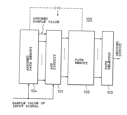
FIG.6 is a block diagram showing the principle
of the present invention.
A maximum-likelihood decoding portion 105,
comprising an ACS circuit 105, a path selector 103, an
assumed path memory 104, is designed for conducting
maximum-likelihood decoding on sample values of an input
signal subject to intersymbol interference. A measure
of interference is assumed on the basis of several bits
of sample values that are earlier in the sequence than
the assumed data sequence in the assumed path memory
104; the assumed sample values allowing for this measure
of interference are obtained; the assumed sample values
and the sample values of the input signal are inpu~ into
the ACS circuit 101 so as to go through
maximum-likelihood decoding.
Specifically, an assumption of a measure of
interference and the computing of assumed sample values
is conducted in the following way. A first
assumption/computation method allows assumption of an
amount of interference caused by a future signal on the
basis of several bits of sample values of an input
signal that are earlier in the sequence than the assumed
data sequence in the assumed path memory 104, and the
assumed data sequence in the assumed path memory 104.
.
.
~ ' -
..
207~7~
g
1 Assumed sample values to be furnished to the ACS circuit
101 are then obtained or, the basis of this measure of
interference, the assumed data sequence in the assumed
path memory 104, and the contents o~ the path memory 102.
A second assumption/computation method allows
an assumption of a measure of interference caused by a
future signal on the basis of several bits of sample
values of an input signal that are earlier in the
sequence than the assumed data sequence in the assumed
path memory 104, and the assumed data sequence in the
assumed path memory 104, also allowing an assumption of
a measure of interference caused by a past signal on the
basis of several bits of the sample values of an input
signal that are later in the sequence than the assumed
data sequence in the assumed path memory 104 so that the
assumed sample values are obtained on the basis of the
measure of interference of the the future signal, the
assumed data sequence in the assumed path memory 104,
and the measure of interference of the past signal.
A third assumption/computation method allows
an assumption of a measure of interference caused by a
future signal on the basis of several bits of sample
values of an input signal that are earlier in the
sequence than the assumed data sequence in the assumed
25 path memory 104 and the assumed data seguence in the ~;:
assumed path memory 104, an assumption of a first :~
measure of interference caused by a past signal on the
basis of several bits of the sample values of an input
signal that are later in the sequence than the assumed . .
30 data sequence in the assumed path memory 104, and an .
assumption of a second measure of interference caused by
a past signal on the basis of the contents of the path
memory 102, allowing a selection of the second measure
of interference when the output from the last stage of
the path memory 102 converges, a selection of the first
measure of interference when it does not converge, so
that the assumed sample values can be obtained on the
7 4
-- 10 --
1 basis of the selected measure of interference, the
assumed data s~quence in the assumed path memory 104,
and the measure of interference caused by a future
signal.
According to the principle of the present
invention, when the assumed sample values, computed on
the basis of the assumed data sequence in the assumed
path memory 104, are furnished to the ACS circuit 101, a
measure of interference caused by a future signal is
assumed by conducting multiplication and addition on one
or a plurality of bits of the sample values of the input
signal that are earlier in the se~uence than the assumed
data sequence. That is, a consideration is given to a
intersymbol interference across two congruous bits or
that across the bits that are several bits apart so as
to compute assumed sample values accurately.
Accordingly, by conducting maximum-likelihood decoding
on the basis of the difference between this assumed
sample value and the sample values of the input signal,
an improvement in an error rate is achieved without
causing a lengthy assumed data sequence (the constraint
length).
The first assumption and computation method
allows an assumption of a measure of interference caused `~
by a future signal on the basis of several bits of
sample values that are earlier in the sequence than the
assumed data sequence in the assumed data path memory
104, and the assumed data sequence in the assumed path
memory 104, after the sample values of the input signal
are input into shift registers, for example. The
assumed sample values are computed on the basis of this
assumed measure of interference, the assumed data
sequence in the assumed path memory 104, and the
contents of the path memory 102. That is, the assumed
sample value is obtained in consideration of the measure
of interference caused by a future signal and the
measure of interference caused by a past signal.
:
: . . . .
: . . . ..
-
; . . . , .. - :
:, . : . . , .. :.
207~7~
-- 11 -- ..
1 The second assumption and computation method
allows a computation of the measure of interference
caused by a past signal on the basis of sample values of
the input signal that are later in the sequence than the
assumed data sequence in t:he assumed path memory 104.
In the presence of any err~r in the contents of the path
memory 102, the error is reflected in the computation of .
the measure of interference, therefore the error could
be spread. If, however, the sample values of the input
signal are employed, the spread of the error is avoided.
The third assumption and computation allows
the obtaining of the amounts of interference caused by a
past signal; namely the first measure of interference
computed on the basis of sample values of the input
signal and the second measure of interference computed
on the basis of the contents of the path memory 102,
permitting a determination of whether or not the output
of the last stage of the path memory 102 converged, upon
which the second measure of interference is selected if ;
20 the convergence is found to take place or the first ~:
measure of interference is selected if the convergence
is not found to take place. The assumed sample values
are obtained on the basis of the selected measure of
interference, the assumed data sequence in the assumed
25 path memory, and the measure of interference caused by a ~:
future signal. ~i-
A detailed description of the embodiments of
the present invention will be given by referring to the -~
drawings. :
FIG.7 is a block diagram of the main portion
of the first embodiment of the present invention. This
embodiment is configured in such a way that a
interference measure predicting device 116 and a shift
register 117 are attached to a decodar 115 comprising an
ACS circuit 111, a path memory 112, a path selector 113,
an assumed path memory 114. An input signal such as a
read-out signal in a magnetic recording apparatus
: - -. - - . . . . .
, . .: , , . . i.
. - ~ :
12 -
1 subject to intersymbol interference or received signals
in a data transmission system are sampled at one-bit
rate, after which the sampled values (digital values)
are input into the shift register 117.
The figures shows a case in which assumed data
sequence in the assumed path memory 114 contains 3 bits
(the constraint length k = 3), namely a 1~ aOl and
al ("0, 0, 0" "1, -1, 1"). In correspondence with
this data, the assumed sample value is obtained on the
basis of 3 bits in the path memory 112, namely b~,
b3, and b4 (see (a) in FIG.4), and x 2~ which is
one of the 3 bits, namely xO, x_l, and x_2, in the
shift register 117. Interference measure predictiny
device 116 predicts a measure of interference on the
basis of the sample value x 2 that corresponds to the
data one bit earlier than the assumed data sequence, the
assumed data sequence a_1, aO, and al, and b2,
which is a content of the path memory 12 corresponding
to the data one bit later than assumed data sequence.
As described earlier, when trying to obtain
the assumed sample value in con ideration of future
data, the assumed sample value y is expressed by
m~h~/ n _vo-/
Y t,~9-lai +~ t~g-lbi +~ g-1Ci ( 3)
by which a measure of inter~erence caused by a future
signal is assumed on the basis of the value a. in the
assumed path memory 114, the value bi of the path
memory 112, the corresponding measure of interference
gi, and the actual sample values that have sequential
correspondence to these. Further,
_Iq--/ O
~g.iCi + ~ g .C. (4)
i ~-n.~r, ~ ~
indicates a conversion from a system (i) in which the
moment at which the assumed sample value is obtained is
designated 0, to a system tj) in which the bit
- :. . .. - , ....................... .: -
:. : - ~:
- :. :
,
2~74~ 7~
- 13 -
1 immediately preceding the assumed sample value in the
assumed path is designatecl 0. Waveforms in FIG.8
obtained when data sequences are ascertainQd in a 10-bit
range for Cj (j = 0 - 9) while assuming every
conceivable combinations of 0 and 1. Lorentzan waveform
as the one shown in FIG.9 was assumed as the isolated
waveform thereof. This Lorentzan waveform g(t) is
expressed as
~(t) = - (5)
1 + (2t/T5Q)
FIG.10 shows variations of the measure of
interference ascertained in the case of T50 = l, 1.5,
2, where the horizontal line indicates an amplitude x
when j = 0 and the vertical line indicates the measure
of interference Y1 when j = 1, 2, 3. For example, m
=1 when the constraint length k = 3, the assumed sample
value being assumed on the basis of the measure of
20 interference when j = 2, so an approximation by a ~:
straight line is possible if we focus on Y2. That is, ~
given gO = 1, the following equation obtains. ~;
~ng-iCi = g-(-m-l)X-m-l (6~:
Since this equation (6) does not take into
account the measure of interference from the assumed
path memory 114 or the pa~h memory 112 to the amplitude
x. If these are taken into account, the equation will
be as follows.
--m-/
~g~iCi = g-(-m-1)
~ ~ .
X (X~ g_jaj +j~tg_jbj)) (7)
Inserting this into the aforementioned
equation (3), the assumed sample value y will be
: , , : . .: . .
: : . : : : .,.
:; -~ .:. , : : : :- .
2a~l7ll
- 14 -
1 obtained as
_m~
Y = g-iai +l~ t~ g-ibi
~ L /
+ g-(m-l)[X-m-l (~g-(i~m+l)ai
~(i+m+1)bi)] (8)
If we assume that the constraint length k = 3,
then m =1, and the first term in (8) will indicate an
addition of the result of multiplication in which the
assumed data sequence a 1~ aO, a1 are multiplied
by the sample values of an isolated waveform in a range
i = -1, O, 1. When n = 4 and therefore i = 2, 3, 4, the
second term indicates an addition of the re~ult of
multiplication in which the contents of the path memory
112, namely b2, b3, b4 is multiplied by the sample
values g4~ g3~ g2 of the isolated waveform. The
- first term in the small parenthesis in the third term
indicates an addition of the result of multiplication in
which the sample values of the isolated values g 1'
g 2' g 3 are multiplied by the assumed data se~uence
a 1~ aO~ a1. The second term in the small
parenthesis indicates an addition of the result of
multiplication in which the sample values of the
isolated waveform, namely g 4, g 5~ g 6 are
multipliedj in a range i = 2, 3, 4, by the contents of
the path memory 113, namely b2, b3, b4. The
result of the addition thereof are subtracted from X 2
before being multiplied by the sample value g2 of the
isolated waveform. Arrows in FIG.7 indicate addition
- and multiplication operations in (83.
FIG.11 indicates a specific configuration
designed for obtaining the assumed sample values in
accordance with the above-mentioned equation t8),
wherein multipliers 121 - 133, add~rs 134 - 136, and
subtracters 137 are integrated. The operations of the
,~ . . i . . . ~ , . . , ~ .
. , . : . ~- .~,
~7~
- 15 -
1 first term in (8) are conducted by the assumed data
sequence a_l, aO, a1 of the assumed path memory
114 being multiplied by the sample values of the
isolated waveform, namely g1, gO~ g_1 by means of
the multipliers 121 - 123, and the multiplied result
being added by the adder 134. The operations of the
second term in (8) are conducted by the contents of the
path memory 112, namely b2, b3, b4 being
multiplied by the sample values of the isolated
waveform, namely g~, g3, g2, and the multiplied
result being added by the adder 134. The operations of
the third term in the parenthesis of (8) are conducted
by each of the results of multiplication by means of the
multipliers 127 - 132 being added by the adder 135. The
operations of the third term in (8) are conducted bv the
result from the above calculation being subtracted from :
the sample value X 2 of the input signal by means of
the subtracter 135, and being multiplied by g2 by
means of the multiplier 133. The adder 136 adds up the
results of the operation of each term. This way the
assumed sample value y to be added to the ACS circuit
111 is obtained.
The ACS circuit 111 creates a new metric value
by adding the output obtained by squaring the difference
between the sample value X0 of the input signal input
via the shift register 117 and the above-mentioned
assumed sample value y, to the previous metric value.
The circuit then compares the metric values and
designate the smaller one as the next metric value, adds
the last in-line data in the selected assumed data
sequence to the path memory 112, and outputs the decoded
output obtained, on a decision-of-majority basis, from
output of the last stage of the path memory 112.
FIG.12 is a block diagram of the main portion
of the second embodiment of the present invention, in
which the sample values of the input signal is used as
the past data; an ACS circuit 141 comprises a path :
-,: . .. - :
,, ,
, ~
.
. .
= ~74~74
- 16 -
1 memory 142, a path selector 143, an assumed path memory
144, an interference measure computing device 145, an
interference measure predicting device 146, a shift
register 147 and 148.
The sample value of the input signal is input
into the ACS circuit 141 via the connect stage of the : ;
shift registers 147 and 148; the sample value of X ~
of the shift register 147 is input into the interference
measure predicting device 146; the sample value o~ the
output from the shift register 148 is input into the
interference measure computing device 145. The assumed
sampl~ value y to be added to the ACS circuit 141 is
obtained according to the aforementioned equation (3);
the first term thereof is obtained from the value of the
assumed path memory 144; the second term is obtained not
by using the value of the path memory 142 but by means
of the interference measure computing device I45 and -
using the past sample value X2; the third term is
obtained by means of the interference predicting devicP
146 and using the future sample value X 2.
The second term of the aforementioned equation
(33 is :~
~t,g-ibi g-(m+l)Xm+1 ~ (9) :
The third term of the equation (3) is
represented by the aforementioned equation t6). The
equ tion (9) and the aforementioned (6~ do not take into
account the measure of interference from the path memory
30 144 and the path memory 142 with the sample value X.
Takiny it i~to account, the equation (9) becomes
7L
35 X [Xm+~ t g~i'a~
~7 ~
- 17 -
1 The equation (6) becomes the aforementioned (7).
Accordingly, the sample value y is
y = ~ g-ai + g-(m+l)
~ t~ -/
m+1 (,~ g-(i-m-l)ai)] + g-(-m-l)
_m~
[X-m-l ~ (~g-(i~m~l)ai)] (11)
That is, the configuration shown in FIG.12 gives the
assumed sample value y. In a similar manner as the
aforementioned embodiment, arrows indicate
multiplications and additions. The computing of the
assumed sample value is realized by multipliers and
adders in a configuration similar to the one shown in
FIG.11.
Because the equation (11) is employed in
computing the measure of interference on the basis of
the past sample value so that the assumed sample value
is obtained, the spread o~ an error in decoding is
avoided unlike the case in which the contents of the
path memory 142 is used in determining the measure of .
interference.
FIG.13 is a block diagram of the main portion
of the third embodiment of the present invention
comprising an AC circuit 151, a path memory 152, a path
selector 153, an assumed path memory 154, an
interference measure computing device 155, an
interference amount predicting device 156, shift
registers ~57 and 158, an XOR circuit 159, and a
switching circuit 160.
This embodiment allows the switching between
the two measures of interference caused by past data,
namely the first measure of interference computed on the
basis of the past sample value X and the measure of
2 .
interference computed on the basis of the values b2,
b3, b4 of the path memory 152, by means of the
:. . . ~ . .
''. ;~` , ~ . ' ' ' ' '' .~ ' . '
': ' ' .
- 2~7~ 7~
- 18 - ;
1 switching circuit 160 whose switching performance is
controlled by the output from the XOR circuit 159, so
that the assumed sample value y is obtained. That is,
if the output from the last stage of the path memory 152
converges, the output from the XOR circuit 159 becomes
"O", and the switching circuit 160 resultingly selects
the measure of interferenc:e obtained on the basis of the
path memory 152; if the output from the last stage of
the path memory 152 does not converge, the output from
the XOR circuit 159 becomes "1", and the switching
circuit 160 resultingly selects the measure of
interference obtained on the basis of the past sample
value.
Accordingly, when there is an occurrence of a
decoding error causing the output from the last stage of
the path memory 152 not to converge, the measure of
interference is computed on the basis of the past sample
value, which measure of interference is used in
obtaining the assumed sample value, thus enabling
avoiding a spread of an error.
FIG.14 is a block diagram of the main portion
of the fourth embodiment of the present invention -
comprising a decoding portion utilizing the
aforementioned equation (3). Specifically, intersymbol
interference caused by future data is assumed on the
basis of the signal on a path for regenerating clock
signals so that an improvement is made in an error rate
in decoding. The fourth embodiment equalizes the input
signal subject to intersymbol interference and puts out
pulses thereof in the pulse generating portion 204, and
comprise a clock generating portion 201 for generating
sampling clock signals synchronous with the pulses, an
A/D converting portion 202 for sampling the input signal
on the basis of the sampling clock signals ~rom this
clock regenerating portion 201, the decoding portion 202
for conducting maximum-likelihood decoding on the basis
of the sample value from this A/D converting portion 202
, . . , ~ ,, ~ ~ . .
- . . .
.
7'~
- 19 -
1 and the assumed sample value, wherein the decoding
portion 202 allows the obtaining of the assumed sample
value by assuming the measure of interference caused by -~
previous data that is earlier in the sequence than the
current sample value, on the basis of the sample value
after the equalization of the input signal or on the
basis of the pulses after they are generated.
Maximum-likelihood decoding is conducted using the
assumed sample value thus obtained.
The decoding portion 203 comprises a shift
register for accepting inputs of the sample value after
the equalization or of the pulses after the pulse
generation, an ACS circuit for accepting inputs of the
sample value of the input signal, an assumed path
memory, a path memory, a path selector, wherein the
assumed sample value is obtained on the basis of the
contents of the shift register, the contents o~ the
assumed path memory, the contents of the path memory,
after which the assumed sample value is input into the
ACS circuit.
In the fourth embodiment, either the sample
value obtained by sampling, by the A/D converter 202,
the e~ualized output resulting from the input signal
subject to intersymbol interference, or the pulse to be
furnished to the clock regenerating portion~201
indicates the result of hard decision on the equalized
input signal, which result is input into the decoding
portion 203 as the tentative decoded value. This
tentative decoded value can be utilized to assume the
measure of interference caused by future data and to
obtain the assumed sample value so that the assumed
sample value allowing not only for the assumption of the
measure of interference on the current data caused by
past data but also the measure of interference caused by
future data can be put to use. Therefore an improvement
in a decoding error rate is achieved without having a
lengthy constraint length.
. : . .. , ,, ,. . ~ . ~ .,, -
' ` ~
2 0 7 ~
In the fourth embodiment, the decoding portion
203 allows the inputting of the tentative decoded value
into the shift register, the inputting of the sample
value of t:he input signal into the ACS circuit. The
assumed sample value is obtained allowing for the
assumption of the measure of inter~erence on current
sample data caused by past and future data, on the basis
of the contents of the shift register, the contents of
the assumed path memory, and the contents of the path
memory. The assumed sample value is then input into the
ACS circuit; maximum-likelihood decoding is conducted by
adding the output obtained by squaring the difference
between the assumed sample value and the sample value of
the input signal, to the previous metric value, and by
selecting the one found to be smaller in value as a
result of comparison.
FIG.15 is a block diagram showing the fourth
embodiment of the present invention in detail, wherein
recorded information is reproduced by a head 211 from a
magnetic recording medium in a magnetic disk apparatus,
~or example, and the read-out signal is used as an input
signal in decoding. As shown in the figure, the fourth
embodiment comprises an amplifier 211, an equalizer 213,
a pulse shaper 214, a phase locked loop 215, a filter
216, an A/D converter 217, a Viterbi decoder 213.
The input signal is subject to intersymbol
interference as described before, amplified ~by the
amplifier 212 to be furnished to the equalizer 213 and
the filter 216. The input signal that went through a
waveform equalization in the e~ualizer 213 is turned
into pulses in the pulse shaper 214 by means of peak
detection, for example, and furnished to ;the phase
locked loop 215. The clock signals whose phases are
locked to the pulses are applied from this phase locked
loop 215 to the A/D converter 217 as sampling clock
signals; sampling of the input signal is conducted in
the A/D converter 217 by an interposition o~ the filter
, - :' -',
` - . : .
.' , ~ , .
. ; .,. ~: , ' .~ :.
2~7~7~
- 21 -
1 216; the converted digital signal is now furnished to
the Viterbi decoder 218; pulses correspond.ing "1" and
"oll of the input signal from the pulse shaper 214 are
applied to the Viterbi dec:oder 218 as tentative decoded
value.
The pulse shaper 214 includes a
differentiating circuit and a zero cross detection
circuit, for example, and functions in the following
manner. The output signal fxom the equalizer 213 is
differentiated by the differentiating circuit; the
output resulting from a differentiation of the peak of
the signal being zero, the zero cross detection circuit
outputs a pulse after detecting a point in the signal
where the zero output is obtained. The Viterbi decoder
218 has a configuration such as the one shown in FIG.16,
and comprises a Viterbi decoder 221 and a shift register
222, as the conventional embodiment shown in FIG.2. The
Viterbi decoder 218 includes an assumed path memory 223,
an ACS circuit 224, a path memory 225, a path selector ;~
226. The shift register 222, the assùmed path memory
223, the path memory 225 each has a multiple-array
configuration and is configured in such a way that they
can store "1", "0", and "-1". As shown by arrows, they
constitute an assumed sample value computing de~ice for
computing assumed sample values by means of
multiplication and addition.
When allowing for interference to the current
sample value from past and future data, the assumed
sample value y is obtained on the basis of the sample
value gi taken at one-bit rate from the isolated
waveform of FIG.4 (c), and the path values ai, bi,
Ci corresponding to the current, past, and future
sample values respectively. The equation (3), by which
this sample value is obtained is shown again below.
~ ~ g~ n~kg-ibi +iS~ g-iCi (3)
~..,
' ' . ~. `
. .
- 2~ - ~7~7~
1 As described beforP, if we assume that the
constraint length k = 3, then m = 1, and multiplication
and addition will be conducted on the three bits a 1'
aO, al corresponding to the range from i = -1 to i =
+1, and the sample values g1, g~ g 1 of the
isolated waveform. Given that n = 4, multiplication and
addition are conducted on the three bits b2, b3,
b4 corresponding to the range from i = 2 to i = 4 of
the path memory 225, and the sample values g 2~ g 3
g 4 of the isolated waveform. Multiplications and
additions are conducted on the three bits c 4, c 3,
c 2 corresponding to the range from i = -4 to i = -2
of the shift register 222, and the sample values g4,
g3' g2 f the isolated waveform; the result of
addition thereof are added up to produce the assumed
sample value y. That is, there is a need to phase lock
the pulses input into the shift register 222 and the
sample value from the A/D converter 217, while assuming
i = O as the current value. A delay processing in the
- 20 assumed sample value computing portion is performed by
means of a selection of the number of stages of the
shift register 222, for example.
FIG.17 is a block diagram of the main portion
of the assumed sample computing portion for computing an
assumed sample value y according to the equation (3~
wherein the shift register 222, the assumed path memory
223, the path memory 225, the multipliers 31 - 39, the
adder 40. The 3 bits C_4, C_3, c_2
register 222, the 3 bits a 1~ aO, a1 of the
assumed path memory 223, the 3 bits b2, b3, b4 of
the path memory 225 are supplied to the multipliers 231
- 239 to be multiplied by the sample values g4 - g 4
(see FIG.4 (c)) of the isolated waveform; the outputs of
the multipliers 231 - 239 are supplied to the adder 240
to be added up. The output from the adder 240 is input
into the ACS circuit 224 as the sample value y. The ACS
circuit 224 then calculates the difference of the input
:: - : . . . . . , . :. . :
:, . - :: . .,-
: :, . : : :
.. - ~ . ~
~7~7~
- 23 - -
1 value from the sample value. That is, the assumed
sample value is obtained, wherein the interference from
past data and the interference from future data are both
considered.
FIG.18 is a block diagram of the fifth
embodiment of the present invention. This embodiment
comprises a head 251, an amplifier 25~, an equalizer
253, a pulse shaper 254, a phase locked loop (PLL) 255,
a filter 256, an A/D conver~er 257, a Viterbi decoder
258, an A/D converter 259 for sampling the output from
the equalizer 253 so as to convert the output to the -
digital signal. The input into the Viterbi decoder 258
is not the pulse from the pulse shaper of the embodiment
shown in FIG.15, but the digital signal obtained through
the conversion of the output signal from the equalizer
253 in the A/D converter 259. ;~
The Viterbi decoder 258 has the same
configuration as the Viterbi decoder 218 of the
previously mentioned embodiment. The sample value
obtained by the A/D converter 259 is input into the
shift register 222.
FIG.l9 is a diagram describing a measure of
interference, showing the measure of lnterference caused
by the signal at time -i and affecting the signal at
time 0. The possible values of the signal at time -i
are considered to spread out showing a normal
distribution with "1'l, "0", "-1" in the center, on a
condition that interference from other sources are nil
because of the equalization. The probability p (X, X')
when the relevant sample value is X' is given by
(X' - X)2
p (X, X') = -~ e 2 ~2 ~12)
~ 2 ~ ~
Supposing that the measure of interference affecting the
- , .
: , . , ~: -.:
- :
~7~17~
- 2~
1 value at time 0 and corresponding to "1", "~ 1" are
gi~ gi"' gi"' respectively, the expected value
gXi of the measure of interference when the sample
value is X' is
gi Pi + gi Po + gi P-1
gXi - ~--- (13
Pi + Po + P_l
Inserting the conditions expressed in (14)
that follows into (13),
gi gi ~ '
gi" = O ,~
gi gi
giP1 giP-1
gXi - ' tl4)
Pl + Po + P_ 1
The sample values in the horizontal line are shown in
20 FIG.20 against the expected values of corresponding ::
measure of interference, with an S/N ratio as a
parameter. As is evident from the figure, when the SlN :
ratio is high, it is better to obtain the measure of
interference using the decoded values "0" or "-1" and :
when the S/N ratio is low, it is better to obtain the
measure of interference probabilistically using the
sample value.
Allowing for:the effect of noise, we can
postulate
gxi = gix ~ ,.
which gives the sample value y as
n
35 Y =. g-iai +~ g-ib +~ g .X. / (1
~-m ~-m~ 1 ,`~-~ ~ 1 1
Accordingly, the sample value Xi' from the
. . .. - . .:
:- .. . .: , " . . :
1 7 ~
- 25 -
1 A/D converter 259 in FIG.18 is input into the shift
register 22 of the Viterbi decoder 258 (see FIG.16).
X ~', X 3', X_4', instead 3f c_2, c_3, c_4,
are input. The assumed sample value obtained in
accordance with the equati~n (17) is input into the ACS
circuit 224 (see FIG.16) of the Viterbi decoder ~58,
after which a new metric value is determined by adding
the previous metric value and the output obtained by
squaring the difference between the assumed sample value
and the sample value from the A/D converter 257, the
smaller of the metric values, determined by a
comparison, will be selected and the last-in-line value
of the selected assumed path is input into the path
memory 225 (see FIG.16).
As described before, even when the intersymbol
interference exceeds the range of the assumed path ~the
constraint length k), an accurate assumption of the
assumed sample value is possible; namely, when we
determine the intersymbol interference from the
20 preceding data in the assumed path (corresponding to .~-
future) by employing a sample value that is affected by
less intersymbol interference owing to an equalization
performed thereon, by allowing for the effect of noise,
and by assuming the measure of intersymbol interference
after providing a little additional configuration.
Accordingly an improvement in an decoding error rate is
achieved.
FIG.21 is a block diagram of the main portion
of the sixth embodiment of the present invention. The
sixth embodiment is designed for assuming, in the
Viterbi decoder of the latPr stage, the measure of
interference from the preceding data in the assumed
path, for use in decoding, by using the output of the
Viterbi decoder of the earlier stage.
This embodiment comprises: a first Viterbi
decoder 301 for conducting tentative maximum-likelihood
decoding on the basis of the sample value resulting from
- . : . : , ,
. :
. , - ~ . ~ . , .-~
.. ..
2~17~:~Pl~
- 26 -
l a conversion, in the A/D converter 303, of signal
subject to intersymbol interference; a second Viterbi
decoder 302 for conducting maximum-likelihood decoding
by accepting as inputs the output of the first Viterbi
decoder 301 and the previous sample value, wherein the
second Viterbi decoder 302 allows an assumption of the
measure of interference caused by future data and
affecting the current data on the basis of the output of
the first Viterbi decoder 301, an assumption of the
measure of interference caused by past data and
affecting the current data on the basis of the contents
of the path memory, so that the assumed sample value is
obtained; the assumed sample value thus obtained is
compared with the previous sample value so that decoding
process is conducted.
The metric value from the ACS circuit of the
first Viterbi decoder 301 is input into the ACS circuit
of the second Viterbi decoder 302; the output of the
last stage of the path memory of the first Viterbi
decoder 301 is input into the computing portion for
computing the assumed sample value to be furnished to
the ACS circuit of the second Viterbi decoder 302.
Maximum-likelihood decoding in the second
Viterbi decoder 302 is conducted on the basis of
tentative decoded value which went through error
correcting decoding in the first Viterbi decoder 301,
which means that two-stage error correcting decoding is
conducted, thus improving an error rate.
The output of the last stage of the path
memory of the first Viterbi decoder 301 is not selected
as the decoded output but the output of the last stage
i5 input into the second Viterbi decoder 302 so that the
measure of interference caused by future data is
assumed. The metric value from the ACS circuit of the
first Viterbi decoder 301 is input into the ACS circuit
of the second Viterbi decoder 302 to be forwarded to a
metric operation for addition. This way a comparison o~
:. "' .' ' ' " ' ' :'
".', ' ' . ' ' "'; ' ' ' ' " ' '
: ' ' ', ` ~ : ' ..
- 27 - 20~ 7~
l metric values is easy.
FIG.22 is a bloc]c diagram showing the sixth
embodiment in detail. The sixth embodiment shown
comprises a magnetic head 311, an amplifier 312, an
equalizer 313 and 316, a pulse shaper 314, a phase
locked loop (PLL) 315, an A/D converter 3ï7, a first and
second Viterbi decoder 318 and 319, an error correcting
decoder 320.
Signals reproduced by the magnetic head 311
from a recording medium such as a magnetic disk is
subject to intersymbol interference. The read-out
signal is amplified by the amplifier 312, undergoes an
equalizing amplification by the equalizers 313 and 316
containing filters, as well as being cleared of noise.
The read-out signal is then turned into pulses by peak
detection in the pulse shaper 314 before being applied
to the phase locked loop 315. Clock signals that are
synchronous with the read-out signals are furnished from
the phase locked loop 315 to the A/C converter 317. The
A/D converter 317 carries out a sampling on the read-out
signals from the equalizer 316 in accordance with the
timing set by the above clock signals. The sample
values are furnished to the first and second Viterbi
decoder 318 and 319.
The first Viterbi decoder 318 includes an ACS
circuit, a path memory, a path selector, and a path
memory. Decoding is conducted in the same manner as the
known art, the decoded output being designated as the
tentative decoded value. The second Viterbi decoder 319
uses this tentative decoded value for assumption of the
measure of interference ~rom preceding data in the
assumed path so that decoding processing is conducted.
The need for phase locking the tsntative decoded value
to the sample value input into the second Viterbi
decoder 319 is easily realized by delay circuits such as
shift registers because the length of the assumed path
(the constraint length) and the length of the path
:: : . . . : ,
2~7417~
- 28 -
1 memory give the measure of delay used for obtaining the
tentative decoded value.
The error detecting decoder 320 is provided in
the case in which the input signal is error detecting
coded, and conducts an error detecting decoding on the
decoded output from the first Viterbi decoder 318; the
decoded result is designated as the tentative decoded
value to be input into the second Viterbi decoder 319.
As described before, not only the first
Viterbi decoder 318 conducts error detecting decoding
but also the second Viterbi decoder 319 conducts error
detecting decoding, improving an error rate.
As described before, the assumed sample value
y, with a consideration given to intsrference caused by
future data, is obtained in accordance with the
aforementioned equation (3) on the basis of the sample
value gi taken at one bit rate from the isolated
waveform of ~IG.4 (c), and ~he current, past, and future
path values ai, bi, ci respectively-
The main portion of the second Viterbi decoder
319 for carrying out the processes in accordance with
the equation (3) is configured as shown in FIG.16. The
tentative decoded value from the first Viterbi decoder
318 are shifted to the shift register 222 sequentially.
The sample values are then input into the ACS circuit
224.
Given that the constraint length k (the length
of the assumed path) is 3, the 3 bits of the assumed
path memory 223, namely a 1~ aO, a1, the 3 bits of ?
30 the path memory 223 h2, b3, b4, the 3 bits of the
shift register 222, namely c_2, c 3, c 4 (for the
positions of each bit in the sequence, see FIG.4 ~a)),
and the sample value Y1 of the isolated waveform tfor
the position of the sample value in the sequence, see
FIG~4 (c)) are utilized as the basis for obtaining the
assumed sample value in accordance with the equation
(3). FIG.16 shows that a multiplication and addition
; ~ -, . . , , , ~ , :
. ~ , . , , , :~
2 ~ L~
-- 29 -- -
1 are performed on the assumed sample value.
The assumed sample value computing portion for
computing the assumed samE)le value y according to the
equation (3) has a configuration shown in FIG.17. The 3
bits c 4, c 3, c 2 of the shift register at which
the assumed sample value from the first Viterbi decoder
318 are furnished to the sample values g 4 - g4 (see
FIG.4 (c)) of the isolated waveform, the 3 bits a 1
aO, al in the assumed path memory 223, the 3 bits
b2, b3, b4 of the path memory 225 are furnished to
the multipliers 231 - 239 for multiplication. The
outputs from the multipliers 231 - 239 are furnished to
the adder 240, whose output is input into the ACS
circuit 224 as the assumed sample value y. The ACS
circuit 224 calculates the di~ference between the
assumed sample value and the sample value of the input
signal. That is, the assumed sample value y is obtained
with a consideration given to the interference from both
past and future data
FIG.23 is a block diagram of the main portion
of the seventh embodiment of the present invention. The
embodiment comprises a first Viterbi decoder 351, a
second Viterbi decoder 352, and a shift register 341.
The first Viterbi decoder 351 comprises a shift register
342, an assumed path memory 343, an ACS circuit 344, ond
a path memory 345. The second Viterbi decoder 352
comprises an assumed path memory 353, an ACS circuit
354, a path memory 355, a path selector 356, and a shift
register 357.
The sample value is input into the ACS circuit
344 of the first Viterbi decoder 351 and the assumed
sample value is obtained in accordance with the equation
(l) on the basis of the contents of the assumed path
memory 343, or the contents of the path memory 345 is
also used so that the assumed sample value can be
computed in accordance with the equation 92). A
comparison is then made after the output obtained by
: . ; : - ,, : . . :
. 's, - ~
` 207~174
- 30 - -.
1 squaring the difference between the sample value and the
assumed sample value are added. The smaller of the
metric value determined in a comparison is selected as
the next metric value. Thle metric value selected is
input into the ACS circuit 354 of the second Viterbi
decoder 352 via the shift register 342, this selection
being furnished to the path memory 345 as a piece of
information, and the output of the last stage of the
path memory 345 being input into the shift register 357
of the second Viterbi decoder 352. The sample value is
input into the ACS circuit 354 of the second Viterbi
decoder 352 via the shift register 341.
The shift registers 341, 342 act as delay
circuits for phase locking the first Viterbi decoder 351
and the second Viterbi decoder 352, the selection being
based on the length of the path memory 343 of the first
Viterbi decoder 351 and the length of the path memory
345.
As shown by arrows, the assumed sample value
is computed in the second Viterbi decoder 353 by
performing multiplication and addition in accordance
with the equation (3) on the basis of the contents of
the shift register 357, the contents of thQ assumed path
memory 353, and contents of the path memory 355. In the
ACS circuit 354, an addition is carried out on the
output obtained by squaring the difference between the
assumed sample value and the sample value inpuk via the
shift register 341, and on either the previous metric
value or the metric value input via the shift register
342. A comparison is then made as to each metric value
and the smaller one is selected as the next metric
value. Accordingly, not only the value of the path
m~mory 345 that has a ~ikelihood of being a decoded
value of the first Viterbi decoder 351 but the metric
value that shows the likelihood thereof are transmitted
to the se.cond Viterbi decoder 352, so that
maximum-likelihood decoding is conducted, improving an
: ~ `~ ` ' , : : . '
~ . - : -. : ~ .
- 31 - 207~7~
1 error rate.
The present invention is not limited to the
embodiments already described, but can find an
application in the decoding of signals subject to
intersymbol interference other than the read-out signals
of a magnetic recording apparatus.
POSSIBLE US~E_IN THE INDUSTRY
As has been described, maximum-likelihood
decoding method and device of the present invention can
decrease a decoding error rate without enlarging the
scale of the circuit, and can find its application in
the reproducing of the signals in a magnetic recording
apparatus, for example.
~0
; - , . . '
~ ' ' . , ~ ,
. ~. . . . .