Note: Descriptions are shown in the official language in which they were submitted.
207~2~7
CLEANING DEYI OE
Hard deposits build up on the internal surfaces of process pipework in
a munber of industries as diverse as brewing, power generation and oil
production. It is a particular problem in oil production where
S deposits such as barium sulphate are formed within the production
tubing of producing oil wells ~t. and immediately above the reservoir
depth. These deposits reduoe the flow area of the tubir~g, thereby
reducing oil flow to the surface. These depDsits are very hard. If a
mechanical cutter/reamer is used to remove them, damage is frequently
10 caused to the steel pipe itself. m e alternative solution at present
is to extract the entire length of production tubing to the surface,
and to replace it with a new pipe. Because of the depth of some wells
this is a laborious and expensive procedure.
The present invention is designed to assist the removal of hard
15 deposits from a steel pipe without damaging the pipe itself. Flushing
flow may be provided to transport the removed deposit to the surface if
any fluids beir~ transported by the pipe are not sufficient to do this
themselves. Tests have shown that high velocity jets of water will cut
through barium sulphate deposits. However to achieve a satisfactory
20 performance pressures of the order of 150 million pascals or higher are
required, which is not practical to generate~ in a deep oil well.
Further testing has shown that the addition of low concentrations of
solid particles to the flow can dramatically enharce the performance of
the jets. This enables the descaling operation to be carried out at
25 much lower pressure, typically at 20 million pascals or less. The
invention is therefore suitable for operation in conjunction with
conventional oilfield pumping, pipework and other equipment.
According to one aspect of the invention there is provided a head for
forming jets ~ithin a condlut of abrasive mixture from a pressurised
-
: .. ~ .~:: : :
207~2 '17
-- 1~ --
supply, the head being formed with a re.servoir for receiving themuxture and a plurality of nozzles which have no tangential component
about the conduit axis, the nozzles ccnprising different types,
including one type which is inclined in one direction relative to the
S axis, and another type which is inclined in the c~osite direction
relative to the axis, toth typ~s being fed from mixture in said
reservoir.
In another aspect of the invention there is provided a method of
cleaning the internal wall of a c~nduit c ~ prisin~ directing jets of
10 abrasive nixture from a reservoir at the internal wall, the jets having
no tangential component about the conduit axis, the jets comprising
different types, including one type which is Lnclined in one ~irection
relative to the axis, and another type which is inclined in the
c~x~site direction relative to the axis, both types being fed from
15 mixture in said reservoir.
The two types of jets or nozzles enable cl~aning action to be directed
at different angles so that one type may achieve cleaning action if the
other type dbes not. On the other hand, the two types are fed with
abrasive mixture from a single reservoir so that a simple form of
20 construction can be used.
2 ~ 7
Examples of the invention will r~ow be described with reference to the
accompanyir~ drawings in which:-
. .
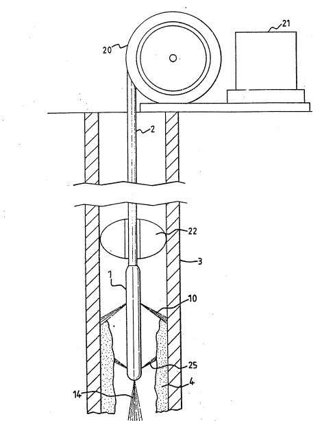
FiO~e 1 is an overall view of a descaling syste~;
Figure 2 is an axial section through the jetting head of
5 Figure l;
FiO~e 3 is a radial section throu~h the head of FiO~ure 1;and
Figure 4 shows the jet pattern which can be achieved by the
head of Figure 1.
10 An abrasive moxture, comprising carrier fluid and abrasive particles is
formed and pressuri~ed in a pumping system 21 such as is described in
our Patent Publications GB-A-2162778, EP-A-258424 and EP-A-276219 is
fed through a coiled tubing unit 20 to a pipe 2 which is fed down the
axis of the pipe 3 to be descaled. The abrasi~e mixture is applied to
l5the bore of the pipe 3 from a special jetting head 1 on the lower end
of the pipe 2 which pipe passes through a spacin~ block 22 for keeping
the pipe 2 cen~ral within the bore of the pipe 3, although the symmetry
of the spray from the head 1 to be described below may be sufficient to
effect the centralising action, rendering the block 22 redundant.
:. . ~' ;: ` :,
:
2~2~7
W O 91/11~70 PCT/~Bg1/OOa88
-- 3 --
The sl~lrry (abrasive muxture) floh enters the jetting head 1 from the
supply pipe 2 at one end throt~h a s~irlir~ vane ; (see Figure 2) which
imparts rotation to the floh. This causes separation of the
constitutents of the flow, with the denser solid particles being
5 concentrated in outer parts of swirl cham~er 6. A ring of six nozzles
7 is set into the outer wall 8 of swirl chamber 6. The nozzles 7 are
fan-jet rozzles (i.e., the jet is elongated tangentially) ~hich spread
the jets of concentrated sll~ry 10 as ~t flat sheet 11 with an included
angle of spread of 120 degrees to ~)rovide a complete ring of coverage
10 of the production t~ir~ 3 and the deposit 4. In Figure 4 only the
flat sheet jets from alternate nozzles in the ring are shohn in full.
The jetting head 1 is steadily lowered or raised on the pipework system
20. In this way the jets 10 are traversed along the tubir~ 3 and the
impact of the solid particles in the sltlrry jets 10 on the deposit 4
15 cause it to be removed from the ~all of tllbing ~. The nozzles 7 are
slightly inclined dGwnwardly, so that the jets 10 tend to bite behind
the scale as the head 1 moves progressively down the tl~ing 3.
The central portion of swirl chamber 6 is extended at a s~aller
internal diameter 1~ and supplies another array of nozzles 13. Because
20 the solid particles move to the outer portion of the chamber 10, the
flow enterir~ the extended portion of s~irl chamber 6 contains very feh
solid particles. Ihe jets 2; produced b~ the noz les 13 are also
fan-shaped. These nozzles 13 are slightly inclined tlpwardly and
provide a flllshir~ flow to carry the solid particles from the slurry
2~ jets 10 and the deposit which the~ have removed from the wall of tubing
3 back to the sl~face. The fan shape of the jets ensltres a flushing
flow arol~nd the fllll circt~ference of the tl~ing ~. It will be seen
that the jets fr~m the nozzles 7 and 13 are directed tohards each
other. The jets fr~ nozzle 7 directe~ ctway froD the end at which the
30 supply pipe 2 enters the jetting head 1 are closer to that end then the
nozzles 13 from which the jets are directed to~ards that end. In an
oilfield application, the tt~ing is vertical and the abrasive mixtl~e
supply comes from and the fltlshed seale is directed back to the upper
. , .
: -
' - ,
2~7~2-~7
W O 91/11270 P~r/GB91/0~88
-- 4 --
open end of the tubing.
.~n additional particle carrying nozzle 16 is fitted into the base of
the jetting head 1. A conduit 1~ supplies solid particle laden slurry
to noz~le lS frc~ the supply pipe 2 upstream of swirl~ng ~ane 5 so that
S although it is of small diameter it has not been stripped of particles
by the swirl action. Nozzle 16 prc~uces a generally axially directed
jet 14 in a spreading conical form. The solid particles in jet 14
impact with any of the deposit 4 ~hich extends in towards the centre of
the tubing 3 causing it to be removed and opening up a passagehay
10 through ~hich jetting head 1 can advance along the tubing 3. -
The pipework system 20 as shown in Figure 1 is a coiled tubing unit.Alternatively the pipework system might be in the form of pipe lengths
~ich are joined together to extend the length of the system, as for
drilling pipe. Both types of pipework system are commonly used in
15 oilfield applications. Other pipework systems might be used~
especially where the invention is used to descale pipes in industries
other than the oil industry.
As shown in Figure 3, the nozzles 7 and 13 are equally spaced around
the jetting head 1. This provides a balance of the reaction foroes of
~Q the jets 10 and 2; and is the preferred arrangement where no rotational
motion of the jetting head 1 is provided as in Figures 1, 2 ard 3.
Since ncne of the nozzles is directed tangentially, the reaction of the
jets provides no rotational drive.
Rotational motion can be provided either from the surface or by a
2j downhole motor (not shown). Where rotational motion is provided the
centralisin~ ~lide 22 absorbs the reaction force generated by the jets.
In this mode of operation a simple mechanical scraper can form part of
the centralising guide and will remove any small segments of the
deposit which are weakened but not removed by the direct action of the
30 jets.
- . . , - : ~ :
.. .
' -: ' ' ~ ~.
2~7~2-~7
-- 5 --
In Figure 4 a single ring of six solid particle carrying nozzles
produces fan-shaped flat sheet jets 11, each ~ith an included angle of
120 degrees. The numbcr of nozzles 7 and the ar~le of the fan sheet 11
are selected based on the mini~um bore of the tubing 3 to be descaled
S to provide full coverage of the tubing 3. The rir~ of nozzles could be
replaced by a single nozzle producing a hollow cone shaped jet or by
multiple rings of nozzles or by multiple hollcw cone shaped jets to
r~nove the deposit in progressive steps. The jets with an axially
downward direction are useful for separatirlg the deposit fro~ the walls
10 of the pipe 3 whereas the jets with an axially upward direction are
useful for flushing the removed deposit up towards the surface and this
action may be assisted by any fluids being transported upwards by the
pipe at the same time. Where more than one ring of noz~les is used
different angles can be used to alter the pattern of attack on the
15 deposit. Where only one ring of nozzles is used individual nozzles can
be set at different angles to achieve the same effect. In a similar
manner the ring of flushing flow nozzles 13 can include nozzles
producing different shapes of jet and also be replaced by more than one
ring of nozzles or by a single nozzle for example one producing a cone
20 shaped jet. This also applies to the single forward facing particle
carrying jet nozzle 16. This can be replaced by a nozzle producing a
different shape of jet or by a m~mber of nozzles.
Although flushir~ flow no7zles 13 are shown in Figures 1, 2 and 3 the
flushing flow is not required for all descaling operations. For
25 example they are not necessary when there is a high production flo~ in
the tubing 3. In a si~ilar manner the single forward facing nozzle 16
is not necessary where it is known that the thickness of deposit is not
too great. This can particularly be the case where the jetting head 1
is used to carry out regular maintenanse as opposed to remedial
30 operations.
2~
The use of an abrasive mixture is better than the use of
fluids alone. The solid particles impact with the brittle
deposit, causing it to crack and break off in discrete
5 pieces from the action of carrier fluid of the jet being
forced into cracks formed by the impact of the particles.
The size of the dislodged pi~sces of deposit is controlled
by setting of the jetting parameters, such as pres~ure,
flow, particle size and other particle properties, and
particularly by the concentration of particles in the
flow. The solid particles do not need to be of any
particular shape to achieve the effect on the brittle
deposit, and therefore rounded particles can be used,
which will ensure that the underlying pipe is not damaged
by the action of the jet. Because of the nature of the
solid particles, the effect on the pipe will be confined
to a beneficial shot-peening action.
,
. : .
'
~ . .
,