Note: Descriptions are shown in the official language in which they were submitted.
7 ~
This invention relates to a bucket extension for a side mounted
refuse bucket.
~ACKGROUND OF THE INVENTION
Canadian Patent No. 1,012,5û0 granted on June 21, 1977 to the
present assignee describes a refuse vehicle which is provided with a~side mounted
refuse receiving, loading and co~pacting bucket. This arrangement has been
successfully operated OD a cs)mmercial basis ~or many years. EsseIItially, the
bucket was designed to provide a large loading capacity capable of recei~ing
several times the voluîne of conventional, domestic trash cans to avoid the fuel-
inefficient need ~f unloading the bucket at frequent intervals. llle bucket was
also designed so tha~ the side walls thereof are at as low an elevation as possible
to minimize the distance which trash cans must be lifted by the operator to empty
them into the bucket. The bucket is moveable from a loading position to a
transport position in which the bucket doubles as the side wall of the dump ~odyand, therefore, virtually completely elimiDates the considerable space consumed
by the compacting assembly of conventional refuse vehicles. I~e bucket is also
moveable from the transport position to a refuse compachng position disposed
within the truck body.
A further advantage of the abo~e described side mounted loading
bucket is that it can be used advantageously with the animal proof container
described in Canadian Patent No. 1,072,511 granted to the presen~ assignee on
February 26, 1980. The animal proof container is an apparatus which is
particularly intended for use in provincial and federal parks and includes a base
~5 which may be rigidly secured to a concrete pad and a hopper which is pivotally
secured to the base and which can be pivoted by hydraulic cylinders between a
lower loadiTlg position and an elevated discharge posi~ion. The capaci~ of the
hopper is substantial as compared to the capaci~ of the side mounted refuse
bucket. The combination of the side mounted bucket and the refuse container
render collection of refuse in parks e~tremely simple and efflcient as compared
to prior art a~angements. The refuse loading section of conventional refuse
vehicles are not c~pen ~and, accordingly, it is irnpossible to emp~ the contents of
; ~.
. :~
- - ~
.
:
2~7~
~ 2 ~
the animal proof ref~lse container directly into such collection vehicles, not to
mention the fact that, even if i~ was possible to do so, it would reqllire that the
refuse vehicle be backed up approximate to the refuse hopper.
A difficulty which has been encountered with the side mounted
5 refuse bucket arrangement is that, because of the capaci~ of the refuse hopper,
there is that it sometimes happens that the refuse from the hopper spills out ofthe loading bucket when the hopper is discharged into the bucket. Increasing theheight of the side walls of the loading bucket to avoid such spillage is not an
acceptable solution since it would defeat the objective of maintaining a low trash
lû can lifting height as mentioned earlier. In addition, increasing the height of the
side walls of the loading bucket may interfere with the refuse compacting
capability of the bucket. Accorclingly, there is a need for a solution to the above
described problem.
1~ SIJM~RY OF THE INVENTION
- It has l~een found that it is possible to modify the side loading
bucket arrangement in such a manner as to increase the capacity of the bucket
when used in conjunction with parks hoppers while at the same time maintaining
the lifting height of the bucket as low as possible. l~is is achieved by providing
~0 a flexible extension which includes a generally U-shaped frame whose arms arepivotally connected ~o the side walls of the bucke$ adjacent the pivot axis of the
bucket and a flexible skirt or shroud is secured to both the f~ame and the bucket.
The frame is resiliently urged to an extendsd position which increases the height
of the side walls and front wall of the bucket so as to effectively increase the25 capacity of the bucket. The extension is moveable from the extended position to
a retracted position during the compacting stroke of the bucket and may also be
secured in its retracted position when the vehicle is used for collecting refusefrom conventional domestic trash cans.
,
-
- ' - ~ ''. ',` :
2~7~
-3 -
BRIEF SUM~ Y [)F THE I)RAWINGS
These and other features of the invention will become clearer from
the following description in which reference is made to the appended drawings
w31erein:
5FIGURE 1 is a perspective view of a side loadirlg refuse vehicle illustrating
the load bucket in an elevated, compact refuse compactingposition;
FIGURE 2 is a cross-sectional view ~aken along line 2~2 of FIGURE 1
illustrating the bucket assembly operating strokes; and
FIGUR~E 3 is a diagrammatic perspective view of a preferred embodiment
10of the side loading refuse bucket ~xtension of the present invention.
DETAILED DlESCRlPIlON OF THE INYENTION
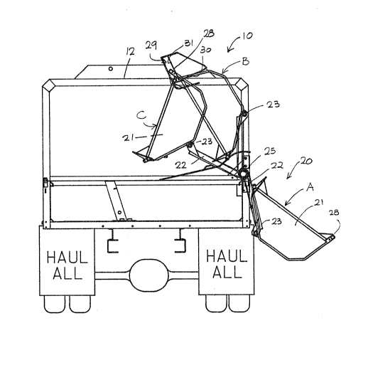
With reference to FIGURE 1 of the drawings, reference numeral 10
generally designates a self-loading vehicle having a cab 11 and a body 1~. Body
1512 is adapted to receive and store refuse or the like and is tiltable in the usual
manner by conventional hydraulic cylinders (not shown). It is provided with
doors 13 and a tailgate 14 at the back end thereof through which the refuse is
discharged.
Mounted at one side of body 12 is a bucket assembly 20 which includes a
2~0bucket 21 and a plurali1~ of articulated arms 22. As best show in FIGlJRE 1,
bucket 21 is mounted for pivotal movement at one end of each alm 22 by pivot
pins 23. l'he other ends of arms 22 are fixedly secured, by welding, to a shaft 25
which extends longitudinally of the vehicle and which is mounted for rotation inbearing blocks 26. Bucket 21 is formed with a spring bias pin 28 which extends
2~longitudinally away from the bucket at one end thereof. The pin is adapted to
cooperate, during a compacting stroke, with a cam groove 29 formed on the
inside wall of body 12. ~ooperation between pin 28 and groove 2~ results in
rotation of bucket 12 about pins 23 as anns 22 are angularly advanced in the
counterclockwise direction as viewed in FIGUlRE 2. Position A signifies the
30normal refuse receiving position of the bucket. From this position and during its
advancement to position B, bucket 21 is held releasably secured to arms 22 by a
releasable bucket securing means ~not shown~. Position B is the position at which
..
- 4 ~ 2 ~
the contents of the bucket are emptied into ~ody 12 arld pin 28 and engages
groove 29. This is the normal transport position of the bucket. Position C
signifies the inner most or terminal position of the bucket. Travel of the bucket
from position B to position C effects compaction of refuse in the vehicle body.
Once bucket 21 has been adequately filled at position A, a bucket
actuating mechanism (not shown) is energized to pivot shaft 25 in a clockwise
direction as vie~Ned in FIGUlRE: 2 aDd carry with it bucket 21. As already
mentioned, between positions A and B, bucke~ 21 is held releasably secured to
arms ~2 in such a manner that the bucket is prevented from pivoting about pins
10 23 in a clockwise direction relative to arms 22. Upon reaching position B, the
contents of the bucket will have been deposited into the vehicle body and pin 28will have engaged groove 29. With further advancement of the bucket, the bucket
is released from arms 22 and pin 28 will follow cam groove 29 and ¢ause the
lower edge of bucket 21 to move inwardly of body 12 relative to the upper edge
1~, and, in so doing, the contents of the body will be compressed. A~ter reaching
position C, the actuating mechanism is reversed and the bucket will return to
position A or B as desired by the vperator.
As best shown in FIGURE 2, the upper longitudinal edge of the buclcet,
when disposed in position A, is at a relatively low height. This is highly desirable
20 in order to reduce the distance over which an operator must lift a trash can. It
is highly desirable to maintain a low lifting height. C)n the other hand, when the
vehicle is used to collect the contents of park refuse containers of the type
- described in Canadian Patent No. 1,072,511, it has been found that refuse tends
to spill out from the loading bucket. This difficulty is overcome by the bucket
25 extension illustrated in FIGURE 3.
In accordance with the present invention, there is provided a flexible
extension 50 which includes a unita~y, generally U-shaped frame member S2
having a pair of arms 54 which are pivotally connected to the side walls of the
bucket adjacent the pivot axis of the bucket. Arms ~4 extend forwa~dly of the
30 bucket, parallel to and on the outer side of the side walls of the bucket and are
adapted to abuttingly engage the underside of pins 28. The extension further
includes an arcuate frame portio;n 56, centred on the pivot axis of the bucket,
,
- - . -................................. ~:
., - ,
- 5 ~ 2 ~ 5
extending upwardly from the free end of the arms. A bar 58 is connected to and
extends between the upper, free ends of the arcuate portions. Pins 60, sinnilar to
pins 2X, are mounted on each end of the bar, as shown, for engagement with
grooves ~9 in the truck body, as explained more fully later. A tension spring 625 extends between a braclcet 64 on the bucket and a lug ~6 secured t~ an arm of
the extension, as shown in FIGURE 3, in order to reslliently urge the extension
towards its extended position. A similar spring may be provided on the other
arm. A skirt or shroud 70 of any suitable rugged, flexible material has a portion
of its top edge fixedly secured to the inside edge of the bar and its bot~om edge
1û secured to the inside of the top edges of the side and front walls of t~e bucket.
As mentiolled, the frame is resiliently urged to an extended position which
increases the height of the side walls and front wall of the bucket so as to
effectively increase ~he capacity of the bucket~ The extension is moveable from
this extended position to a retracted position during the compacting stroke of the
lS bucket by engagement of pins 60 with grooves 29~ They may also be secured in
- its retracted position when the vehicle is used for collectirlg refuse from
conventional domestic trash cans~
It will be seen that the bucket extension described above provides a simple
and effective solution to the problems mentioned earlier~ It will be understood
20 that various modifications rnay be made to the invention without departing from
the spirit o~ the appended claims~ For example, its will be understood that the
arcuate members described above not be arcuate; they may be straight mernber
interconnecting an end of the cross bar with the free of une of the arms~
~ ,
- .
- :