Note: Descriptions are shown in the official language in which they were submitted.
2Q~418
SPEEC}~ SY~ l~ USING PE~ JAL
LINEAR PRE~I)ICTION PARAMETERS
Field of the Itl~en,t,oll
This invention generally pertains to speech synthesis, and particularly,
5 speech synthesis from parameters that rup~nt short segments of speech with
m-litirle c~ffi(-;entc and w~i~htin~ factors.
r~3~l.,und of the Invention
Speech can be synthP~i7~d using a number of very different appr~aches.
For ~mple, ~ cor~i~sgs of words c~n be re~c~-mbled into s~ntc~ces to
10 produce a synthetic ut~lance of a tclephone number. Alternatively, a phoneticnl ~;on of the t~lephon~ number can be ploduccd using phonPmes for each
sound ~ ;Ch~e the ul~ce. Perhaps the do~ n3nt techulique used in speech
synthesis is linear predictive coding (LPC), which describes short seg...--n~s of
speech using parameters that can be llan~ro~ ed into positions (frequencies) and15 shapes (bandwidths) of peaks in the spectral envelope of the speech segl~ n~c~ ~ a
typical 10th order LPC modd, ten such p~ are dct~,.n;n~d the fi~ue~s~
pea~s defined thereby co~ ~nf~ E to l~l~anl rl~u. nc;es of the speaker's vocal
tract. The pa~ t~.~ d~r~ g each se~ of speech (t,vpically, 10 - 20
millis~on-ls per s,~g~ nt) l~l~nl data that can be applied to conventional
20 syn~h-oci7P~ ha~dw~ to replicate the sound of the speaker plO JuCil~g the ulte~ ce.
It c. n be shown that for a given spe~er, the shape of the front cavity of the
vocal t~ct is the p~ source of linguistic inforrnq-tinn The LPC model
in~lndec ~ul,~l~nl;ql inforrnation that remains appro~imqtPJy conctqn~ from s~g",~nt
to seg.--~ of an ult~nce by a given speaker (e.g., infonnation reflecting the
25 length of the speaker's vocal chords). As a cons~ucnce~ the data le~ ~n~ g
.
~ffl .
c~
US-VA~5356.UDOC
_ -2- ~Q~418
each segrn~nt of speech in thc LPC modd include c~ncidP~hlp l~hl~d~r- ~, which
creates an ~,nde ~ ' le overhead for both storage and ~ncmic~ n of that data.
It is desirable to use the sm~ st number of p~ t~ s l~iuilo~ to
lepl- sen~ a speech ~e~ "t for sylll11esis, so that the ~iu 1~ .-,. "l~ for storing such
5 data and the bit rate for tpncm~ ng the data can be reduced. Accoldingl~, it is
desirable to se~al,lte the speaker-independent linguistic ih~fol,llaLiion from the
superfluous speaker-dependent inforrnation. Since the speaker-indepen-l~nt
information that varies with each s~ nt of speech conveys the data n~ to
synthe~size the words embodied in an ul~ldnc~, c~ncide~ble storage space can
10 poten~ally be saved by separately storing and h~ncmitSing the speaker-d~ndentinformation for a given speaker, sepa~dte from the speaker-in-lepend~nt
inform~hol~ Many such utterances could be stored or hPncmined in terms of their
speaker-in~ep~ndent information and then sy~h~ci7~d into speech by combination
with the speaker-de~ndei-t inforrnation, thereby greatly reducing storage media
15 l~iui~lllenLs and mal~ng more ch~nnPl~ in an ~ccigned bandwidth available fortPncmitt~l of voice commllni~tions using this technique. Furthc.lllolc, different
speaker-d~ndent information could be c~l,lbined with the speaker-indepl~n~ent
inforrn~tic-n to sr~hesi7e words spoken in the voice of another speaker, for
ple by s.,l u~;ng the voice of a female for that of a male or the voice of a
20 specific person for that of the speaker. By l~ucing the amount of dah 14UiliCd to
synthesi_e speech, dah storage space and the ~iu~nlil~ of dah that must be
lliAncll.;~l~d to a remote site in order to sr~hpci7p a given vo~li7~tinn are greatly
reducod. These and other advantages of the present invention will be appar~nl
from the dlawings and from the Detailed Desc,i~ion of the Plefc.l.d Fmh~imPnt
25 that follows.
Summary of the Invention
In acco~ce with the present invention, a method for ~,.th~ g human
speech CG ~l--;r-5 the steps of det~ll-inin~ a set of C~r~ t~ d~fining an
dudi~ lilce, speaker-in~epch~lPnt ~llul-- of a given human vo~li7~tion and
30 mapping the set of coeffi~ientc to a vector in a vocal tract lcsonant vector space.
Using this vector, a synthPsi7~d speech signal is produced that 5im~ tes the
linguistic content (the string of words) in the given human vo~li7~tion.
Substantially fewer coeffi~ Pntc are l~uil~d than the number of ve~or ehpm~pntc
produced (the dimpnci~ln of the vector). These c~Pffi~ PntC c~..r~;~e data that can
35 he stored for later use in synthesi7ing speech or can be llA~'c~ l d to a remote
location for use in s~ ;ng speech at the remote loc~ticm
~3~ ~û7~4~8
-
The method further co~ ;ses thc st~ps of de~lnining speaker~cpcnd~nt
variables that define qu~liti~Ps of the given human voc~li7~tiQn specific to a
particular speaker. The speaker-dep~de~t variable are then used in ll app~g the
coe~ffi~ientc to produce the vector of the vocal r~nant tract space, to effect a5 simulation of that speaker uttering the giYen voc~li7~tion Funhermore~ the
speaker~e~n~Pnt variables remain su~Gs~ lly co~cPnt and are used with
successive different human vo~li7~tionc to produce a 5in~ ti~n of the speaker
uttering the Succ~s;~e~ difr~f~nl voc;lli7~tionc~
~r f~;~ably, the coeffiri~Pntc ~ t a second formant, F2', ~ll~nding
10 to a speaker's mouth cavity shape during production of the given voc~li7~tion.
The step of mapping comprises the step of determining a wPiphting factor for each
c~effieiPnt So as tO ....ni....~r a mean squared error of each element of the vector in
the vocal tract l~nant space (preferably det~pnnin-p~l by multivariate least squares
ion). Each element is preferably defined by:
ej = alo + ~ a~jC,
rl
where e, is the i-th elPmPnt, ajO is a conct~nt portion of that elPmPnt, a,J is a
we;ghting factor associated with a j-th c~ffi~iPnt for the i-th rlPmpnt~ c,j is the j-th
c~Pffici~Pnt for the i-th Pk- -eni; and N is the number of coeffi~ ipnts-
Brief De~~ ion of the Dlaw;n~ps
FIGIJRE 1 is a schc-n~;r blocl~ diagram illl-5trating the prin-~irl~Ps
e.llplo~ in the present invention for srthpci7ing speech;
FIGURE 2 is a block diagl~ull of ~ t~s for analyzing and srthPci7ing
speech in aceorllance with the present in~,hlLon;
PIGURE 3 is a flow chart illu~ ;ng the steps implemented in analyzing
25 sp_ech to de~er,h~ its ~,h~ ;cI;o fol,--a--t~, ac5~:~ b~,d~.;dlhs, and cepstral
coeffi~Pntc;
FIGURE 4 is a flow chart ill.J,h~;ng the steps of ~ h~s;,;.~ speech using
the speaker-indep~nde-~ cepst~al c~rt~;eMI~ in accor~oe with the present
- invention;
FIGURE S is flow chart sllo.. lng the steps of a ~ubn:)uline for analyzing
follllanls~
FIGURE 6 is a flow chart illustrating the subfol-~ine steps l~Uil~d to
perform a p~r~pti~e linear predictive (PLP) analysis of speech, to dele~,mne thecepstral coPffi~Pntc
USWA~56AtDOC
2~7~18
FIGURE 7 ~rarhi~lly illu~llat~s the mapping of speaker-in~ppendent
cepstral coefficientc and a bias valuc to formant and bandwidth that is imyl~m~Pn'ed
during synthesis of the syeech;
FIGURES 8A through 8C illllstr~P vocal tract area and length for a male
S syeaker uttering three Russian vowels, COIllp~l to a cim~ t-pd female syeaker
uttering the sarne vowels;
FIGURES 9A and 9B are g~raphs of the Fl and F2 formant vowel spaces
for actual and mod~P11Pd female and male sp_akers;
FIGURES lOA and lOB gray,hically illustrate the trajectories of comple~c
10 pole predicted by LPC analysis of a sen~f-nc, and the predicted llaje~lies offol,..al~ls derived from a male speaker~eppnd~pnt model and the first five cepstral
coefficipntc from the 5th order PLP analysis of that Sf~nt~ ely; and
FIGURES llA and llB gl~hically illustrate the trajectorie of fol,nants
predicted using a r~gles~ model for a male and the first five cepst~al co~-ffi~ ntc
15 from a s~ntenc~ uttered by a male speaker, and the llaje~to~-~s of fol-,-ants pl~i~;~ using a leg,~ model for a female and the first five cepstral
coeffici~ntc from that same J~nt~ n~e uttered by a male speaker.
Detailed Deseli~(ion of the Pl~fel~xl E-"bodi-,.enl
The prin~,iples employed in srthP~ speech acco~ing to the present
20 invention are generally jll.J~I.,.t~d in FIGURE 1. The process starts in a block 10
with the PLP analysis of select~d speech seg~ ontc that are used to ~train~ the
system, producing a speaker-d~nd~nl model. (See the article, ~P~ce~lu41 Linear
Predictive (PLP) Analysis of Speech~, by Hynek n~ c~, Journal of the
Acoustic~l Society of ~mPri~, Vol 87, pp 1738-1752 April 1990.) This speaker-
25 dependpnt model is l~l~nttxl by data that are then l-~nC~.;It~d in real time (or
pre-tlAnc...;14~d and stored) over a linlc 12 to anoth l~a~ n, indicated by a
block 14. The ll;~nc .;C~ ~ n of this spealcer-dept~n~ent model may have O~U11~dSC~ f ~ in the past or may ;"....~ 1Y precede the ne~t phase of the process,
which involves the PLP analysis of current speech, ~4;n4t;n~ its ~bs~ lly
30 conC~nt speaker-de~ndr~ content from its varying speaker-ind~nd ~ content.
The speaker-indep~nd~nt content of the speech that is p~cess~d after the training
pha e is tr~ncmitt~ over a link 16 to block 14, where the speech is recor,shu.,t~d
or srth~-ci7~d from the speake~ependent info~ ;on, at a bloclc l8. If a
dirre~.~l speaker-dependeY I model, for ~ A~,plP., a speaker-de~Aflrnl model for a
35 female, is applied to speaker-independent in&l,nalion plOdUC~I from the speech
(of a male) during the process of syntheci7in~ speech, the lecor~sLIuctcd speech will
USWA~DO~
2074~.8
..
sound like the female from whom the speaker-depen~n~ model was derived.
Since the speaker-independ~-nt information for a given voc~li7~ti--~ requires only
about one-half the number of data points of the con~wllional LPC model typicaUy
used to synthesi_e speech, storage and ll~fi~ on of the speaker-indeprn~Pn~ data5 are substantiaUy more effi5it~n~ _ The speaker~ep~nd~P~t data can pot~nti~lly be
updated as rarely as once each session, i.e., once each time that a different
speaker~epfn~ model is ~ uil~d to synthesize speech (although less Ç14u~
updates may produce a deterioration in the nonlinguistic parts of the 5,~
speech).
App~udtus for synthP~;~;ng speech in aceo~nce with the-present invention
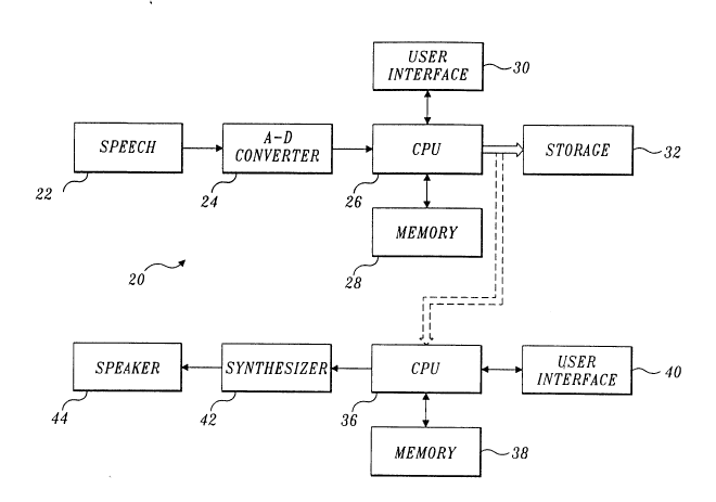
are shown generaUy in FIGURE 2 at reference numeral 20. A block 22 .~pl~r.t~
either speech uttered in real time or a recorded voc~li7~tirn Thus, a person
s~kin~ into a miclophone may p~ducc the speech in~ ~d in block 22, or
allelllati~ely, the words spoken by the speaker may be stored on semi-p~llllancnt
15 media, such as on magn.o.ti~ tape. Whether prudu~ by a micluphone or by
playback from a storage device (neither shown), the analog signal pluduccd is
applied to an analog-to-digital (A-D) con~e~t~ 24, which changes the analog signal
l~plcse.~ g human speech to a digital format. Analog-to-digital converter 24 maycompri~ any suitable col~ ;al in~ld~ circuit A-D converter capable of
20 providing eight or more bits of digital resolvffo~ through rapid conversion of an
analog signal.
A digital signal ploduced by A-D c~u~tl r 24 is fed to an input port of a
central proc~or unit (CPU) 26. CPU 26 is plVg~ to carry out the steps of
the present method, which include the both the initial training session and analysis
25 of subse~ucnt speech from block22, as dcs~-;bcd in greater detail below. The
plOgl~ull that controls CPU 26 is stored in a u-c l~l~ 28, oom~risin~ for e~cample,
a ma~n~ti~ media hard drive or read only 1.~,.~l~ (ROM), neither of which is
s~p~dt~ly shown. Also included in Ill.,.llG ~ 28 is random access UIC.ll~
for le,.u~l~ily storing variables and other data used in the training and analysis.
30 A user ;n~j~. r.~r 30, c4l~ ;r~ a ~l~d and display, is connP.t~ to CPU 26,
allowing user in~ r and ll.or~;l~..;r~g of the steps imr'~mPn'~d in ploce-
~
the speech from block 22.
Data p~Ju~ during the initial training session through analysis of speechare cGn~c~d to a digital format and stored in a storage device 32, CQ~ a
35 hard drive, floppy disk, or other non~ol~lilc storage media. For a~soqu~l~
p~c~s~;nE speech that is to be srthe~i7~ CPU 26 carries out a pe~plual linear
US~VA15356UDOC
2~7~4 1 8
.
plodic~ (PLP) analysis of the speech to d~ -;ne several cepstral coeffi~i~nts,
Cl . . . Cn that compri~e the speaker-inde~ndçnt data. In the prefe.l~d
embodiment, only five cepstral co~ffi~i~ont~ are l~uilod for each s~ of the
speaker-in~e~ndent data used to synth~-~i7e speeich (and in ~training~ the speaker-
5 dependent model).
In ad~itinn~ CPU 26 is programmed to perform a formant analysis, whichis used to de~ ..h-~ a plurality of foll..anls Fl th~ough Fn and col~,~nding
bandwidths Bl through Bn. The formant analysis produces data used in
fol~ A~ a speaker~ep~ndent model. The formant and bandwidth data for a
10 given segment of spxch differ from one speaker to another, de.~nding upon theshape of the vocal tract and various other speaker-dependçnt physiological
parameters. During the training phase of the process, CPU 26 derives mllltip!e
- gl~ssi~e spea~er-d~pend~nt ll,appings of the ce~stTal coeffi~nts of the speechseglner,ts spoken during the training e~ercise, to the coll~nding foll,lanls and15 bandwidths Fi and Bi for each s~,..ent of speech. The speaker-de~pendçn~ model
resulting from Illdpping the cepstral coeffi~i~ntc to the follllants and bandwidths for
each segment of speech is stored in storage device 32 for later use.
Alt~ ..~til._ly, instead of storing this speaker~e~endent model, the data
co...~s. ;c;~l~ the model can be t~nc ~ d to a remote CPU 36. either prior to the
need to s~,ltl,e~ speech, or in real time. Once remote CPU 36 has stored the
speaker~ de~t model required to map between the speaker-in~ep~nd~n~
cepst~al c4err- :t ~1~ and the fo~ ntc and bandwidths ,~l~ t;-~g the speech of ap~licular speaker, it can apply the model data to ~ubs~ucn~ly tr~nsmined cepst~al
coPffi~Pn1c to ~pl~luce any speech of that sa ne spea~er.
The speaker-de~ndent model data are applied to the speaker-ind~nde~
cepst~al coeffi~ pn~c for each 5~ of speech that is !-~nc---;l~d from CPU 26 to
CPU 36 to Icplu.luce the synth~pci7~d speech, by .-~;n~ the cepstral ~rr~:e~c
to c~llr,~n~ E follllallb and bandwidths that are used to drive a a~ h~ 42.
A user interface 40 is c~nn~c~ to remote CPU 36 and preferably inClud~ps a
~ and display for en~Pring irls~luctions that control the synthesis process and
a display for . onilr~;n~ its proglcssion. S~ P~ 42 preferably COIll~li~s a
Klsyn88T~ cascade/parallel fc,l",ant srth~pci7~r~ which is a co,l,bin~lio" sonw~c
and h~J~ package available from Scn~ 5 Corporation, Cambridge,
M~c~nhns, 11~ However, virtua~y any synthpci7pr suitable for synthPci7in~ human
speech from LPC formant and bandwidth data can be used for this purpose.
SrthPci7pr 42 drives a col~ ;onq1 1ouAc~lrpr 44 to produce the srthP-si7~Pd
-- 2~74~1~
spe_ch. Loudcp~P-A~Pr 44 may alt_rnativdy compris_ a tPIP~h~ne ~e.~er or may
be r~plac~d by a l~co~ing device to record the srthPci7~pd speech.
Remote CPU 36 can also be controlled to apply a speaker-depPnd~Pnt model
mapping for a dil~nt speaker to the speaker-indcpe~ n~ cepstral coeffi~iPntc
- S tlAn~ d from C~U 26, so that the speech of one speaker is synthPci7~pd to sound
like that of a different speaker. For e~cample, speaker-depPndent model data for a
female speaker can be applied to the ~.Ahc~..;t~ed cepstral coPfficiPntc for each
e.g..-f-n~ of speech ~from a male speaker, causing synthPci7pr 42 to produce
synthPci7pd spe_ch, which on lou~c~Al~er 44, sounds like a female speaker
10 cpeAhng the words originally uttered by the male spea~r. -CPU 36 can also
modify the speaker-dependen~ model in other ways to çnhAnc~, or otherwise
change the sound of the synth~Psi7~d speech produced by loudcp~l~ 44.
One of the primary advantages of the technique imrlcmPnt~Pd by the
app~atus in FIGURE 1 is the reduced quantity of data that must be stored and/or
15 tl .nc .;~led to syn~h-p-ci7Lp~ speech. Only the speaker-dependent model data and the
cepstral co~pfficipntc for each ,.,c~sc-~e se.~ t of speech must be stored or
ll~n~ ..;t~ d to synth~Pci7e sp_ech, thereby reducing the number of byt_s of data that
need be stored by storage device 32, or tr~nsmittPd to remote CPU 36.
As noted above, the training steps implem-Pnted by CPU 26 initially
20 de~nnin-P the ,.~pping of cepstral coeffi~ientc for each c~-.-cnl of speech to their
col~ on~ fo.-.-ant~ and bandwidths to define how s-lbs~u~n~ speaker-
inde~.-d.~ cepstral coeffirientc should be mapped to p,oduce synth~oci7~d speech.
In FIGURE 3, a flow chart 50 shows the steps imp'~m~nted by CPU 26 in this
~aining p~C~ul~; and the steps later used to derive the speaker-independent
25 ceps~al co~ffirientc for syn~h~pci7inp- speech. Flow chart 50 starts at a block 52.
In a block 54, the analog values of the speech are ~iigiti7ed for input to a block 56.
In block56, a pl~'d~f;nPd time inteIval of appr~sim-tPly 20millic.~nds in the
~ ,f~l~d emho~liment defines a single 5~ n~ of speech that is analy_ed
accol~ng to the following steps. Two procedurec are perfor ned on each ligiti7~d
30 e~...ei-~ of speech, as indica~d in flow chart 50 by the parallel bl~r.ches to which
block 56 c~nn~
In a blockS8, a sub~uline is called that pelroll,ls formant analysis to
de~ -e the Fl through Fn formants and their coll~ponding bandwidths, Bl
through Bn for each seg..~e~ of speech p~ d. The details of the s~brouline
35 used to p~l~ol~ll the forrnant analysis are shown in FIGURE 5 in a flow chart 60.
Flow chart 60 begins at a block 62 and pl~eeds to a block 64, wherein CPU 26
~A~DO~
207~4~8
dct~ nPs the linear pre~licttl~n c~ffi~P~nts for the cuITent S~g~P~I of speech
being plvcess~. Linear predictive analysis of digital speoch signals is well known
in the art. For e rle, J. Makhoul des~ribed the technique in a paper entitled
~Spectral Linear Pre~lictinn: Properties and ~rpli~tiol-c,~ TFF.F TlAr~C~ -n
S ASSP-23, 1975, pp. 283-296. Simil~ly~ in U.S. Patent ~o. 4,882,758 (IJekawa
et al.), an improved method for e~ g formant fiequu cies is tli~rlo~d and
col,lp~c;d to the more coll~ ;Qnql linear predictive analysis method.
In block 64, CPU 26 p,~ce~5 the digital speech se.~ n~ by applying a
pr~ e,llphasis and then using a window with an antocr~ aLion c~ tion to obtain
linear prediction coeffici~ntc by the Durbin method. The Durbin method is also
well known in the art, and is de~ribed by L. R. Rabiner and R. W. Schafer in
Digital Processing of Speech si~n~lc~ a Prentic~Hall pub~ t~ ) pp. 411~13.
In a block 66, a col~c~n~ Zo is selected for an initial value as a root Zi- In
a block 68, CPU 26 det~ll"ines a value of A(z) from the following equation:
A~= ~a~ Z~ (aO = ~
Ic. O (1)
where ak are linear pre~ictir~n c~ffi~ n~c~ kl;l;Qn, the CPU det~t~nin~s the
deaivative A'(Zj) of this fil~tir~n. A d~ic;~n bloclc70 then d~lll~in~s if the
~t sol~t~ value of A(Zi)/A'(Zj) is less than a spe~tfi~d tolerance threshold value K.
If not, a block 72 assigns a new ~ralue to Zi. as shown therein. The flow chart
20 then retums to block 68 for n~le~l.~n~ n of a new value for the function A(Zi)
and its derivative. As this iterative loop cont;.~ s, it eventually reaches a point
where an arrllll~ti~e result from deçicion block70 leads to a block74, which
assigns Zi and its comple~ ~onjugat~ Zi'' as roots of tbe function A(z). A block 76
then divides the function A(z) by the quadratic eA~,l~ion of Zi and its comple~
25 conjugate, as shown therein.
A d~ision block78 d~,.,ines whether Zi is a zero-order root of the
funcdon A(Z) and if not, loops back to block 64 to repeat the process until a zero
order value for tbe runction A(Z3 is obt~-nPd Once an afri~ ati~e result from
derici~-t block 78 occurs, a block 80 d~t~ll~nes the coll~rding f~ ul~ Fk for
30 all roots of the equadon as defined by:
FK = (f~ /2~)tan~~m~j)/Re(Z;)] (2)
Similarly, a block 82 defines the bandwidth ~ll~s~nding to the fo~ b for all
the roots of the function as follows:
-9- 207~14~8
BK =(~ )ln¦ 2; I (3)
A block 84 then sets all roots with Bk less than a çonctqnt threshold T equal
to fol.l~nts Fi having CO~ ondin~ bandwidths Bi. A block 86 then returns from
the subroutine to the main program impkPmPntPd in flow chart 50.
-5 --Following a return from the sub~ouline called in block S8 of FIGURE 3, a
block 90 stores the formqntc Fl through FN and corrcspon~ing bandwidths B
through BN in .-c,..~ 28 (FIGURE 2).
The other branch of flow chart S0 following block 56 in FIGURE 3 leads to
a block 92 that calls a subn)llline to perform PLP analysis of the .ligiti7~ speech
10 s~g~pnl to det~l.-,inc its cG~ onding cepstral coeffi~pntc The sublolltinc called
by block 92 is illu;~llatcd in FIGURE 6 by a flow chart 94.
Flow chart94 begins at a block96 and p~xeeds to a block98, which
pcl~ln~s a fast Fourier ~ansform of the .ligiti7~d speech egm~n~ ing out
the f st Fourier tldnsful,.., each speech s~g...-~' is ~.c;ghtod by a ~mming
15 window, which is a finite duration window rep,~ntod by the following equation:
U~n) = QS4 + Q46cos~n/ ~- ~] (4)
where T, the duration of the window, is typically about 20 milli$e~ntl5 The
Fourier transform pelru~",ed in block 98 transforrns the speech sP~mPnt weightedby the ~mming window into the frequency domain. In this step, the real and
20 i~. ag;n ~ co-,-poncnts of the resulting speech 5pC~,11~ll are squared and added
together, pr~ducing a short-terrn power s~ecl-ul-, P(~),which can be l~)~nt~d as
follows:
P(a~) = Re~ 2 + Im~;(63)~2 (5)
Typically, for a 10 KHz ~mrling r~ucnc~, a 256-point fast Fourier ll~lafollll is25 applied to l.dns~,.. 200 speech ~mrles (from the 20-milli~ond window that wasapplied to obtain the se~ nt), with the ,~,..ain;Qg 56 points padded by zero-valued
~:~m~
In a block 100, critical band integ,d~on and rec~mrling is pclrol-..ed,
during which the short-terrn power a~llulll P(~) is wa~ped along its ~l~U~ICy
30 access ~ into the Bark frequency n as follows:
USU~DOC
2 Q 7 ~
._
-( 2 ~5'
120~ 120~ (6)
wherein ~ is the angular frequency in radians per second, resulting in a Bark-Hztransformation. The resulting warped power s~ -- is then convolved with the
power s~ u--l of the simul~ted critical band mqCl~in~ curve ~ cept for the
S particular shape of the critical-band curve, this step is similar to spectral proc~g
in mel cepstral analysis. The critical band curve is defined as follows:
0 forQ <-13
102-5~ +0-5) for -L3 <n < -o.s
~(Q)=~ 1 for -L5 <Q <Q5
lo-l o~-o SJ for ~5 <Q ~2.5
0 forQ >2.5 ~7~
The piece-wise shape of the simnlqt~d critical-band mqCl~ing curve is an
appro~imqtion to an asymmPtric n ~c~ g curve. Thc intent of this step is to
10 provide an app~o,i---ation (qlthough so---~..hat crude) of an auditory filter based on
the pl.~si~on that the shape of auditory filters is app~ q-tply collC~n- OD the
Bark scale and that thc filter skirts are gcnerally tl unc~d at ~OdB.
Convolution of ~(w) with (the evcn 5~..,...~h;r and pPlio~lic function) P(c-~)
yields sarnples of the critical-band power a~llU
2.5
e(nj)= P(n-Qj)~(n)
~.-1.3 (8)
This convolution cienific~q-ntly reduce the spectral res~llltion of e(n) in
co...~q.;con with the original P(~), allowing for the down-sqmrlin~ of e(fl~. Inthe preferred e.l~ , e(n) is sqn~r!Pd at aWl.,~ y one-Bark intervals.
20 The e~act value of the sqmrline interval is cho~n so that an integral number of
spectral sarnples covers the entire analysis band. Typically, for a bandwidth of
USWA~WDOC
-11- 2~7441~
5 KHz, co~ ~n~ling to 16.9-Bark, 18 spectIal arnples of e(n3 are used,
providing 0.994-Bark steps.
In a block 102, a logarithm of the co."~Jled critical-band ;~pecllulll iS
~,l,ned, and any convolutive cQficl~htc appear as additive C~fiC~ lc in- the
5 log~Tithm
A block 104 applies an equal-loudness l~nse curve to prc e-..ph~ e
each of the s~g....-n~, where the equal-loudness curve is lepl~nt~d as follows:
-[n(~ )e[n(~D)] (9)
In this equation, the function E(~) is an appro~im~tion to the hum~n sensitivity to
10 sounds at different frequencies and simulates the unequal sensitivity of hearing at
about the 40dB level. Under the e oon~litionc~ th~ function is defined as follows:
2 + 6~o6)2(~l,2 + 0.3&~109) (10)
The curve appr~im~tPs a transfer function for a filter having asymptotes of 12dB15 per octave between O and 400Hz, OdB per octave between 400Hz and 1,200Hz,
6dB per octave belween 1,200Hz and 3,100Hz, and zero dB per octave ~t~een
3,100Hz and the Nyquist Lc~ue~ (lOKHz in the pltf~ d e k)~ nl). In
applin~tinns ~equiring a higher Nyquist L~u~.~, an ad~litinn~l term can be addedto the pf~ding e,.pl~s;on. The values of the first (zero Barlc) and the last
20 samples are made equal to the values of their nearest rl~ighb~rs to ensure that the
function resulting from the a~plic~irn of the equal louAnPss ~s~nse curve beginsand ends with two equal-valued ~q-np1~ s
In a block 106, a power-law of hearing function approsimqtion is
p~ r~ ed, which involves a cubic-root q-~-pl;lud~ ~"l~l~ion of the 5pC~ ll'UIll,25 defined as follows:
_ -12- ~07~418
~(n)=_(Qp.33 (11)
This cGI~.plession is an appro~ ;on that Sim~ tPc the nonlinear relation betweenthe inter,sil~ of sound and its pe~ eA loudness. In combination, the equal-
loudness pre~mph~cic of block 104 and the power law of hearing function applied
5 in block 106 reduce the spectral-~mrli~lde variation of the critical-band Sp~tlu
to produce a relatively low model order.
A block 108 provides for det~ ;n;ng an inverse lOg~ n~ ~l.e., detenr~ines
an e~ponential function) of the cc Illpl~s~d log critical-band ~JeCI.rUlll. The
resulting function appro~cimate_ a relatively auditory Sp~tlUIll.
A block 110 del~lnlnes an inverse discrete Fourier transform of the
auditory ~ll ulll ~(n). Preferably, a 34-point inverse discrete Fourier transform
is used. The inverse discrete Fourier tr~ncf( nn is a better choice than the fast
Fourier lldr.srollll in this case, because only a few a~-~oc~ lation values are
required in the subse~uent analysis.
In linear predictive analysis, a set of c;~pffici~p-ntc that will ,~.ini.. ;~ a mean-
squared prediction error over a short s~ n~ of speech w~.efolll~ is d~t- .~...n~A
One way to de~,lnine such a set of c~pffil~ipntc is referred to as the aulocoll~lation
method of linear preAicti-n This appluach provides a set of linear equations that
relate all~oll~la~ion coeffinipntc of the signal ~ g the plOC~ speech
20 ~P~1n- nS with the preAictinn COf fl~c ~ C of the au~~ model. The resulting
set of e~luations can be efficiPntly solved to yield the pl~ t~r ~-A---- ~ The
inverse Fourier transfor n of a non-negati~.e s~tlulll-like function resulting from
the pl~ceding steps can be ir.t~l~ as the au~ll~lation function, and an
ap~luyliale aulo~gl~s;,.~e model of such a sp~:llul~. can be found. In the
25 pl. fe.led embodiment of the present nle-hod the equations for c~lj.ng out this
solution apply Durbin's rccul~e p~luuc, as in-li~t~ in a block 112. This
US~A15356~0C
-13- 2Q74~18
pr~lllle is relatively effieient for solving specific linear equations of the
aulol~;l. s~i~e process.
Finally, in a block 114, a recursive co~ ,u~lion is applied to determine the
-- cepstral coefficients from the aulol.glcss;~e. coeffi~iPnt~ of the resulting all-pole
5 model.
Lf the overall LPC system has a transfer function H~z) with an impulse
les;)onse h(n) and a colllple~ cep;,llul l h(n), then h(n) can be obtained from the
recurslon:
h(n) = an ~ )fi(k)a,~t 1 ~ n
~ n (12)
where
~z) = ~,h(~z-~ = G
l-~ ~z
(13)
(as shown by L. R. Rabiner and R. W. Schafer in D;~ital Processing of S~eech
Signals, a Prentice-Hall public~tion, page 442.) The co---ple~ Cep~llUIII cited in
15 this lef~ce is equivalent to the ceps~al xffi~entc Cl through Cs.
After block 114 produces the cepstral c~ffi~Pntc a block 116 returns to
flow chart 50 in FIGURE 3. Thc~ r, a block 120 provides for storing the
cepstral c~ffi~ients Cl through Cs in non~olalile llle.llul~. Following blocks 90
or 120, a d~P~n block 122 det~.--;n~s if the last seE.~cnt of speech has becn
20 pfOCeSS~d, and if not, returns to blocl~ S6 in FIGURE 3.
- After all se~ of spe_ch have been p~ces~ a block 124 provides for
deriving mnltiple regl~sai~e. spealcer-de~pndpnt mappings from the c~ps~al
coPffi-~iPntc Ci using the coll~s~n~ling fo.lllants Fi and bandwidths Bi. The
Illapping process is glapLcally illu~la~ in FIGI~RE 7 generally at rc;fc..,~ce
25 numeral 170, where five cepstral coeffi~ipntc 176 and a bias value 178 are linearly
US~IA\53~1WIXIC
20~418
c~",binfd to p~uducc five fol"~ant and collesponding bandwidths 180 according tothe following rel~t~ chi?:
e, =a,O+~a,jC,j
''~ (14)
where ei are cle-"f-~lC ~ ~n~ g the res~li~ formants and their bandwidths
(i = 1 through 10, c4ll~ponding to Fl through F5 and B1 through BS, in
succeCci- n), aio is the bias value, and aij are weightin~ factors for the j-th cepstral
coeffinient and the i-th element (fol-l-ant or bandwidth) that are applied to the
ceps~al c~pffici~pn~c Cij. Mapping of the c_pstral coeffil~ifntc and bias value
c~ onds to a linear function that esrimqt~s the re1~tionchir between the
formants (and their coll~onding bandwidths) and the cepstral coeffiniPntc.
The linear ç~g~ssion analysis p~.-o~-"ed in this step is diccucse~ in detail in
An Int.~luc~ion to Linear Re~ression and Correlation. by Allen L. Edwards
(W. H. Freeman & Co., 1976), ch. 3. Thus, for each sc~.msf nt of speech, linear
regression analysis is applied to map the cepstral cofffirifntc 176 and bias
lS value 178 into the fol-ants and bandwidths 180. The mapping data resulting from
this p[~]UlC are stored for sul)se~ufnt use, or i~ f ~ fly used with speaker-
i~ep~nde nt cepst~al coefficif ntc tO Sy~thf~ci7~ speech, as e~pl~ine~d in greater detail
below. A block 128 ends this first training portion of the pn~cedu.e re~.~ d ford~ ~_loping the spe~aker-deppn~pnt modd for --apping of speaker-indepPnd-Pnt
cepstral c4pffiripntc into co,l~s~nding folll,ants and bandwidths.
Tun~ing now to FIGURE 4, the speal~er~cp~nd~f--t model defined by
~;ng data developed from the haining p~X4JUlC implfA ~f nt~d by the steps of
flow chartS0 can later be applied to speaker-inde~dc~l data to syn~h-Pci7P
vo~ nS by that same speaker, as briefly no~ above. Alterna~vely, the
speaker-independ~P-nt data (l~ntod by cepstral c~Pffi~ientc) of one speaker can
be mo~1ifi~pd by the model data of a different speaker to produce syn~hpci7~pd speech
2Q744~8
co~ ~nding to the voc~ tion of the different speaker. Steps required for
carrying out either of these ~n~-;os are illustrated in a flow chart 140 in
FIGURE 4, starting at a block 142.
In a block 143,-signals l~>r~nt;ilg the analog speech of an individual
S (from block 22 in FIGURE 2) are applied to an A-D com.c~t~, producing
collcs~ondJng digital signals that are processed one ~ 1 at a time. Digital
signals are input to CPU 36 in a block 144. A bloclc 146 caDs a sul)rouline to
p~lÇullll PLP analysis of the signal to determine the cepst al coeffirientc for the
speech segmrnt, as e~ in~d above with reference to flow chart 94 in FIGURE 6.
10 This subl.)uline returns the cepstral coeffiri~ntc for each sc~ nt of speech, which
are ~ltern~tively either stored for later use in a bloclc 148, or n~ ...;ll~, for
e~ by t~lF,PhOn~ line, to a remote location for use in syntheci~n~ the speech
ed by the speaker-inde~endent cepstral co~ffirientc TPncmic~ n of the
cepstral c4effiri~ntc is provided in a block 150.
In a block 152, the speaker~ependent model lei,l~n~i by the mapping
data previously de~eloped during the training pr~ced~e is applied to the cepstral
c~effiri~ntc which have been stored in block 148 or ll~n~m;lhd in block 150, to
develop the fol",an~ Fl through Fn and col~nding bandwidths Bl through Bn
needed to synthesize that cJ~,..f 1 of speech. As noted above, the linear
20 combination of the cepst~al c~ffi<ientc to produce the fol..~ats and bandwidth
data in block 152 is graphicaUy il;.~ in FIGURE 7.
A block 154 uses the fo....~ and bandwidths developed in block 152 to
p~oduce a coll.~l.on~ g synth~oci7~d s~g---~ of speech, and a block 156 stores the
~lieiti7~ gment of speech. A de~iciQn block 158 det~.. nPs if the last segJn~nt
25 of speech has been ~lvc~sed, and if not, returns to block 144 to input the ne~t
speech s~gmPnt for PLP analysis. However, if the las~ segm.ont of speech has been
plV~, a block 160 provide for digital-to-~n~log (I)-A) con~ on of the
,
-16- 2 ~ 1 8
digital signals. Referring back to FIGURE2, block 160 produces the analog
signal used to drive lou-lsp~l~Pr 44, producing an auditory ~ ,onse syntheti~llyreproducing the speech of either the original speaker or speech sounding like
another person, depen~lin~ upon whether the original speaker's model (Ill~l~)pU~g
S data) or the other person's model is used in bloclc 152 to map the cepstral
coefficientc into corresponding foll,lants and bandwidths. A block 162 tf-..,;n~s
flow chart 140 in FIGURE 4.
E~penmPnt~ have shown that there is a relatively high correlation betwecn
the estim~Pd formants and bandwidths used to synthPsi7P speech in the present
10 invention and the foll"al~ts and bandwidths dete.,l~ined by conventional LPC
analysis of the original speech s~ l Table l, below, shows co~ tions
h-etween the true and model-predicted form of these pq-ramPtPrS~ the root mean
square (RMS) error of the pre~lintion~ and the mq~imlJm prediction error. For
com~ri~on, values from the 10th order LPC formant estimqtit~n are shown in
15 parenthp~ps The RMS error of the PLP-based formant frequency prediction is
larger than the LPC estimqtion RMS error. LPC e~hibits occq~ionql gross errors
in the estim-q-ti~n of lower fo,lnants, which show in larger values of the mq~imllm
LPC error. In fact, formant bandwidths are far better predicted by the PLP-basedto;l~ u~.
TABLE 1
FORM~NT AND BANDWIDTH COMPARISONS
PARAM. Fl F2 F3 F4 F5
CORR. 0.94(0.98) 0.98(0.99) 0.91(0.98) 0.64(0.98) 0.86(0.99) ~
RMS[Hz]-23.6(15.5) 48.1(37.0) 48.2(21.2) 46.1(12.6) 52.4(13.1)
MAX[Hz] 131(434) 344(2170) 190(1179) 190(610) 220(130)
USWAID5LUI~O~
2~74418
Bl B2 B3 B4 B5
CORR. 0.86(0.05) 0.92(0.17) 0.96(0.43)0.64(0.24) 0.86(0.33)
RMS~Hz] 2.2(45) 1.6(35) 4.1(37)4.1(50) 5.5(52)
-- MAX[Hz] 29.3(3707) C.23(205) 32.0(189)18.0(119) 22-.0(354)
A cignifir~nt advantage of the present t~chnique for srthesi7ing speech is
the ability to synth~ci7e a different speaker's speech using the cepstral coe-ffl~i~o-ntc
developed from low-order PLP analysis, which are generally speaker-indep~n~nt
5 To evaluate the potential for voice mo~ifi~ti-n the vocal tract area filn~tinnc for a
male voicing three vowels lil, /al, and lul were modified by scaling down the
length of the ph~rng~l cavity by 2 cm and by linearly scaling each ph~ng~l
area by a conct~nt This conct~nt was chosen for each vowel by a simple search sothat the dirr~ences b~t~cen the log of a male and a female-lilce PLP spectra are10 minimi7~l It has been observed that to achieve similar PLP spectra for both the
longer and the shorter vocal tracts, the pha~ 2~al cavity for the female-like tracts
need to be slightly e~nde~
FIGURES 8A through 8C show the vocal tract functionc for the three
Russian vowels lil, lal, and lul, using solid lines to lepr~nt the male vocal tract
15 and dashed lines to l~,l~nt the cimlll~ted female-like vocal tract. Thus, fore~cample, solid lines 192, 196, and 200 l. ~l~nt the vocal tract configuration for a
male, ~ he.~s dashed lines 190, 194, and 198 l~l~,lt the cim~ d vocal tract
voicing for a female.
Both the original and modified vocal tract fun~tionc were used to g~n~ate
20 vowel spaces. The training pr~ced~ de~rihed above wa used to obtain speaker-
dependent models, one for the male and one for the cim~ t~ female-like vowels.
PLP vectors (cepstral co~fficients) derived from male speech were used with a
female~ model, yielding predicted fo~ t~ a shown in FIGURE9A.
usw~ ns6u~c ,
-18- 2@7~
Similarly, PLP vectors derived from fernale speech were used with the rnale
l~l~a,-~e models to yield predicted fol~l~anb depicted in FIGI~RE 9B. In
FIGURE 9A, bound~ s of the originql male vowel a~ace are ind;c~ed by a solid
line 202, while bolln~ries of the original female -pace are in~li~t~d by a dashed
S line 204. Similarly, in FIGURE 9B, bol~nd~ ;es of the original female vowel space
are in~ qt~d by a solid line 206, and boundqri~s of the original m. le vowel space
are in(licqt~d by a dashed line 208. Based on a C4~ of the Fl and F2
formants for the original and the predicted models, both male and female, it is
evident that the range of predicted formant fic4uu~cies is det~..-l,ned by the given
10 rcgression model, rather than by the speech signals from which the PLP vectors
a re derived.
Further verifirqti~n of the te hniquc for srth~-ci7irlg the speech of a
particular speaker in acco,dance w,ith the pre ent i,~erllion was pluvidcd by the
following e~ i...ent The regression speaker-dependent model for a particular
15 speaker was derived from four all-voiced ~nt~ es ~We all learn a yellow line
roar;~ ~You are a yellow yo-yo;~ ~We are nine very young women;~ and ~Hello,
how are you?~ each uttered by a male speaker. The first five cepstral coeffi~entc
(log energy e-cl.-d~) from the fifth order PLP analys~c of the first ul~ n~e, ~Iowe you a yellow yo-yo,~ together with the l~g~si~e model derived from training
20 with the four r ntenC~s were used in pl~lictillg fo,-,~ls of the test ut~ -, n~ as
shown in FIGURE 10B.
An ~s~ d formant llaj~;t~ ~plC~lt~ by pole of a 10th order LPC
analysis for the same senten~ I owe you a yellow yo-yo,~ uttered by a male
speaker are shown in FIGURE 10A. Co~ . ;ng the pl~di t~d formant tr~ torips
25 of FIGURE 10B with the ~stim~ formant ll~je.~..es l~ by poles of the
10th order LPC analysis shown in FIGURE 10A, it is clear that the first forrnant is
predicted le~ ty well. On the seoond formant n~iectul~, the largest dirr~l~nce
USWA~D54~DOC
-19-
`~ 2~74~18
is in /oh/ of ~owe ....,~ where the predicted second for nant frequency is about50% higher than the LPC estimqtf~d one. Furthermore, the predicted L~uenc;~s
of the ljls in ~you~ and ~yo-yo,~ and of /el and lul in ~yellow~ are 15-20% lower
than the LPC estimq~ted ones. The pre~lic-q-~fd third order~tldjf~oly is again
S reasonably close to the LPC estimq-t~ed lldjceto,~. The LPC esrimqtfd fourth and
fifth fol,l,ant~ are generally un~ ablc and co~ zl;ng them to the pl~iiCt~
trajeclolif~s is of little value.
A similar experimfnr was done to detf~ ne whether synthetic speech can
yield useful speaker~ependfnt modds. In this case, speaker-df~endent. models
10 derived from synthetic speech vowels were used, to produce a male leg~
model for the same sentf n C~ The trajf~;~olif s of the fol,l,anls predicted using the
male l~less;~/f model in the first five cepst~l coefficients from the fifth order
PLP analysis of the sentence ~I owe you a yellow yo-yo~ uttered by a male speaker
were then CGIllpal~,d to the tl~jf~to.;es of forrnqntc pr~dictod using the female
lS r~6ressi~e model (also derived &om the synthetic vowel-like ~q ,'~s) in the first
five cepstral coefficients from the fifith order PLP analysis of the same 5~n~fnrc,
uttered by the male speaker.
Within the 0 through 5 KHz rl~u~ band of interest, the male l~6l~i~.
model yields five fo"lla~lt~, while the female-like model yields only four. By
20 conlpqri~n of FIGURES llA and llB, it is a~ nt that the formant n~ie~ rs
for both genders are app~u~ fly the same. The fi~uf~le~ span of the female
second formant ~ jec~ is visibly larger than thc fr~u~l~ span of the male
second formant lldjf~lu,~, almost ~oin~ ~l;ng with the third male Çolllldn~5 in
e~ctreme front semi-vowels, such as the ljls in ~yo-yo~ and being rather close to the
25 male second formants in the ,uunded /u/ of ~you.~ The male third formant
t,dje~ is very similar to the female third formant ~ o,~, e~ccept for
a~p~ y a 400 Hz c~n~tqnt do. ~lw~.l frequency shift. However, the male
USWA~DOC
-2~ 2Q7~4i~
fourth formant trajectory bears almost no simil~rity to any of the female formant
tra3e.to.;~s~ FinaUy, the fifth formant trajectory for the male is quite similar to the
female fourth formant trajectory.
Although the preferred embodiment uses PLP analysis to de~~ e a
5 speaker-dep~ndpnt model for a par~cular speaker during the training process and
for producing the spea~er-indepe~ndf nl cepstral coefficipntc that are used with that
or another speaker's model for speech synthesis, it should be a~ nt that other
speech p.~ce-c~ g techniques might be used for this purpose. These and other
mlxlific~ti- nc and changes that will be app~nt to those of ordin~ ~ sl~U in this art
10 faU within the scope of the claims that foUow. While the preferred embodiment of
the invention has been illu~ ed and described, it wiU be appreciated that such
changes carl be made therein without departing from the spirit and scope of the
invention defined by these claims.
USW~6UDOC