Note: Descriptions are shown in the official language in which they were submitted.
~37-~L~7~
~glO2
-- 1 --
SPECIFICATION
HYDRAULIC TENSIONING SYSTB IN PRSSENGER ONVEYORS
Field of the Invention
This invention generally relates to tha art of
passenger conveyors such as escalators or the like, and,
particularly, to a hydraulic tensioning system for a
turnaround track assembly of a passenger conveyor.
Backaround of the Invention
A passenger conveyor t~pically includes a series
of passenger platform~ or steps which are driven in an
endless path between horizontally spaced landings. The
passenger conveyor includes a main body frame supported by
the ~loors or other support structures of a building, for
instance, and conventionally has ~rack means for the
passenger platforms to guide the platforms along a path
between the landings. Typically, the track mean include
a ~upport track for support rollers mounted to th2 respec-
tive passenger platforms, and, in some instances, guide
rollers movable along a guide krack.
For instance, in an e~calator-type passenger
conveyor, an endles~ series o~ steps are moved ~rom one
landing to another to convey passengers. The steps are
interconnected by means of a sprocket chain, sometimes
called a running gsar chain. U~ually, such a chain i~ used
on each side o~ the escalator. In addition, each ~tep is
provided with at least one support roller on each side
thereof, associated with the running gear chain, along with
a trailer roller. Guide means are provided at each end o~
the e~calator for guiding the rollars around the bends of
the endless conveyor means. The guida mean~ usually are
provided in the form o~ a turnaround track ass~mbly. The
track assembly includ~s pairs of lnner and outer curved
~7~
N9102
- 2 -
tracks for the suppor~ rollers and the trailer rollers to
rotate around the bends at the ends of the escalator.
It is typical in escalator-type passenger convey-
ors to provide a chain tensioning system at one end of the
conveyor system, such as beneath the lower landing. The~e
tensioning systems sometimes are termed "step band tension~
ing systems". Heretofore, a typical escalator step b~nd
tensioning system included a compres~ion spriny mechanism
on each side of the conveyor or operatively associated with
each side chain~ The tensioning typically was mechanical
in nature, such as with a threaded rod associated with the
compression spriny. In order to equalize ten~ion on
oppo~ite sides of the conveyor, i.e., to equalize the
respective tension~ on the side chains, tape or ruler
measurements were used to estimate the tension setting.
Such settings actually are approximate, at best, and are
susceptible to certain variances, such as different com-
pression spring rates, and are susceptibla to other mis-
adjustments due to wear as well as maintenance human error.
This invention is directed to providing a hydrau-
lic tensioning system designed to automatically equalize
the chain tension on opposite sides o~ the conveyor or
escalator.
Summa~y of the Invention
An object~ therefore, of the invention is to
provid~ a new and improved ten~ioning sy~tem for a turn-
around track assembly of a passenger conveyor.
As disclosed herein, a pa~senger conveyor i~
illustrated in the form of an escalator which include~ a
series of steps or passenger plat~orms supported on and
movable along a frame which include~ side support tracks
for chain driven support roller~ mounted on the platforms.
A turnaround track as~embly is located at an end o~ th~
conveyor, with track mean~ on each side of the moving
~9102
-- 3 --
plat~orms. The turnaround track assembly is movably
mounted relative to the frame and side ~upport tracks.
The invention contemplates a chain tensioning
system operatively associated between the turnaround track
S assembly and the ~rame. The tensioning system includes a
hydraulic tensioning device interconnected between the
turnaround track assembly and the frame on each side
thereof. A source of pressurized hydraulic fluid commu~i-
cates with the tensioning devices. Means are provided for
hydraulically interconnecting the teneioning d~vices to
equalize tensioning between the side~ of the turnaround
track assembly.
As disclosed herein, the source of pre~surized
hydraulic fluid ls hydraulically connected to an accumula-
tor which, in turn, is hydraulically connected to the side
hydraulic tensioning devices, thereby equalizing the
pressure therebetween. In the preferred embodiment, the
hydraulic tensioning devices comprise piston and cylinder
devices.
In the illustrated e~bodiment of the invention,
the hydraulic devices are interconnQcted between push
members fixed to the frame and slide members movably
mounted on the frame and ~ixed to the turnaround track
assembly. The slide members are provided in the form of
slider plates having opposite edges supported by roller
means.
Other objects, features and advantage~ of the
invention will be apparent from the following detailed
description taken in connection with the accompanying
drawings.
Brief Description O~ The Drawin~s
The features of this invention which are beli~v~d
to be novel ar~ ~et ~orth with particularity in the
appended claims. The invention, together with it8 object~
and the advantages thereof, may be best understood by
- M9102
-- 4 --
reference to th~ following description taken in conjunction
with the accompanying drawings in which like reference
numerals identlfy like elements in th~ igures and in
which:
FIGURE 1 is a somewhat schematic illustration of
a typical escalator construction, with the hydrau~ic
tensioning system of the invention located at the lower
left-hand corner of the illu~tration, below the lower
landing;
FIGURE 2 is another schematic illustration, on an
enlarged scale, showing the location o~ the hydraulic
tenqioning system of the invention, and particularly the
turnaround track assembly in as~ociation with the rollers
of an escalator step;
FIGURE 3 is an elevational view, on a further
enlarged scale, of the hydraulic tensioning ~ystem at one
side of the escalator;
FIGURE 4 is an end elevational view of the
hydraulic tensioning system; and
FIGURE 5 is a fragmented end elevational view, on
an Qnlarged scale, of the right hand side of the sy~tem
shown in Figure 4, appearing with FIGURES 1 and 2.
Detailed DQsariptiQn ~ Embodimen~
Referring to the drawings in grea~er de~ail, and
fir~t to Figure 1, a general arrangement of a pas~enger
conveyor in th~ form o~ a typical escalator, generally
designated 10, is shown. Th~ arrangemen~ includes a
stationary main frame, schematically illus~rated at 12,
which mount-~ ~he conveyor to a 8upport gtructUre 0~ a
~uilding, ~or in~tance. The main ~rame supports a pair of
horizontally spaced circuitous handrails 18. The passenger
~7 ~
M9102
~ 5 -
platforms are suppor~e~ by a plurali~y of support rollers
movable on a support track, as described in greater detail
hereinafter. Suffice it to say, circles 20 in Figure 1
simply are shown ~o illustrate some of the support rollers.
the support track is appropriately fixed to stationary
frame 12.
Chains 14 are moved by a conventional belt drive,
generally designated 22, to continuously move passenger
platforms 16 in a closed-loop path between a ~ront or lower
landing 24 and an upper landing 26. A second belt drive
mechanism, generally designated 28, drive~ handrail 18 in
a closed-loop path in synchronism with the endless sexies
of a passenger platforms 16, as indicated by arrows 30, as
a passenger stands on one of the platforms and grasps
handrail 18.
It should be under6tood that the illustration of
escalator lO in Figure l, alonq with the above description
thereof, is somewhat schematic in that the described
components of the escalator are generally conventional~ It
must be understood that the invention is directed to a
tensioning system for use with passenger conveyors in gen-
eral, including escalators, aR described, a~ well as
horizontal moving walkways and the like.
Referring to the bottom, left-hand corner o~
Figure 1, a turnaround track a~sembly, generally de~ignated
32, is shown schematically below lower landing 24. A~ will
be described in greater detail below, the ~urnaround track
assembly is movably mounted for movement in the direction
of double-headed arrow 34 in order to adju~t the tension in
chain~ 14 which move passenger plat~orms or step~ 16 in
their circuitous paths.
Figure 2 shows an enlarged schematic depiction of
th~ bottom left-hand corner of Figure 1 to illustrate turn-
around txack assembly 32 in conjunction with a step 16
which has a pair of ~ront support roll~r~ 36 and a trailer
support roller 38, as the step moves in the direction of
2~ 7~
- M9102
arrow 40. Only one step i5 shown in Figure 2 to avoid
cluttering the illustration. Each side of turnaround track
assembly 32 includes a pair of outer tracks 42 and 44
between which support rollers 3~ move. The tracks are
generally semi-circular whereby, on the upper run of the
tracks, inner track 42 support rollers 36 and outer track
44 provides a hold-down means for the rollers. A second
pair of generally semi-circular tracks ~6 and 48 are
provided for guiding trailer roller 38 around the turn
around area. Again, in the upper run of the tracks, innar
track 46 supports trailer roller 38 and outer track 48
provideR a hold-down means for the trailer rollerO Of
course, on the lower runs of the pairs of tracks, the
support and hold-down functions of the tracks are re~ersed.
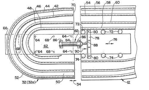
Referring to Figure 3 in conjunction with Figure
1, turnaround ~rack assembly 32 i~ shown in greater detail,
including the above-described track~ 42, 44 and 46, 48 on
each side of the conveyor. It should be understood that
the more detailed deplction of Figure 3 shows only one ~ide
of the turnaround track assembly, ~uch as looXing inside-
out at the left side of the con~eyor when facing inwardly
toward the lower landing. ~he opposite or right side i8
identical. Consequently, the numeral 32a is being used for
the suba~sembly shown in Figure 3. Tracks 42, 44, 46, 48
are mounted on a common or base support pla~e 50 which i8
shown to have a generally semi circular outer periphery 52~
The guide track means on main frame 12 (Fig. 3~ are simi-
larly constructed to include an inner support track 54 and
an outer hold-down track 56 for step support rollers 36,
and an inner support track 58 and an outer hold-doT~n track
60 for trailer rollers 38. Still re~erring to Flgur~ 3, as
stated above, turnaround track assembly 32 (there~ore,
subassembly 32a) is mounted for movement in the diraction
of double-headed arrow 34 relative to main frame 12 and
tracks 54-60.
~7~
M9102
- 7 -
The movable mounting of each subassembly 32a, on
each side of the conveyor, i~ provided by a slider plate 62
fixed by appropriate fastening means 64 to base support
plate 50 of turnaround track subassembly 32a. A second
plate 66 is fixed by appropriate fastening means 68 to base
support plate 50, on the outside of the base support plate,
to provide further rigidity for slider plate 62. The
slider plate extends beyond an inner edge 70 of ba~e
support plate 50 and is disposed between three top rollers
72 and three bottom rollers 74 journalled on stationary
main frame 12. Therefore, slider plate 62 is movable
between rollers 72 and 74 in the direation o~ double-headed
arrow 76 to move turnaround track subassembly 32a therewith
in the direction of double-headed arrow 34. ~ push block
in the form of an angle beam 78 is fixed to stationary main
frame 12 by bolts or other appropriate ~astening means 80.
The push block overlies and is spaced from the inside of
the slider plate 62. -~
As stated above, Figure 3 is a depiction looking
"inside-out" at one side of the e calator below landing 24.
There~ore, it should be understood that one of the turn- `
around track subassemblies 32a, slider plates 62, rollers
72 and 74, and push blocks 7~ are provided at each side of
the escalator or conveyor system.
The invention contemplates a hydraulic chain
tensioning system operatively associated between the turn-
around track subassemblies 32a and the stationary main
frame 12 on each ide of the escalator system to equalize
tension on the step chains on opposite ~ides of the con-
veyor. Still referring to Figure 3, a hydraulic ten~10ning
device in the form of a piston and cylinder device, gener-
ally designated 82, is interconnected be~ween each turn-
around track subassembly 32a and stationary main ~rame 1~
on each s1de of the escala~or. Each ten~ioning devica
includes a cylinder 84 mounted by bracket~ 86 to slider
plate 62. A piston 88 projects from the inner end o~
2~
M9102
~ 8 -
cylinder 84 and is engageable with push block 78 fixed to
stationary main frame 12. Therefore, upon application of
pressurized fluid to cylinder 84, piston ~8 will move in
the direction of arrow 90 against push block 78 which, in
turn, moves turnaround track subassem~ly 32a away from the
main ~rame.
Figura 4 shows an end view o~ the hydraulic
tensioning system to illustrate that a hydraulic piston and
cylinder ~evice 82 is locatad at each opposite side of ~he
escalator, along with the respective slider plates 62,
rollers 72 and 74, base support plates 50 and support
plates 66. In addition, rollers 72 and 74 can be seen to
bs journalled on bolt like ~tub shafts 92.
As stated above, the invention ~ontemplates that
hydraulic piston and cylinder devices 82 be hydraulically
connected to equalize tènsioning on tha step chains between
the turnaround track subassemblies at opposite sides o~ the
escalator or conveyor. More particularly, 3till re~erring
to Figure 4, each cylinder o~ each piston and cylinder
device communicates hydraulically through conduits 96 to a
common accumulator 98 which, in turn, communicates through
a conduit 100 to a source 102 of pressurized hydraulic
fluid. Therefore, the pressura in the cylinders are
maintained equal, whereby the ~orces of the pistons on push
blocks 78 likewise are equal. The piston and cylind~r
device~, themselve , should be mounted to be substantially
parallel to each other, i.e. in a common plane, to as~ure
precise applications of equal forces on push blocks 78.
Accumulator 98 provide~ both a re~arvoir and
pressure or tension regulation. Teneion on the Btep chains
is adjusted by controlling the accumulator charge prsssure.
The accumulator charge can be monitored by an appropriats
pressure gauge 106 for ea6y visual observation. 0~ cour~e,
accumulator charge monitoring could be accompli hed by
appropriate electronic controls of the escalator by mean~
of a pre sure transducer or a switch. With ~uch a hydrau-
M9102
g _
lic system, emergency shutdown could be triggered either by
a loss of pressure (i.e., chain tension), pressure fluctua-
tion, ~low detection or any combination thereof, such as
resulting from an obstructlon or impact to the turnaround
track subas~emblies or other abnormal operating conditions.
Cushioning or shock absorption also is possible with the
use of simple orifice~ or flow control valves operatively
associated with the hydraulic devices. All o~ these
advantages are afforded by the hydraulic tensioning system
of the inv~ntion, which otharwise would be impossible or
impractical with mechanical tensioning systems hereto~orQ
available.
It will be understood that the invention may be
embodied in other specific forms without departing from the
spirit or central characteristics thereof. The present
examples and embodiments, therefore, are to be considered
in all respects as illustrative and not restrictive, and
the invention is not to be limited to the details giv~n
herein.