Note: Descriptions are shown in the official language in which they were submitted.
~ /&~ J b ~ ' 3
:,~,;,,: ,.
1 "Windmill"
3 This invention relates to windmills.
With the depletion of the world's mineral resources
6 alternative sources of energy have become more popular
7 and one of these is wind power. It has been proposed
8 to erect large windmills having wind drive blades
9 connected with generators for producing electricity.
lo However, the large variations in wind speed have
11 necessitated the incorporation of pitch variation for
12 the blades so that a generally constant blade rotation
13 is approximated.
14 --
GB-A-?,169,663, in the name of the present applicant,
16 discloses a construction for a windmill blade wherein
17 the blade is connected to a hub by means of an
18 intermediate portion, the intermediate portion being
19 connected to the hub and to the blade ~y first and
second parallel hinges and being itself hinged along a
21 third axis extending diagonally between the parallel
22 hinges.-;The-hub, blade and intermediate portion aré
23 moulded~integrally from plastics material, the hinges
24 comprising resilient creases in the plastic. In a rest
condition, the creases`orient the blade at an angle to
.; .
.
-
,: , ' ' : :.
vv ~
(-aV~7 2
1 its plane of rotation and rotation of the blade creates
2 a centrifugal force on the blade which tends to flatten
3 out the hinge creases, thereby reducing the pitch angle
4 of the blade in response to changes in its speed of
rotation caused by variations in wind speed.
6 '
7 The blade of GB-A-2,169,663 thus reacts automatically
8 to changes in wind speed by reducing its pitch angle as
9 the wind speed increases and increasing its pitch angle
as the wind speed drops. However, it is not responsive
11 to variations in the torsional loading on the shaft
12 which it is driving, i ~ at any given wind speed the
13 pitch angle will not~ ange in response to changes in
14 torque at the,shaf,~
16 It is an object of the present invention to provide a
17 windmill having blades which alter their pitch angles
18 automatically in response to changes in both wind speed
19 and load.
21 According to the present invention there is provided a
22 windmill including a plurality of windmill blades
23 extending outwardly from and spaced equi-angularly
24 about a central axis of rotation and each having a
leading edge and a trailing edge, the blades being
26 connected together at a central hub portion and adapted
27 to rotate about said central axis in a plane of
2E rotation normal to said central axis, each of said
29 blades having an inner section hingeably attached to
said hub portion along a first hinge axis and an outer
31 section hingeably connected to said inner portion along
32 a second hinge axis, said second hinge axis extending
33 from a point on the trailing edge of the~blade adjacent
34 to the first hinge axis to a point on the leading edge
3~ of the blade remote from the first hinge axis, the
"
~', .
.
~' .
G~J9
- - ~
3 ~-3 . .J.~1;. .
1 inner section being resiliently biased towards a rest
2 position wherein it lies in a plane at an angle to the
3 plane of rotation and wherein the outer section is
4 disposed at a pitch angle relative to the plane of
rotation, such that force applied to the blade against
6 the bias force tends to reduce the angle between the
7 plane of the inner section and the plane of rotation
8 and the pitch angle of the outer section.
Preferably, said hub portion is attached to a rotatable
11 shaft extending rearwardly fro~ the hub along the axis
12 of rotation, and said inner section of each blade is
13 angled outwardly and rearwardly from the hub when in
14 its rest position.
16 Preferably also, said inner section of each blade is
17 biased towards its rest position by at least one
18 resilient bias element connected between the hub
19 portion and the inner section.
21 Preferably also, said hub portion includes an anchoring
22 member spaced from the first hinge axes along the axis
23 of rotation, said at least one resilient bias member of
24 each blade having a first end connected to the
anchoring member and a second end connected to the
26 inner section of the blade.
27
28 Preferably also, said second end of said at least one
29 resilient member`of each blade is attached to a plate
member secured to an inner surface of the inner section
31 facing the axis of rotation. -
32
33 Suitably, said at least one resilient bias member of
~`~ 34 each blade may be a coil spring.
' ~ - ' ' ' .', ' ' ' ,, ' '
~`' ' .
~: .
WO gl/!''4213 l'C~/G~1/00
~ ^JU~ ~ 4
1 The inner section of each blade may be generally
2 triangular, a first edge thereof extending along said
3 first hinge axis, a second edge thereof extending along
4 said second hinge axis and a third edge thereof forming
part of the leading edge of the blade.
7 The angle between the first and second hinge axes of
8 the inner section of each blade may be approximately
g 45 .
11 Preferably, said in~e,r and outer sections of each blade
12 are formed integ~a`ll-y from plastics material creased
13 along said seco~ hinge axis.
14
Preferably also, each blade is attached to the hub by
16 means of a flap formed integrally with said inner
17 section and creased along said first hinge axis.
18
19 An embodiment of the present invention will now be
described by way of example, with reference to the
21 accompanying drawings in which:- -
22
23 Fig. 1 shows a schematic front and side view of a -
24 windmill in accordance with the present invention;
Fig. 2 illustrates a single blade of a windmill in
26 accordance with the present invention:
27 Fig. 3 shows sections A-A and B-B, through the
28 blade of Fig. 2: , -,,
29 Pig. 4 is a schematic, rear perspective view of
30 ,~ the hub and inner blade portions~,of a windmill in
. . .
31 accordance with the invention; and ,
32 ~ Fig. 5 is a schematic, fragmentary side view of
33 , the,blades, hub and housing of,the wind~ill of
34 Fig. 4. - ' ~ ' -
~ '
.
~3~ 2`._~ ~/&i~t~l /fl~i~fl~
,
~207~047
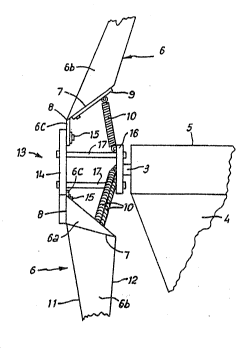
1 Fig. 1 shows a windmill 1 for generating electricity,
2 having a support post 2 secured to the ground through a
3 base plate, not shown, the post 2 having mounted on it
4 a rotatable director 4 with a tubular housing 5. An
electrical generator is mounted within the housing 5
6 and connected to wiring which runs through the
7 director 4 and post 2 and thence to a location where
8 electricity is required. The rotor of the generator is
9 driven by a rotatable shaft 3 which carries at its end
a hub portion 13 from which extend.three blades 6. In
11 use the director 4 ensures that the blades 6 are always
12 disposed in a direction for rotation by the wind.
13
14 Each windmill blade 6 comprises a generally triangular
inner section 6a hingeably connected to the hub 13
16 along a first hinge axis 8 and an outer section 6b
17 hingeably connected to the inner section 6a along a
18 second hinge axis 7. The inner and outer blade
19 sections 6a and 6b are formed integrally from plastics
material creased along the second hinge axis 7. The
21 inner section 6a is secured to a main hub member 14 by
22 means of an integrally formed flap 6C, creased along
23 the first hinge axis 8, which is attached to the hub
24 member 14 by means of bolts, rivets or the like 15.
26 The creases along the hinge axes 7 and 8 are resilient,
27 biasing the inner section 6a towards a position where
28 it lies in a plane at an angle to the plane of rotation
29 of the bIades, extending outwardly and rearwardly from
the first hinge axis 8, and biasing the outer section
31 6b towards a position where it extends outwardly from
32 the axis of rotation of an angle to the plane of the
33 inner section 6a and at a pitch anqle.to the plane of
. . 34 rotation. The second hinge axis 7 extends from a point
on the trailing edge ll of the blade 6 at the base
.
' '
.
':
'
, .
., .
. . .
:
`YV~1/ 2~,9 ~ J~J:/~v~Z~
2 0 7~0 47 6 ,,
1 thereof adjacent the first hinge axis 8 to a point on
2 the leading edge 12 remote from the first hinge axis 8.
4 In the illustrated embodiment the angle between the two '
hinge axes in the plane of the inner section 6a is
6 approximately 45.
7 ~;-
8 The resilience of t~'creases along the first hinge
9 axes 8 is augmented''~by resilient bias members, such as
coil springs 10 ~connected between the hub 13 and the
11 inner sections 6a. The coil springs 10 each have a
12 first end connected to an anchoring member in the form
13 of a triangular plate 16, spaced rearwardly from the , :,
14 main hub member 13 along the axis of rotation by rods
17 at each'vertex thereof, and a second end connected
16 to a plate 9 attached to the inner surface of each
17 inner section 6a facing the axis of rotation. The
18 anchoring plate 16 also secures the hub 13 to the shaft
I'9 3.
'
21 Each of the blades iS manufactured from a sheet of
22 plastics material such as PVC or high density
. . ~
23 polyethylene, which is folded into an aerodynamic
24 hollow tear drop shape. The inner section 6a of the ,,
~blade 6 is formed by gluing the two sides of the
26 material together and the creases along the hinge
27 aX-s 7 and 8 are produced by heat welding.
28'
29 ~ The resilience of the creases along the hinge axes 7
and 8 and of the springs 10 biases the blades towards
31 the rest position'as described above. As the blades
32 rotate~, centrifugal force'acting along the longltudinal
33 axes of the blades against the biasing forces tends to
34 -reduce~the angles between the plane of the inner
35~ section 6a and the plane of rotation and between the
~ .. :: ::: :
, ,. : . .
~.' ~ ' -, .
w~ 09~
.
.. . . . . ..
~7~v~7 : :.
1 planes of the inner and outer sections 6a and 6b, so
2 reducing the pitch of the blades. The pitch angle
3 progressively reduces as the wind speed increases, and
4 increases as the wind speed drops. The blades thus
respond automatically to variations in wind speed so as
6 to maintain a substantially constant speed of rotation
7 of the blades. The outer blade sections themselves
8 twist through approximately 15 to give progressive
9 stall with increasing wind speed to prevent drop-off of
power after optimum wind speed. The design of the
li blades thus provides constant power with increasing
12 wind speed beyond optimum.
13
14 The configurat-ion of the blade, with the second hinge
axis extending from the base of the blade on the
16 trailing edge to a point spaced outwards from the base
17 on the leading edge, means that the pitch angle also
18 responds to variations in the torsional load on the
19 shaft, so that the pitch angle increases in response to
increased load and reduces in response to decreased
21 load; i.e. the limiting speed of rotation which is
22 maintained by the variation of the blade geometry in
23 response to varying wind speeds increases as the load
24 increases (the limiting speed for no load is less than
25~ the limiting speed when a load is applied).
26~
27 Modifications and improvements may be incorporated
28 without departing from the scope of the invention.
29
3~ - -
31
32
33
34 ~ ~ -
:.~ . : , .
.~: ., . . ~:
,. .
; .. .