Note: Descriptions are shown in the official language in which they were submitted.
~ UJ~
--1--
H~N~LE FOR MANIPULAl~G A L~P~OSCOPIC TOOI,
s
BP~CKGROUND OF THE INYENTION
1. Field of the InYention
The present invention relates to the field of laparoscopic or endoscopic
surgery, and more particularly to a handle mechanism for manipulating a distal
laparoscopic surgical tool inserted through a small incision in the body and positioned
within the body adjacent an organ which is to be excised or repaired, allowing
surgical procedures to be performed thereon.
2. Discussicn Of The Prior ~1~
A surgeon, when performing an operation on a patient, is often
obstructed in his efforts to excise diseased or damaged tissues or organs by
surrounding tissues~ fatty deposits, arteries, or other organs. It has generally been the
case, when performing gastro intestinal surgery, i.e. surgery within the abdominal
cavity, to make a large cut in the abdomen wall to produce a suitable opening to: ~ ~ allow access to the interior organs. This cut was generally large enough to allow the
use of human hands, either those of the surgeons or those of a member of the surgical
team, as a retractor. Surgical personnel would thus insert their hands through the
incision into the abdominal cavity to push and hold organs and other obstructing
components away from the surgical objective.
::
;
~ ~35
:
,. . .
.
2~.?~,.J~
~ ecently, at least in part as a result of the evolution in electronic video
technology, a surgical procedure known as laparoscopic surgery has undergone a
marlced increase in popularity. The laparoscope consists of a long thin rigid tube, and
5 residing at one end of the tube is a viewing lens, while at the opposite end is a
camera hook up and an eye piece. A small incision in the area of the surgical
objective is made and the laparoscope is partially inserted into this incision, viewing
lens first. High definition video cameras and monitors are then attached to the
10 camera hook up connector on the part of the laparoscope which remains positioned
exteriorly of the body. In this manner, a surgical team can get a clear picture of the
affected internal area without resorting to radical, disfiguring surgical incisions to
physically open the patient. Other small incisions may then be made through the
surface of the skin in the vicinity of the surgical objective. Through these incisions,
15 miniaturized surgical instruments such as scissors, forceps, clamps and scalpels may
be inserted to perform various surgical procedures. The entire interiorly performed
surgical procedure is monitored from the exterior through the high definition
television monitor. In this manner radical incisions and scarring are avoided while
20 undertakin:g surgical repair or removal of damaged or diseased organs. Another
benefit of laparoscopic surgery is the significantly reduced recovery time, whencompared to standard surgical procedures, due to the minuscule size of the scalpel
incisions and avoiclance of the massive internal traumatization known in standard
25 surgical procedures. Accompanying the reduced recovery time are, of course, greatly
reduced costs.
Therefore, there is a need to provide a clevice which may be partially
inserted through a tiny surgical incision in the abdominal wall, which n-lay be used
during laparoscopic surgery within the abdominal cavity, and which is useful to
y~
manipulate an endoscopic surgical tool held dista~ly at the end of the device within the
abdominal cavity adjacent that organ which is being excised or repaired.
Several implements are known which are useful to perform certain
5 surgical procedures. For example, U.S. Patent No. 2,898,915 discloses an implement
for particularly tying off open blood vessels astringently. When the operating handle
is suitably depressed, a catch is released so that the main slide member under the
action of a spring will slide cluickly forward into the easing, allowing the tying head
10 of the implement to move over the forceps, with its front surface even extending
slightly beyond. For a further device for ligaturing blood vessels see U.S. Patent No.
2,898,916 wherein by pressing the operating lever against the casing of the device, a
second lever connected to the operating lever is moved laterally, and presses with a
closing effect against a pivotally connected clamping arm so that it closes against a
5 stationary clamping arm, elamping the blood vessel elosed so that it may be ligatured.
However, these types of implements are not use-ful for imparting
longitudinal and rotative movements to various endoseopie tools to manipulate their
action during endoscopic surgery.
;.
SUMl\~A~ OF T~I~ INVENTION
.
The present invention provides a novel handle for an endoscopic or
25 laparoscopie tool whieh may be inserted through a tiny surgieal ineision in the
abdominal wall, which may be used during laparoscopie surgery within the abdominal
cavity, and which is useful to manipulate the endoscopie surgieal tool held distally at
the end of the device within the abdominal eavity adjaeent that organ which is being
excised or repaired. Accordingly, the clevice according to the present invention may
~q~ q~
- 4 -
impart longitudinal and rotative movements to various endoscopic tools
to manipulate their action during endoscopic surgery.
One embodiment of the present invention relates to a handle for
laparoscopic instruments, comprising:
actuating shaft means;
elongated casing means cooperating wi~h the actuating shaft means, the
actuating shaft means extending outward from the casing means and being
longitudinally movable for manipulating a laparoscopic tool attachable at the end of
0 the actuating shaft means opposite the casing means;
gripping means pivotally attached and extending generally axially along
the casing means, the gripping means and the casing means providing a pair of
operating handles movable toward and away from each other, the actuating shaft
means being longitudinally rnovable in a first direction by a pivotal motion of the
5 gripping means; and
detent means carried by the casing means for allowing the movement of
the shaft means longitudinally in the first direction while restraining longitudinal
movement of the shaft means in a second direction.
Another embodiment of the present invention relates to a handle
0 comprising:
a pair of concentric shafts~ the concentric shafts including an inner
longitudinally movable actuating shaft and an outer shaft;
an elongated casing cooperating with the concentric shafts, the
concentric shafts extending outwardly from the casing, the actuating shaft being
25 longitudinally movable to manipulate a laparoscopic surgical tool attachable at the
. . ,
2r~f~
- 4A~
distal end of the concentric shafts opposite the casing, the outer shaft being rotatable
about its longitudinal axis to further manipulate the laparoscopic tool;
an elongated grip member pivotally attached and extending generally
S axially along the casing, the griR member and the casing providing a pair of operating
handles movable toward and away from each other;
a rack longitudinal movable in the casing, the rack being longitudinally
movable in a first direction by a pivotal movement of the grip member toward the
casing, the actuating shaft being attached to the rack for longitudinal movement0 therewith; and
a detent carried by the casing, the detent allowing the longitudinal
movement of the actuating shaft in the first direction while engaging with the rack to
releasably restrain longitudinal movement of the actuating shaft in a second direction.
Yet anolher embodiment of the present invention relates to a handle
5 comprising:
a pair of concentric shafts, the concentric shafts including an inner
longitudinally movable actuating shaft and an outer shaft;
an elongated casing aligned axially with the concentric shafts, the
concentric shafts extending outwardly from the casing, the actuating shaft being
20 longitudinally movable to manipulate a laparoscopic surgical tool attachable at the
distal end of the concentric shafts opposite the casing, the outer shaft being rotatable
about its longitudinal axis to further manipulate the laparoscopic tool;
an elongated grip member pivotally attached and extending generally
axially along the casing, the grip member and the casing providing a pair of operating
25 handles movable toward and away from each other;
.. . .
~f~ 5~.
- 4B -
a rack longitudinally movable in the casing;
a link member pivotally interconnecting the grip member and the rack,
the rack being longitudinally movable in a first direction by a pivotal moYement of the
S grip rmember toward the casing, the link member translating the pivotal motion of the
grip member to longitudinal motion, the actuating shaft being attached to the rack for
longitudinal movement therewith;
a detent carried by the casing, the detent allowing the longitudinal
movement of the actuating shaft in the first direction while engaging with the rack to
0 restrain longitudinal movement of the actuating shaft in a second direction; and
a release member carried by the casing and longitudinally movable
therein, the release member being movable from a first position to a second position
to disengage the detent from the rack to allow the actuating shaft to move
longitudinally in the second direction.
A still further embodiment of the present invention relates to a handle
for laparoscopic instruments, comprising:
elongated casing means having means for rnolmting an elongated shaft
means thereon, the mo~mting means being aligned axially with the casing means; and
gripping means pivotally attached and extending generally axially along
20 the casing means, the gripping means and the casing means providing a pair of
operating handles movable toward and away from each other, the casing means
including ratchet means for incrementally adjusting an opening and closing stroke of
the gripping means relative to the casing.
Yet another embodiment of the present invention relates to a handle
5 for laparoscopic instruments, comprising:
- 4C-
elongated casing means;
actuating shaft means positioned at least partially within the casing
means in general axial alignment therewith, and extending outwardly of at least one
5 end portion thereof, the shaft means being longitudinally movable and adapted to be
associated with laparoscopic tool means for manipulation thereof;
gripping means attached to the casing means in a manner s-uch that the
gripping means and the casing means are movable relative to each other and adapted
to move the actuating shaft means longitudinally in a first direction when at least one
0 of the casing means and gripping means is moved toward the other; and
means adapted to allow longitudinal movement of the shaft means in a
first direction and preventing longitudinal movement in the opposite direction.
A still further embodiment of the present invention relates to a surgical
instrurnent comprising:
a handle assembly including an axially directed stationary handle and a
movable handle, the movable handle being pivotally connected to the stationary
handle and being moveable from a ~irst position at an angle to the stationary handle
to a second position in substantial parallel alignment with the stationary handle;
a body assembly comprising a pair of coaxial members attached at one
20 end to the handle assembly, including an inner rod member slidable within an
elongated outer tube member in response to movement of the handle assembly, the
body assembly terminating at an end remote from the handle assembly in a
reciprocatingly movable tool mechanism~ and
- 4D -
means positioned within the stationary handle of the handle assembly
for engaging the body assembly to provide incremental movement of the tool
mechamsm.
The device according to the present invention is a novel handle for a
laparoscopic or endoscopic instrument which may, by imparting longitudinal and
rotative motion selectively to a pair of concentric longitudinal shafts that extend
outwardly frorn the handle, manipulate a distal laparoscopic surgical tool held at the
opposite end of the shafts. In order to impart longitudinal motion to rnanipulate the
distal laparoscopic surgical tool, the handle is provided with an axially aligned,
elongated casing and a pivotally connected elongated grip member extending generally
axially along the casing. The grip member, together with the casing, provide a pair of
operating handles movable toward and away from each other. When the grip
mernber is squeezed laterally inward, longitudinal movement is imparted to the inner,
actuating shaft of the paired sha~ts. To impart longitudinal motion in a first direction,
the grip member pivots from a first position laterally inward to a second position
contacting along the casing and generally co-axial with the shafts.
The casing, into which the concentric shafts axially extend, encloses the
details of the present invention. A link member pivotally interconnects the gripmember and a raclc attached at the enclosed end of the actuating shaft and located
within the casing. The actuating shaft is connected to the racl~ so that it moves
longitudinally with the rack. As the grip member is squeezed inward towards its
second position, the link translates the pivotal motion of the grip member to
longitudinal motion to impart a longitudinal movement to the rack and actuating shaft
in the first direction toward the rear end of the casing. The longitudinal movement of
2~s~
- 4E -
the actuating shaft in the first direction, imparted by squeezing the grip member
laterally inward toward its second position, causes a manipulative longitudinal
movement to be applied to the distal laparoscopic surgical tool to perform a specified
'
~ :`
2~ i ~d~h'~i,~L.
surgical procedure. As may be appreciated, a longitudinal slot is provided in the
casing through which the link member extends to allow the link to move
longitudinally in the casing as the grip member is squeezed.
A detent enclosed within the casing allows the rack to slide therealong in
the first direction so that the rack and attached actuating shaft may move
longihldinally in the first direction. The detent engages with the rack to restrain
longitudinal movement of the rack and attached actuating shaft in a second direction,
opposite the Flrst direction, toward the front end of the casing. The detent and the
rack cooperate to allow for incremental "ratcheting action" which allows the
laparoscopic surgical tool to be selectively incrementally manipulated by squeezing the
grip member inward in suitable increments towards its second position. Thus~ thetool may be advanced throu~h a series of incremental positions as the grip member is
moved incrementally to its second position.
A release mechanism allows the rack and attached actuating shaft to
move longitudinally in the second direction. As may be further appreciated, the
release mechanism also allows the grip member and link member to return to theirfirst position. The release mechanism includes an elongated release member whichextends longitudinally into the casing. The release member is longitudinally movable
from a first locking position by finger action to a second pOSitiOI1 to release the detent
from its engagement with the rack. Included with the release mechanism, is a catch
located on the detent which when engaged by the release member, allows the release
member to disengage the detent from the rack. The catch is engaged by the enclosed
end of the release member when the release member is moved to its second position,
and, when the release member is moved to its second position allows the release
member to disengage the detent *om the rack. In order to impart longitudinal motion
to the actuating shaft and rack in the second direction when the release member is
-6- 2~.~ J'~
moved to its second position, a spring located between the casing and the rack acts on
the rear end of the rack to longitudinally move the actuating shaft and rack in the
second direction. The longitudinal movement of the actuating shaft in the second5 direction, imparted by moving the release button to its second position, causes a
further manipulative longitudinal movement to be applied to the clistal laparoscopic
surgical tool to return the tool to its initial conf1guration.
~ thumb wheel is engaged with the outer shaft, and, when rotated,
1 O causes the shafts to rotate about their longitudinal axis. The rotational movement of
the actuating shaft, imparted by rotating or turning the thumb wheel, causes a
manipulative rotational movement to be applied to the distal laparoscopic surgical tool
to perform a further specified surgical procedure. Accordingly, the manipulativerotational movement may be applied to rotate the laparoscopic tool in an arc about the
longitudinal axis of the concentric shafts Consequently, the tool may not need to be
repositioned in the body to access that bodily organ to be excised or repaired even
though the tool may be initially deflected from its designated plane of operation.
Instead, rotation of the thumb wheel may allow the tool to be repositioned within the
20 desired oerating plane. The rotational motion may be applied either clockwise or
counter-clockwise to align the surgical tool within the operating plane and to return
the tool to its initial position.
Thus, after a trocar is partially inserted in the body, the laparoscopic
25 surgical tool attached at the distal end of the concentric shafts may be inserted
through the cannula of tlle trocar and positioned adjacent the organ to be excised or
repaired. With the aid of a laparoscope, the surgeon can manipulate the distal
laparoscopic surgical tool by squee~ing the grip member laterally, in suitable
increments, inward toward the casing and alignment with the axis of the concentric
shafts to selectively apply longitudinal motion to the laparoscopic surgical tool. Thus,
--7--
the tool may be selectively manipulated to perform a specific surgical procedure.
When the grip member is moved incrementally toward the casing, the detent and the
rack cooperate to allow for the incremental "ratcheting action" which a]lows the5 ]aparoscopic surgical tool to be selectively incrementally manipulated.
Manipulation of the laparoscopic tool to position the surgical tool in the
plane of operation may be performed by rotating the thumb wheel. As may be
appreciated~ this may allow better use of the laparoscopic surgical tool. Pressing
10 inward on the push button end of the release member to disengage the detent from the
rack, causes the laparoscopic surgical tool to return towards an initial configuration
under spring influence.
13RIEF ~ESCRIPTION OF Tl-IE DRAWINGS
The foregoing features of the present invention will become more readily
apparent and may be understood by referring to the following detailed description of a
preferred embodiment of the handle according to the present invention, taken in
20 conjunction with the accompanying drawings, in which:
Fig. 1 illustrates a perspective view of a preferred embodiment of the
handle for laparoscopic instrumentation according to the present invention;
Fig. 2 illustrates a cut-away perspective view of the handle of Fig. l;
25 and
Fig. 3 illustrates a top view of the handle of Fig. l.
. .
~ -
DETAILED DESCl~lPrION OF THE P~EFERREO El`/I~D~NT
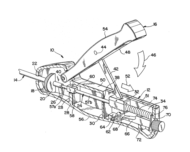
~efelTing to Fig. 1, a preferred embodiment of the handle, shown
5 generally as 10, is shown. An elongated casing 12 encloses the essential parts of the
invention, which are described in detail hereafter. Handle 10 is suilable for
manipulating a distal laparoscopic or endoscopic surgical tool, not shown in thefigures, which is attached to the opposite, distal end of a pair of concentric
10 longitudinal shafts 14. Longitudinal shafts 14 extend outward]y from casing 12, and
allow the distal laparoscopic surgical tool to be inserted tllrough a small incision in
the body and positioned within the body adjacent the organ which is to be excised or
repaired, thus allowing surgical procedures to be performed thereon without the need
of severe incisions in adjacent body tissues. ~s discussed in detail hereafter,
15 concentric shafts 14 may comprise a longitudinally movable inner actuating shaft and
an outer shaft, which allow the surgeon to control different types of endoscopic tools
requiring reciprocal or rotational manipulations. Although it is preferred that
concentric shafts 14 may comprise a longitudinally movable inncr shaft and an outer
20 shaft, it is within the scope of the invention that the outer shaft be longitudinally
movable over the imler shaft.
An elongated grip member 16 is pivotally connected to casing 12.
Elongated casing 12 is aligned axially with concentric shafts 14 for purposes as25 discussed hereafter. By squeezing grip member 16 inward as described in detail
hereafter, longitudinal motion may be transferred to the inner shaft. A thumb wheel
18 may be rotated selectively by the surgeon to impart rotary motion to the outer
shaft, so that shafts 14 may be rotated about their longitudinal axis. As shown in Fig.
1, thumb wheel 18, may be carried within a pair of opposed slots 20 on opposite
sides of casing 12.
- 9 -
Referring to Fig. 2 for details enclosed by casing 12, concentric shafts
14 extend longitudinally into casing 12 through an opening 22 in the front end of
casing 12. Concentric shafts 14 include an inner longitudinal actuating shaft 24 and
5 an outer longitudinal tubular shaft 26, concentrically positioned around inner shaft 24.
Actuating shaft 24 extends longitudinally into casing 12 through a pair of opposed
openings in inner walls 2~, 30. Included with actuating shaft is a rack 32 located in
the rearward chamber 34 of casing 12 behind wall 30. ~ctuating shaft 24 connects at
1 0 its inner end to rack 32 by any suitable means so that actuating shaft 24 may be
moved longitudinally by rack 32, as well as rotatably, if desired. Rack 32 is
positioned so that its teeth 36 extend longitudinally along the axis of actuating shaft
24. Opening 38 in wall 30 through which actuating shaft 24 longitudinally extends
may provide a bearing surface on which actuating shaft 24 may slide longitudinally,
1 5 while restraining lateral motion of actuating shaft 24 and rack 32. Attachable at the
opposite, distal ends of shafts 24, 26 is a laparoscopic surgical tool, not shown in the
figures, which may be manipulated by selective longitudinal and rotative motions of
shafts 24, 26 to perform selected surgical procedures.
20 . As shown in Fig. 2, elongated grip member 16 is pivotally connected atone end to casing 12 by suitable means such as a pivot pin 40. Elongated casing 12
is aligned axially with concentric shafts 14, and grip member 16 extends generally
axially along casing 12, as shown in Fig. 3, from its pivotal connection with casing
25 12 toward the rear of casing 12. Referring again to Fig. 2, grip member 16 and
casing 12 together provide a pair of operating handles movable toward and away from
each other. Consequently, a handle is provided which is aligned axially with the axis
of the concentric shafts 14. Thus, the user may apply squeezing motion about thecommon axis of shafts 14. It is known to pIovide squeezable operating handles that
are configured perpendicular to the axis of the concentric shafts. However, at times
: ;
--10--
this handle configuration is diff1cult for the user to manipulate, which may lead to
unpreferred delays in performing the necessary surg;cal procedure. However, as
provided by the present inventioll, the ability to move grip member 16 and casing 12
5 toward and away from each other about the common axis of shafts 14 alleviates this
problem and allows the user to more easily manipulate the surgical tool under more
varied operating conditions. Thus, surgical procedures may be more timely and
safely performed.
0 A link member 42 extends between grip member 16 and rack 32 and is
pivotably connected to both at a pivot point. One end of link rnember 42 is pivotally
connected on grip member 16 a suitable distance from its pivotal connection withcasing 12 by suitable means such as a pivot pin 44, and the opposite end of linkmember 42 is similarly attached to rack 32. Grip member 16 is pivotally movable
1 5 laterally relative to casing 12 from a f1rst position as shown in Fig. 2 inward in the
direction of arrow 46 to a second position, not shown in the figures, co-axial with
shafts 14, in which a planar surface 48 extending longitudinally along the lowersurface of grip member 16 contacts longitudinally along a similar planar surface 50
extending along casing 12. A longitudinal slot 51 in casing 12 allows link member 42
and rack 32 to move longitudinally in casing 12, and may include a cooperating
flange and bevel system to provide a track in casing 12 in which rack 32 travels.
As grip member 16 is moved laterally inward toward its second position
about its pivotal connection with casing 12, ]ink member 44 translates the pivotal
motion of grip member 16 to longitudinal motion to move rack 32 longitudinally in a
first direction as indicated by arrow 52 toward the end of casing 12. Movement of
rack 32 longitudinally by the inward movement of grip member 16 toward its second
position causes actuating shaft 24, connected thereto for movement therewith, to move
longitudinally in the same direction as indicated by arrow 52. ~ovement of actuating
shaft 24 longitudinally allows the laparoscopic surgical tool attached at the distal ends
`' ''' '
of shafts 24, 26 to be manipulated by the longitudinai motion of actuating shaft 24 to
provide a specified surgical procedure.
Extending along the upper surface of grip member 16 is an arcuate
5 convex section 54. Located opposite arcuate convex section and extending along the
bottom surface of casing 12 is a similar symmetrical arcuate convex section 56.
Opposed arcuate convex sections 54, 56 are provided so that handle 10 may be more
easily held and manipulated by the user to move the operating handles toward andO away from each other~ and it is apparent that these curved surfaces may be varied in
length and height to provide for an anatomically comfortable grip.
Referring to Fig. 2, actuating shaft 24 may include a pair of axially
aligned longitudinal shaft portions 57a, 57b. ~ connector in ~he form of a block 58,
located between shaft portions 57a, 57b, may rotatively interconnect shaft portions
1 5 57a, 57b. Block 58 may rotatively connect with shaft portions 57a, 57b by any
suitable means so that shaft portion 57a may rotate about its longitudinal axis. Block
58 is adapted to slide longitudinally within a notch 60 in wall 28. Preferably, notch
60 has a complementary shape to block 58. As shown in Fig. 2, block 58 may have
20 a square cross section, although other suitable cross sections such as triangular are
also within the scope of the invention. ~s shown in Fig. 2, notch 60 has a
complimentary square shape, but may have other suitable complementary cross
sections to complement other cross sections of block 58 such as a triangular cross
25 section. Block 58 is further provided with a suitable longitudinal dimension such that
block 58 remains positioned in notch 60 during the longitudinal movements of shaft
24. Alternatively, block 58 may be eliminated and shaft 24 may be rotatively
connected directly to rack 32, such that a notch or circumferential groove is provided
to allow for rotation of the shaft 24 while maintaining axial movement. Block 58
may further be adapted to releasably connect with shaft portion 57a so that shafts 14
may be disconnected from casing 12.
- 1 2 - ~,~w
A detent provided in the form of a leaf spring 62 allows for the
longitudinal movement of activating shaft 24 and rack 32 in the first direction while
restraining the longitudinal movement of activating shaft 24 and rack 32 in a second,
5 opposite direction toward the front end of casing 12. Leaf spring 62 may be fixedly
attached at its lower end within a lateral slot 64 in casing 12. Leaf spring 62 extends
angularly from slot 64 upwards and toward the rear of casing 12, with its upper end
bearing against rack 32. The angular e~tension of leaf spring 62 rearwardly allows
teeth 36 of rack 32 to slide rearwardly in the rlrst direction across the upper,contacting end of leaf spring 62.
To restrain longitudinal movement of activating shaft 24 and rack 32 in
the second or opposite direction, the upper end of leaf spring 62 biases against rack
32 and engages with the teeth 36 of rack 32 to prevent longitudinal movement of shaft
1 5 24 and rack 32 toward the front of casing 12. Leaf spring 62 and rack 32 cooperate
to allow for incremental "ratcheting action" which allows the laparoscopic surgical
tool to be selectively incrementally manipulated by squeezing grip member 16 inward
in suitable increments towards its second position. Accordingly, the surgical tool may
20 go through a series of incremental positions as the tool is manipulated by the
longitudinal motion of activating shaft 24. It is also contemplated that the pitch and
spacing of the teeth 36 may be varied along the length of rack 32 to provide for fisle
or s~oarse adjustment during opening and closing. The rearward end of the rack 32
25 may have teeth having greater spacing between them to allow for coarse adjustment,
while the teeth at the forward end may be closely spaced to provide for fine
adjustment.
To return the laparoscopic surgical tool to its initial position, handle lO
is provided with a release means for releasing leaf spring 62 from its engagement
with rack 32 to allow longitudinal movement of the actuating shaft 24 in the second
direction. In a preferred embodiment, the release means is provided by an elongated
- 1 3 - 2 ~
release member or push button 66 and a catch 68 on leaf spring 62, which when
engaged by the end of elongated member 66 when it is moved longitudinally to itssecond position as described hereafter, causes the upper end of leaf spring 62 to be
5 forced downwardly, thus disengaging leaf spring 62 from teeth 36 of rack 32 and
allowing rack 32 and actuating shaft 24 to move longitudinally in the second direction
toward the front of casing 12. As may further be appreciated, the release means also
allows grip member 16 and link member 42 to return to their first position when
1 0 release member 66 is moved to its second position.
~ elease member 66 extends longitudinally through an opening 70 in ~he
rear end of casing 12, where its exposed push button end may be manipulated by
pushing to move release member 66 longit~Jdinally. :E~elease member 66 is positioned
longitudinally within casing 12 so that its enclosed end may engage catch 68 when
1 5 release member 66 is moved to its second position. ~ ledge 72 extends sideways
across rearward chamber 34 of casing 12 and prevents release member 66 from
moving laterally.
To normally restrain rack 32 and actuating shaft 24 from moving
20 longitudirially in the second direction, biasing means in the form of a compression
spring 74 is included with the illustrative release means. Spring 74 retains release
member 66 in a first locking position, with its enclosed end disengaged from catch
68. Surrounding release member 66 near its exterior end is a shoulder 76. Spring 74
25 is located between rack 32 and shoulder 76, and acts against shoulder 76 to normally
retain release member 66 locked in its first position, with its enclosed end disengaged
from catch 68 as shown in Fig. 2. Spring 74 may be a constant force spring, or may
also be a variable force spring in order to allow for easy movement at the beginning
of the handle stroke and a harder movement at he end of the stroke to protect the tool
mechanism at the end of the shafts.
When release member 66 is moved longitudinally inward toward the
front of casing 12 to the second position by finger action pushing on the external
portion of release member 66, the enclosed end of release member 66 engages withcatch 68 to force the upper end of leaf spring 62 downwardly, thus disengaging leaf
spring 62 from the teeth 36 of rack 32 and allowing rack 32 and actuating shaft 24 to
move longitudirlally in the second direction toward the front of casing 12.
Longitudinal movement of actuating shaft 24 and rack 32 in the second
1 0 direction toward the front of casing 12 may also be provided by the influence of
spring 74. Referring to Fig. 2 for details, spring 74 is compressed longitudinally
between rack 32 and shoulder 76. When leaf spring 62 is disenga~ed from teeth 36of rack 32 by the movement of release member 66 to its second position, spring 74
biases against the rearward face of rack 32, causin~ rack 32 and actuating shaft 24 to
move longitudinally in the second direction toward the front of casing 12. Movement
of actuating shaft 24 longitudinally in the second direction allows the laparoscopic
surgical tool attached at the distal ends of shafts 24, 26 to be retumed by the
longitudinal motion of actuating shaft 24 to their initial configuration.
In a preferred embodiment, concentric shafts 14 may be interconnected
so that shafts 14 rotate together about their longitudinal axis. To allow concentric
shafts 14 to rotate together, thumb wheel 18 may engage shaft 26 so that rotation of
thumb wheel 18 causes shafts 14 to rotate. In a preferred embodiment, thumb wheel
18 may extend radially from shaft 26, and is suitably affixed thereto so that rotation
of thumb wheel 18 causes shafts 14 to rotate to allow the laparoscopic surgical tool
attached at tlle distal ends of shafts 24, 26 to be further manipulated in both clockwise
and counter-clockwise directions to provide a further specified surgical procedure.
One preferred further manipulation is to apply the rotational movement to rotate the
laparoscopic tool in an arc about the longitudinal axis of concentric shafts 14.Consequently, the tool may not need to be withdraw and repositioned in the body to
-15 - 2 .
access that bodily organ to be excised or repaired, even though ~he tool may be
initially defiected from its clesignated plane of operation. Instead, rotation of thumb
wheel 18 may allow the tool to be repositioned within the desired operating plane.
In operation, a trocar is partially inserted into the body, and the distal
laparoscopic surgical tool attached at the end of shafts 1~ of handle lO may be
inserted through the cannula of the trocar and positioned laparoscopically adjacent the
orgaul to be excised or repaired. With the aid of a laparoscope, not shown in the
10 ~;gures, the surgeon can manipulate the distal laparoscopic surgical tool by squeezing
grip member 16 laterally inward toward casing 12 about the axis of longitudinal shafts
14 to apply longitudinal motion to the laparoscopic surgical tool to manipulate the tool
to perform a specif1c surgical procedure. Manipulation of the laparoscopic surgical
tool to best position the laparoscopic surgical tool in the plane of operation may be
15 performed by rotating thumb wheel 18 in clockwise or counter-clockwise directions.
Pressing inward on push button 66 to disengage leaf spring 62 from rack 32, causes
the laparoscopic surgical tool to return towards an initial configuration under the
influence of spring 74.
20 In addition, it is contemplated that release member 66 may be manipulated to disable
leaf spring 62 to allow for free opening and closing of grip member 16 in relationship
to casing 12.
While the invention has been particularly shown and described with
25 reference to a preferred embodiment, it will be understood by those skilled in the art
that various modifications and changes in form and detail may be made therein
without departing from the scope and spirit of the invention. ~ccordingly,
modifications such as those suggested above, but not limited thereto, are to be
considered within the scope of the invention.