Note: Descriptions are shown in the official language in which they were submitted.
2~7.~0
,
T~ OL D~ IN ?~ P~ r~ aED~
o~ the I~ve~tio~
The invention pertai~s to smoke and fire
detec~ion ~ystems which utilize a plurality o~ spaced
apart sPn~ors or detector elements~ More particularly,
the invention pertains to such systems which include a
central control panel wherea~ a determination i5 made,
for each sensor, as to whether or not an alarm
condition exists.
Baokgroun~ of th~ I~Yo~t~ on
Smoke or fire detection systems which utilize
a plurality of detectors or sensors spaced-apart in a
region or area are known. One such system is disclosed
in Tice et al. U.S. Patent No. 4,916,432 entitled "
Smoke And Fire Detection System Communication" which is
assigned to the assignee of the present invention and
which is incorporated herein by reference.
Known systems often provide a fixed alarm
threshold at a control unit which is displaced ~rom the
sensors or detec~ors. The control unit communicates
with the detectors or sensors via a bidirectional
communication line of the type disclosed, for example,
in the Tice et al. patent. Circuitry at the control
unit senses a value or values returned ~rom a selected
detector or sensor which are indicative of a current
ambient condition.
The sensed value or values is/are compared to
a pre~tored threshold value which may be the same ~or
all units. I~ the value or values returned ~rom the
selected detector or sensor exceed the prestor~d
threshold value, the control unit makes a determination
as to whether or not the system should go into an alarm
condition.
2 6 0
An alarm condltion can be indicat~d by an
audible alarm. Alterna~ely, an alarm condition can bP
indicated by a visual alarm.
Its reco~nized that the detector or sensor
S units vary in their behavior over a period of time
after installation. Variations occur because of
changing characteristics of electronic elements as they
age, due to thermal stress ~or example. Variations
also occur because di~ferent detectoxs are expos~d to
di~erent ambient conditions.
Some detectors, for example, may be exposed
to a very dusty environmentO Other detectors, may be
located in an area where there is a continual ambient
smoke level due to normal conditions and not due to a
dangerou~ sm~ke or ~ire condition. Additionally, some
d~tectors or sensors may be located in an area with a
higher continuous ambient temperature than other
det~ctors thereby resulting in other variation~.
These variations affect the value sent back
by a given detector or sensor to the control panel.
Hence, two detectors which are sub~ected to different
environmental conditions, and which may age differently
from one another, may send back to the control panel
two different values indicatiYe of the same non~smoke
or clear air condition. Further, such detectors when
placed into a t~st mode, may send back very different
test values.
Thus, the known prior art practice of llsing
a common predetermined threshold for all detectors has
some serious drawbacks. It would be desirable to be
able to determine a threshold for each detector, unique
to that detector, which is based on the physical
characteristics thereof as the detector age~. Further,
it would be desirable to determine ~uch a threshold
2 ~ ~
remotely from the control panel without ne2ding to make
measurements at the detector or the sensor.
Finally, it would be desirable to be able to
determine each d~tector's speci~ic threshold on a
periodic basis. Such periodically dekermined
thresholds will more accurately reflect the aging or
changing character o~ each o~ the detectors tha.n will
a fixed~ unchangeable, common threshold.
u~m~y o~_the I~ntio~
An apparatus is provided ~or determining an
alarm threshold of a detector which has an internal,
variable, characteristic parameter which corresponds to
an external value transmitted from the detector which
to be sensed remotely. The detector also has a test
condition which produces an external test value which
can be sensed remotely.
The apparatus includes circuitry fsr sensing
a value ~rom the det2ctor corresponding to a first
condition, such as a clear air condition, at the
detector and corresponding to a first internal
parameter value. The apparatus also includes circuitry
for sensing a value from the detector corresponding to
the detector test condition.
Circuitry in the apparatus determines a
selected incremental change of the internal parameter
value from the parameter value which corr~sponds to the
first, clear air condition. The apparatus also
includas circuitry ~or converting the internal
parameter incremental change value to a detector
specific incremental value. Finally, the apparatus
includes circuitry for combining the detector specific
incremental value with the value returned from the
detector oorresponding to the first, clear air,
condition thereby ~orming an alarm threshold.
The apparatus ~an include circuitry ~or
storing the value corresponding to the alarm condition.
Circ~itry is also provided for storing the various
values sensed from each selected detector.
The apparatus further includes circuitry for
sensing a ~ubsequent value returned from the detector
corrssponding to a then current ambient condition.
This subsequently returned value is compared to the
stored, previously determined, alarm threshold ~or that
detector. In the event that the subse~uently detected
value exceeds the predetermined alarm threshold for
that detector, an alarm indication can be generated.
The apparatus can include a transmission
system ~or coupling each of the detectors,
bidirectionally, to a control unit where~t the alarm
threshold is determin~d and stored~ The transmission
system can transmit in~ormation bidirectionally between
the control unit and each of thP detectors using, for
example, a pulse width modulation scheme.
Utilizing such a pulse width modulation
scheme, values return from the detector correspond to
a pulse width in milliseconds or microseconds.
Information can be sent from the control unit to each
of the detectors in digital ~orm by means of the
bidirectional transmission ;ine.
A method of establishing an alarm threshold
for each member of a group of detector units which is
coupled via a common communication line to a central
control unit includ~s the step of storing a valu~,
common to each of the detectors This value is
indicative of an expected incremental variation in a
detector parameter between the clear air condition and
an alarm condition.
A detactor is then select2d. A value
returned ~rom the G01ected det~ctor, indicative o~ a
~7~2~
-- 5 --
clear air condl~ion a~ the de~ec~or, is sensed and
stored. A value returned from the selected detector,
indicative of a test condit.ion at the detector, can be
sensed and stored.
The value indicatiYe oP the clear air
condition from the detector and the common incr~mental
value are combined to produce an alarm threshold ~or
the selected detector. The alarm threshold is then
stored.
An alarm threshold ~or each additional
detector in the system can be determined using the
above steps. Each such determined alarm threshold can
then be stored.
To determine whether or not an alarm
condition is present, a detector having a preYiously
stored alarm threshold is selected. A current value
returned from the selected detector, indicative of an
ambient condition at the detector, is sensed.
The value currently returned from the
selected detector is compar~d to the predetermined
alarm threshold for that detector~ In the event that
the current value returned ~rom the detector exceeds
the alarm threshold value, an alarm condition can be
initiated.
Numerous other advantages and features of the
present invention will become readily apparent from the
following detailed description o~ the invention and the
embodiments thereof, ~rom the claims and fxom the
accompanying drawings in which the details of the
invention are fully and completely disclosed as a part
of this æpecification.
Bri~ Da~oriptio~ o~ th~ Dr~wi~
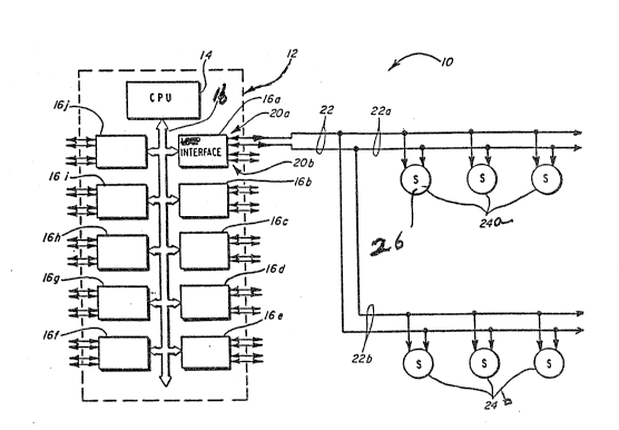
Figure 1 is an overall block diagram
illustrating a detection system in accordance with the
present invention;
2~7~2~0
- 6 -
Figure 2 is a schematic illustrating a
portion o~ one of ~he detectors or ffensors of the
syst~m o~ Figure l;
Fi~ure 3 is a linearized plot of output
voltage versus lev~l of smoke for khe detector of
Figure 2;
Figure 4 is a standardized plot illustrating
output voltage versus smoke or current flow for a
detector u~eable with the ~ystem of Figure 1; and
Figur~ 5 is ~ flow diagram illustrating a
threshold determination in accordance with th~ present
invention.
Detaile~ De~ri~tlon o~ the Pr~err~ ~b~di~e~t~
While this invention is ~usceptible o~
embodiment in many different form~, there are shown in
the drawing and will be described herein in detail
specific e~bodiments thereof with the understanding
that the pr~sent disclosure is to be considered as an
exemplification of the principles of the invention and
is not intended to limit the invention o the specific
embodiments illustrat~d.
Figure 1 illustrates a system 10 of the kype
useable with the present inventio~. The system 10
includes a control unit 12 which would be located in
the vicinity of a central control panel.
The control unit 12 includes a programmable
central processing unit 14. The processing unit 14 can
be a commercially available microcomputer.
The proc~ssing unit 14 is coupled via a
bidirectional data and address bUs 16 to a plurality of
communications line interfac~s 16a through 16j. Each
of the interfaces, such as the interf~e 16a include~
dual input~output port~, such as the ports 20a and 20b.
Each of the input port~, such as input/output
port 20a can be coupled to a bidirectional
2~7~2~
communications line 22. The li~e 22 can be split into
two segments, ~or example, 22a and 22b.
Coupled to each of the s~ments 22a and 22b
is a plurality o~ detectors or sensors 24a and 24b
respectively. ~ach of the detectors or ensors, uch
as the detector 26, can be a combustion products
detector such as an ionization-type or a photoelectric-
type smoke datector. It will be understood that other
types of detectors or sensors could be used with the
system 10 without departing from the spirit or scope of
the present invention.
The detector 26 can receive commands from the
control unit 12 via the bidirectional lines 22.
Similarly, the detector 26 can return information
indicative of a detected ambient condition such as
smoke level or temperature.
Figure 2 is a portion of a schematic of an
ion-type detector, such as the detector 26, usable in
the system 10. The detector 26 includes a two-part
cha~ber 30. The chamber 30 in d udes a re~erence
chamber 32 and an active chamber 34.
Chamb~r 32 is coupled to a source, Vdd.
Chamber 34 is connected to a node CT.
The node CT is in a voltage divider formed of
resistors 36, 38. A second node CI is between resistor
36 and a remote test input 40. A positive going signal
on the line 40, initiated by a "test" command from the
cantral panel 12 causes the detector 26 to go into a
test condition.
In a normal clear air state essentially zero
current flows through thQ chamber 30. The voltage at
node CT is essentially zero as the impedance across the
chamber 30 i~ very high - hundreds o meg. ohms.
As is conventional in ion chambers, a center
electrode 42 provides a variable voltage output, CEV in
~7~260
- 8 -
response to conditions in the active chamber 34. In
clear air, the output voltage CEV i5 essentially aqual
to b*Vdd. ~he constant b is set by the physical ~hamber
characteristics.
When a te~t is initiated, via the remote test
input ~0 or local tes~ ~witch 40a, a voltage Vdd is
applied to node CI ~ A test voltage of
220/(220+63)*(Vdd~.6) is applied to node CT and eguals
~722 Vdd ~or the illustrated resistor values.
In response to the applied test voltage, the
output voltage from electrode 42 increases to:
CETEST = ~ (Vdd -- CT) +CT
= b(Vdd-.722 Vdd)+.722 V~d
The output test voltage from electrode 42 is
dependent on Vdd, b, and the ratio of resistors 36, 3g.
The value~ of resistors 36, 38 have been chosen as
representative of the output ~rom chamber 30 in
response to the presence of some nominal degree of
smoke. However, no particular ratio is required.
Different resistance ratios could be used,
since no ~pecific smoke condition is required. The
disclosed values, 68K n for resistor 36, and 220K n for
resistor 38, preferably will be the ~ame for all ion
detector~ in the pluralities 24a, 24b.
The output from the electrode 42 is buffered
in a unity gain, non-inverting operational ampli~ier
50. Output from the amplifier 50, on a line 52 is at
a substantially lower impedance than the output
impedance of the chamber 30.
The output voltage on line 52 is applied via
a reverse hiased Zener diode 54 to a voltage divider
formed of potentiometer 56 and fixed resistor 58. A
divided analog output voltage level on a line 60 has an
~5 amplitude corresponding to the condition of the chamber
10 .
2 ~ ~
g
The analog vvltage on the line 60 is
converted in a voltage-to-pulse converter 62 to a
corresponding pulse width on a line ~4. The c1etector
output, on the line 64 is a sequence of pulse widths.
The pulse width on the line 64 is related to input
voltage on the line 60 by a constant c ~sec/voltO
The output on the line 64 can be coupled by
interface circuitry 66 to ths bidirectional
co~munication lines 22a. The control unit 12 can khen
sense the value on the lines 22 ~rom the detector 26
indicative of the ambient condition thereat.
The clear air output voltage on the line 42
of detector 26 can be expressed as a pulse width by:
CA=C(~EV-vz~=~(h*vdd-vz3o
The output voltage on the line 4~ when the
detector 26 is in the test mode can be expressed as a
pulse width by:
T-c*(.722 Vdd+.278*b*Vdd Vz)-
Figure 3 illustrates a linearized plot of
chamber output voltage, VOUT~ as measured at the output,
line 42, of the dekector of Figure 2 vs. "Smoke."
Detectors of the type in Figure 2 will normally operate
in a range between the clear air point, CA, and the
test point, TEST, of Figure 3.
The clear air output pulse width can be
measured at the control unit 12. This corresponds ~o
a particular pulse width that is stored for the
respective detector by the processor unit 14.
The test value output pulse width of the
detector 26 is then contemporaneously measured. This
value is also stored by the processor unit 14.
The slope of the line between the clear air
output pulse width CA and the test output pulse width
T can be derived from the equations for the detector.
2~2~0
-- 10 -
That slope is the same as the conskant "c" and i~ egual
to:
c = (~- 27~*C~) ~s~c/volt
(~7~*(Vdd-Vz)
where Vdd=10.5 volts and Vz=3.3 ~olt.
By measuring the clear air output, CA, in
~sec and the test condition output, T, in ~sec, at
essentially the same time, the slope c of a line
joining those two points can b~ obtained using the
above equation~ Then, the incremental output voltage
change ~V for an intermediate smoke condition, "x" such
as measured during normal operation can be determined
at the panel:
c*(~V)~sec = x-CA
where x = c*(~V)+CA ~sec.
Thus, without any knowledge as to the level
of smoke density in the chamber that the test condition
corresponds to, if the value of "x" ~sec can be
calculated for a particular ~V in the chamber, then "x~'
can be set as an alarm threshold particular to that
detector if related somehow to a level of smoke in the
chamber.
The above described method or process can be
combined with a physical constant of the chamber common
to all detectors of the pluralities 24a, 24b. The
constant is based on a graph sf output voltage, V0~,
vs. current I of the chamber 30 in a standardized smoke
box for various smoke conditions as plotted in Figure
4. The graph of Figure 4 is measured off of a
detector, such as th~ detector 26 of Figure 2 located
in a smoke box.
Detector output voltage, is plotted in Figure 4
as a function of smoke density in the box. The smoke
density is indicated by the current flowing in an
2~2~
-- 11 ~
indicating chamber in the box. The current flow varies
from 100 pa in clear air, to zero curr~nt at 100
smoke.
In a clear air condition, corresponding to
100 pA in the chamber for the smo~e box, the detector
26 has a voltage output of approximately half the
internal power supply vol~age. As the smoke is
increased in the smoke box, the smoke box chamber
current decreases and gives a measuremen~ of the level
of smoke in pico amps. At the same time, the voltage
in the chamber of the detector 26 wh~n tested in the
box i~ increasing with the level of smoke.
In the linear region, the output voltage of
the detector 26, Vcev, is related to the smoke box
chamber current by a constant, 17 pA/volt. The slope
in the linear region is 1/17 volt/pA.
The desired position L on th~ graph in pico
amps can be related to a corresponding change in
chamber output voltage by:
~V _ loo-L
where L is a value o~ smoke box chamber current
corresponding to an alarm level of smoke. ~his can be
a constant for all detectors in the pluralities 24a,
24b. Alternately, a different L threshold valuP could
be selected for different detectors. The voltage
variation and output pulse width variation are related
by:
(~V)* c~sec/volts = ~sec
where ~sec corresponds to a change in output pulse
width ~rom that of clear air, needed to achieve a
desired alarm lev01 or threshold as determined by L (in
pico amps).
The above relationships depend on the
previously noted constant o~ 17pa/volt which is a
2 ~ ~
- 12 ~
common, storable characteristic o~ the detectors in the
pluralitie~ 24a, 24bo Once the variation, for a given
L threshold value, is known then the alarm level AL in
microseconds can be determined by.
AL = CA ~ ~sec.
A pulsa width ~rom the detector 26 that
equals or exceeds ~L is an alarm condition. Thus, in
the control unit ~2 it is only necessary to compare a
returned pulse width to the calculated and prestored
alarm threshold AL.
The value of c for a given value of clear air
(CA) and test ~T) in microseconds as noted previously,
can be determined from:
c = _(T=.278*CA~
~722*(Vdd-Vz)
The test output value can vary over time with
respect to a given unitO So can the clear air value.
However, by remeasuring both from time to time, the
alarm level can be regularly recalculated if de~ired.
As an example, for a measured detector,
CA = 438 ~sec
T - 1,474 ~sec
c = (T-.278*CA)__
(.722)*(Vdd-Vz)
= 260 ~sec/volt
assuming that the desired threshold L level should
e~ual 57.5 pa. Then~
~V = 100 57.5 pa = 2.5 volts
17pa/volt
This is the variation, ~V, from clear air,
for the selected current threshold, L, for all ion-type
detectors, members of the pluralities 24a, 24b. This
value can be calculated once and storedO Then,
2 ~ ~
- 13 -
~ec = c*~V - 260*2.5
= 650 ~sec
As a result, the calculated alarm threshold AL ~or this
particular detector should be set at:
AL = CA + ~s~c
= 43~ ~sec + 650 ~sec.
once the calculated alarm level AL is known,
that value is stored at the control unit 12. The pulse
widths of data returned ~rom a selected detector need
only be compared to the prestored re~pective value of
AL to determine if the detector is indicating an alarm
condition.
Non-linearties can be minimized using an
empirically derived coxrection ~actor applied to each
calculated value of AL. This factor, f, is determined
from:
f = abs. value o~ [.l*(AL~(SV-
2.5}*c+2,000)~]
ALCORRECTED AL f
Given a previously calculated and stored
alarm threshold, AL, the current detector location
(current sensitivity) on the curve of Figure 4 can be
estimated by the following e~uation.
17
L = 100 ~ c *tAL-cAc] P a~p
In the above equation, CAC represents a
current value of clear air read back from the sub~ect
detector such as the detector 26. c is deter~ined
based on the current test value Tc. The calculated L
value can be displayed at the control unit 14 for an
operator to see. Alternately, the L value, the
sensitivity o~ the det0ctor, can be used to determine
when to initiake a recalculation of the AL threshold.
2 ~ 7 ~ 2 6 O
Alternately, the sensitivity could be
displayed at other locations. For example,
sensitivity, as well s other information, could be
displayed at a remote terminal.
Figure 5 illustrates a flow diagram of the
method of determining an alarm level or threshold for
the detector 26. In a step ~0, the process is
initiated by selecting a detector. The clear air
return value from the selected detector is sensed at
the control unit 12 in a step 82. The control unit 12
then commands the selected det2ctor to enter its test
mode. The returned test value ~rom the selected
detector is sensed at the control unit 12 and stored in
a step 84.
In a step 86, the control unit determines a
value for c based on the pre~iously measured and stored
values for clear air and the test condition in a step
~6. In a step 88, the control unit retrieves a common
prestored parameter variation value ~V. This
corresponds to the expected variation of the chamber
output voltage ~rom clear air in response to the
presence o~ a predetermined smoke level.
Using the value o~ ~V re~rieved in the s~ep
88, the value of ~sec is determined in a skep 90.
Subsequently, in a step 92 the value o~ the alarm level
or threshold AL can then be determined. The determined
alarm level or threshold is stored in a step 94 at the
control unit 12 for subsequent use. Using the above-
described proceRs, a thre~hold or alarm level can be
determined uniquely for each detector in the
pluralities 24a and 24b.
Subsequently, to determine whether or not a
selected detector, such as the detector 26, is
exhibiting an alarm condition, the current ambient
condition being sensed at the detector,
2 0 ~ ~ 2 ~ ~
repressntation of which is then transmitted to the
control unit 12, is compared ~o ~he predete~mined alarm
level or threshold. If the current ~mbient
representation exceeds the predetermined alarm
threshold ~he control unit ~2 can place the system into
alarm 2
The above-described comparison process can be
repeated and the results averaged out over several
trials to minimize false alarmsO Further, if desired,
the alarm level can be redetermined on a regular or
intermittent basis depending on the environmental
circumstances of the alarm system 10.
From the foregoing, it will be observed that
numerous variations and modifications may be effected
without departing ~rom the spirit and scope of the
inv~ntion. It is to be understood that no limitation
with respect to the specific apparatus illustrated
herein is intended or should be inferred. It is~ of
course, intended to cover by the appended claims all
such modifications as ~all within the scope of the
claims.