Language selection

Search

Patent 2075283 Summary

Third-party information liability

Some of the information on this Web page has been provided by external sources. The Government of Canada is not responsible for the accuracy, reliability or currency of the information supplied by external sources. Users wishing to rely upon this information should consult directly with the source of the information. Content provided by external sources is not subject to official languages, privacy and accessibility requirements.

Claims and Abstract availability

Any discrepancies in the text and image of the Claims and Abstract are due to differing posting times. Text of the Claims and Abstract are posted:

  • At the time the application is open to public inspection;
  • At the time of issue of the patent (grant).
(12) Patent: (11) CA 2075283
(54) English Title: IMPROVED SEAL RING FOR OPEN HEAD DRUM
(54) French Title: COLLIER DE FERMETURE AMELIOREE POUR FUT A OUVERTURE TOTALE
Status: Expired and beyond the Period of Reversal
Bibliographic Data
(51) International Patent Classification (IPC):
  • B65D 45/32 (2006.01)
(72) Inventors :
  • KUSTA, FRED A. (United States of America)
(73) Owners :
  • SELF INDUSTRIES, INC.
(71) Applicants :
  • SELF INDUSTRIES, INC. (United States of America)
(74) Agent: SMART & BIGGAR LP
(74) Associate agent:
(45) Issued: 1996-12-03
(86) PCT Filing Date: 1990-04-06
(87) Open to Public Inspection: 1991-08-07
Examination requested: 1992-08-04
Availability of licence: N/A
Dedicated to the Public: N/A
(25) Language of filing: English

Patent Cooperation Treaty (PCT): Yes
(86) PCT Filing Number: PCT/US1990/001806
(87) International Publication Number: US1990001806
(85) National Entry: 1992-08-04

(30) Application Priority Data:
Application No. Country/Territory Date
475,746 (United States of America) 1990-02-06

Abstracts

English Abstract


A closure ring (11) for use with an open head drum (11) utilizes a reduced diameter portion (26) proximal each end thereof
to increase the force required to draw the end of the ring together about the drum head and an associated lid (16) and gasket (13),
thereby increasing the compressive force applied to the gasket (13) in the reduced diameter region resulting in greater sealing ef-
fect at the junction of the ring ends (18, 19).


Claims

Note: Claims are shown in the official language in which they were submitted.

What I claim is:
1. An improved ring for securing and sealing a lid to
an open head drum, said drum having an outwardly extending
upper edge and said lid having an annular seat formed
thereon for engagement on said upper edge, said seat urging
a compressible gasket against said upper edge to form a
seal, characterized by the combination therewith of a
circular member split on one radian thereof to form a pair
of adjacent ends, said circular member having a concave
inner surface for encasing the outer peripheral portion of a
lid and the upper edge of an open head drum, and means for
urging said adjacent ends toward each other, each of said
adjacent ends having a radially projecting reduced diameter
portion.
2. An improved ring as defined in claim 1 wherein
said concave inner surface is further characterized by
an average diameter substantially equal to or less than the
outer diameter of said lid.
3. An improved ring as defined in claim 2 wherein
said reduced diameter portion of each end forms an inwardly
projecting shoulder transversely of said concave surface.
4. An improved ring as defined in claim 3 wherein
said reduced diameter portion includes a semi-conical
surface tapering from said inwardly projecting shoulder
toward the end of said circular member to form a minimum
diameter at the end of said circular member.
5. A ring for sealing a lid to an open headed drum or
the like wherein said drum has an outwardly rolled upper

edge and said lid has an annular seat formed thereon to rest
on said upper edge with an annular gasket intermediate said
lid and drum, characterized by a substantially split ring
having a first end and a second end with a means for
securing said ends to one another, and an inwardly opening
groove extending substantially the length of said split ring
for receiving a lid, gasket, and upper edge of a drum
therein, and a first radially inwardly extending protuberance formed on said
groove proximal said first end and a second radially
inwardly extending protuberance formed proximal said second
end, said protuberances being parallel when said first and
second ends are abutted.
6. A sealing ring as defined on claim 5 further
characterized in that said first and second protuberances
are radial ribs which are perpendicular to said sealing
ring, said ribs being conical on their inner surfaces having
a minimum diameter at said first and second ends.
7. A sealing ring for use with an open top drum or
the like, said drum having an outwardly rolled upper edge, a
lid having a annular portion adapted for engagement with at
least part of the upper surface of said rolled upper edge
and an annular gasket for sealing said drum and lid,
comprising a split ring having an inner diameter sufficient
to permit it to encircle said upper edge and gasket, and
forming a radially inwardly opening retainer for said upper
edge, lid and gasket, said split ring having a reduced
diameter portion proximal each end thereof and means for

- 8 -
urging said ends of said ring toward an abutting relationship
when encircling said upper edge, lid, and gasket whereby said
gasket undergoes maximum compression in the region beneath said
reduced diameter portion.
8. An improved ring as defined in claim 2 wherein said
reduced diameter portion is characterized by a semi-conical
surface tapering toward the end of said circular member to form
a minimum diameter at the end of said circular member.
9. An improved ring as defined in claim 7 wherein said
reduced diameter portion is characterized by a semi-conical
surface tapering toward the end of said split ring to form a
minimum diameter at the end of said split ring.
10. A sealing ring as in claim 7 wherein said split ring
has a concave inner surface.
11. An improved ring as defined in claim 1 wherein said
concave inner surface has an average diameter substantially equal
to or less than the outer diameter of said lid.

Description

Note: Descriptions are shown in the official language in which they were submitted.


WO91/12184 PCT/US90/01806
2075283
IMPROVED SEAL RING FOR OPEN HEAD DRUM
Techical Field
The present invention relates to the field of reusable
containers and more specifically to reusable drums commonly
known as open head drums. More particularly the present
invention relates to an improvement in sealing open head
drums and in even greater particularity relates to an
improvement in the closure ring used to secure a lid to an
open head drum.
Background Art
Open head drums are commonly used as storage and
transportation containers in many industries in the U.S. and
Europe. Such drums are relatively easy to clean or
recondition and thus are generally reusable. One problem
that open head drums have is the difficulty in forming a
proper seal about the top of the drum. Typically, open head
drums have an outwardly rolled upper edge which is engaged
by a lid which has an annular seat formed thereon. The seat
rests atop a gasket intermediate the drum and the lid. A
closure ring is placed over the lid and drum rim and
tightened to maintain the sealing pressure on the gasket.
The closure ring is a split ring which is secured on the
drum head by one of various means for urging the ends of the
ring toward each other. The weakness in the seal lies at
the junction of the split ring. Open head drums must
undergo drop tests wherein the drums are dropped from a
height of four feet. The internal and external forces
`~L

W O 91/12184 2 0 7 ~ 2 8 3 PC~r/US90/01806
gene-ra~ed by the sudden deceleration upon impact typica~y
cause leakage at the junction. Prior attempts to alleviate
the problem have been to reinforce the lid at the junction
as in U.S. Patent 4,646,931 or to place a protective cover
over the junction as in U.S. Patent 3,587,700. Neither
attempt has been successful, thus there remains a need for a
closure ring which reduces the vulnerability of the seal at
the ring junction.
Summary of the Invention
It is the object of the present invention to reduce the
vulnerability of open head drums to leaks in the seal formed
between the drums and the lids thereof.
A further object of the invention is to prevent leakage
of a sealed open head drum subjected to a standard drop
test.
Each of the foregoing objects is to further the
principal object of improving the reliability and usefulness
of open head drums as sealed containers.
Each of the foregoing objects and other advantages are
accomplished in my invention which applies greater pressure
to the lid and gasket at the end of the split ring thereby
improving the seal in the region of the junction. The
mechanism used to accomplish this improved seal is a reduced
diameter region at each of the split ends. As the ends are
urged together greater radial pressure must be applied to
the lid to reduce the separation between the ends, therefore
the force applied to the lid and gasket is increased.

~0752~3
W O 91/12184 PC~r/US90/01806
3 . .
- Brief Descrition of the Drawinqs
A sealing ring embodying the features of my invention
is depicted in the accompanying drawing which form a portion
of this disclosure and wherein:
FIG. 1 is a perspective exploded view of an open head,
drum, lid, gasket, and closure ring;
FIG. 2 is a sectional view of the closure ring taken
through the end portion;
FIG. 3 is an end view of the closure ring taken along
the split of the ring; and
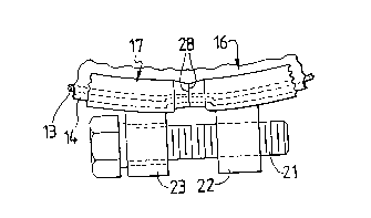
FIG. 4 is a partial top view of the closure ring.
Description of the Best Mode
Referring to the drawings for a clearer understanding
of my invention it may be seen from FIG. 1 that an open head
drum 11 has an upper peripheral edge 12 which may be formed
into an outwardly rolled rim. A compressible gasket 13 is
typically placed between the upper edge 12 and a downwardly
opening annular seat 14 formed in a lid 16. When a drum 11
is to be sealed, normally the lid 16 will be urged into
position by a fluid activated ram which compresses the
gasket 13 as it seats the lid 16 on the drum. The lid 16 is
then secured by a closure ring 17.
My improved closure ring 17 is a split ring having a
first end 18 and a second end 19, the ends are normally
connected by a threaded bolt 21 which engages a threaded eye
22 on one end and passes through an unthreaded eye 23 on the
other and such that rotation of the threaded bolt 21 draws
the two ends toward abutment. It will be understood by

WO91/12184 PCT/US90/01806
2 O7 S~ 83 4
those ~amiliar with the art that various other means may be
used to draw the ends together.
My ring forms an inwardly opening receptacle into which
the upper edge 12, seat 14, and gasket 13 may be received.
Typically the receptacle forms a concave surface 24, the
inner diameter of which is equal to or substantially equal
to the outer diameter of the lid 16, except in my invention,
a reduced diameter portion 26 is formed proximal each end of
the split ring. The reduced diameter portion is a radially
inwardly extending protrusion which forms a shoulder 27
transverse to the concave surface such that the protrusions
formed on each end form a pair of paralleled shoulders 28
where the ends abut. Each reduced diameter portion 26 also
has a conical surface 29 extending from the shoulder 27 to
the terminal end of the ring, thus forming a minimum
diameter at the adjacent ends of the split ring.
It will be appreciated by those familiar with the art
that, when a conventional ring is drawn tightly about the
drum and lid, substantially uniform forces are applied to
the lid except at the adjacent ends of the ring, where the
force is somewhat less than at other points about the ring.
With my invention, as the ring is urged into a closed
position the inward projection at each end must be overcome
to tighten the ring, thus applying greater pressure at the
adjacent ends of the ring than at other points about the
ring. This pressure serves to hold the lid more firmly
against the gasket in the region thus insuring the

W091/12184 207~8~ PCT/US90/0l806
compression of the gasket and hence its resistance to leak.
Therefore, when the drum is subjected to stresses, such as
during the drop test, the path of least resistance to fluid
escape through the junction of the ring is eliminated by the
compressed gasket beneath the reduced diameter portion of
the ring.
While I have shown my invention in one form, it will be
obvious to those skilled in the art that it is not so
limited but is susceptible of various changes and
modifications without departing from the spirit thereof.

Representative Drawing
A single figure which represents the drawing illustrating the invention.
Administrative Status

2024-08-01:As part of the Next Generation Patents (NGP) transition, the Canadian Patents Database (CPD) now contains a more detailed Event History, which replicates the Event Log of our new back-office solution.

Please note that "Inactive:" events refers to events no longer in use in our new back-office solution.

For a clearer understanding of the status of the application/patent presented on this page, the site Disclaimer , as well as the definitions for Patent , Event History , Maintenance Fee  and Payment History  should be consulted.

Event History

Description Date
Time Limit for Reversal Expired 2003-04-07
Letter Sent 2002-04-08
Inactive: Late MF processed 2001-04-20
Inactive: Late MF processed 1999-04-26
Letter Sent 1999-04-06
Inactive: Adhoc Request Documented 1998-04-06
Letter Sent 1997-04-07
Grant by Issuance 1996-12-03
Request for Examination Requirements Determined Compliant 1992-08-04
All Requirements for Examination Determined Compliant 1992-08-04
Application Published (Open to Public Inspection) 1991-08-07

Abandonment History

There is no abandonment history.

Fee History

Fee Type Anniversary Year Due Date Paid Date
MF (patent, 8th anniv.) - standard 1998-04-06 1998-03-18
MF (patent, 9th anniv.) - standard 1999-04-06 1999-04-26
Reversal of deemed expiry 2001-04-06 1999-04-26
MF (patent, 10th anniv.) - standard 2000-04-06 2000-03-16
Reversal of deemed expiry 2001-04-06 2001-04-20
MF (patent, 11th anniv.) - standard 2001-04-06 2001-04-20
Owners on Record

Note: Records showing the ownership history in alphabetical order.

Current Owners on Record
SELF INDUSTRIES, INC.
Past Owners on Record
FRED A. KUSTA
Past Owners that do not appear in the "Owners on Record" listing will appear in other documentation within the application.
Documents

To view selected files, please enter reCAPTCHA code :


To view images, click a link in the Document Description column (Temporarily unavailable). To download the documents, select one or more checkboxes in the first column and then click the "Download Selected in PDF format (Zip Archive)" or the "Download Selected as Single PDF" button.

List of published and non-published patent-specific documents on the CPD .

If you have any difficulty accessing content, you can call the Client Service Centre at 1-866-997-1936 or send them an e-mail at CIPO Client Service Centre.

({010=All Documents, 020=As Filed, 030=As Open to Public Inspection, 040=At Issuance, 050=Examination, 060=Incoming Correspondence, 070=Miscellaneous, 080=Outgoing Correspondence, 090=Payment})


Document
Description 
Date
(yyyy-mm-dd) 
Number of pages   Size of Image (KB) 
Abstract 1995-08-16 1 46
Claims 1994-06-10 3 137
Drawings 1994-06-10 1 38
Description 1994-06-10 5 235
Abstract 1996-12-02 1 42
Description 1996-12-02 5 166
Drawings 1996-12-02 1 33
Claims 1996-12-02 3 108
Representative drawing 1999-01-12 1 5
Maintenance Fee Notice 1999-05-03 1 179
Late Payment Acknowledgement 1999-05-16 1 172
Late Payment Acknowledgement 2001-04-26 1 171
Maintenance Fee Notice 2002-05-05 1 179
Fees 1998-03-17 1 34
Fees 1999-04-25 1 39
Fees 1997-04-06 1 31
Fees 1996-02-13 1 30
Fees 1995-03-26 1 39
Fees 1994-04-04 1 50
Fees 1993-03-04 1 31
Fees 1992-08-03 1 46
Fees 1994-04-28 1 28
Examiner Requisition 1994-06-19 2 67
Prosecution correspondence 1994-12-19 3 98
PCT Correspondence 1996-09-24 1 38
Courtesy - Office Letter 1996-04-21 1 20
PCT Correspondence 1996-03-31 2 67
Courtesy - Office Letter 1993-11-08 1 20
PCT Correspondence 1992-12-06 2 65
Courtesy - Office Letter 1993-07-26 1 22
Courtesy - Office Letter 1993-08-16 1 25
Courtesy - Office Letter 1992-10-18 1 33
International preliminary examination report 1992-08-03 22 739
PCT Correspondence 1992-12-06 1 48
PCT Correspondence 1993-09-28 3 117
PCT Correspondence 1993-05-25 2 67