Sélection de la langue

Search

Sommaire du brevet 2075283 

Énoncé de désistement de responsabilité concernant l'information provenant de tiers

Une partie des informations de ce site Web a été fournie par des sources externes. Le gouvernement du Canada n'assume aucune responsabilité concernant la précision, l'actualité ou la fiabilité des informations fournies par les sources externes. Les utilisateurs qui désirent employer cette information devraient consulter directement la source des informations. Le contenu fourni par les sources externes n'est pas assujetti aux exigences sur les langues officielles, la protection des renseignements personnels et l'accessibilité.

Disponibilité de l'Abrégé et des Revendications

L'apparition de différences dans le texte et l'image des Revendications et de l'Abrégé dépend du moment auquel le document est publié. Les textes des Revendications et de l'Abrégé sont affichés :

  • lorsque la demande peut être examinée par le public;
  • lorsque le brevet est émis (délivrance).
(12) Brevet: (11) CA 2075283
(54) Titre français: COLLIER DE FERMETURE AMELIOREE POUR FUT A OUVERTURE TOTALE
(54) Titre anglais: IMPROVED SEAL RING FOR OPEN HEAD DRUM
Statut: Périmé et au-delà du délai pour l’annulation
Données bibliographiques
(51) Classification internationale des brevets (CIB):
  • B65D 45/32 (2006.01)
(72) Inventeurs :
  • KUSTA, FRED A. (Etats-Unis d'Amérique)
(73) Titulaires :
  • SELF INDUSTRIES, INC.
(71) Demandeurs :
  • SELF INDUSTRIES, INC. (Etats-Unis d'Amérique)
(74) Agent: SMART & BIGGAR LP
(74) Co-agent:
(45) Délivré: 1996-12-03
(86) Date de dépôt PCT: 1990-04-06
(87) Mise à la disponibilité du public: 1991-08-07
Requête d'examen: 1992-08-04
Licence disponible: S.O.
Cédé au domaine public: S.O.
(25) Langue des documents déposés: Anglais

Traité de coopération en matière de brevets (PCT): Oui
(86) Numéro de la demande PCT: PCT/US1990/001806
(87) Numéro de publication internationale PCT: US1990001806
(85) Entrée nationale: 1992-08-04

(30) Données de priorité de la demande:
Numéro de la demande Pays / territoire Date
475,746 (Etats-Unis d'Amérique) 1990-02-06

Abrégés

Abrégé anglais


A closure ring (11) for use with an open head drum (11) utilizes a reduced diameter portion (26) proximal each end thereof
to increase the force required to draw the end of the ring together about the drum head and an associated lid (16) and gasket (13),
thereby increasing the compressive force applied to the gasket (13) in the reduced diameter region resulting in greater sealing ef-
fect at the junction of the ring ends (18, 19).

Revendications

Note : Les revendications sont présentées dans la langue officielle dans laquelle elles ont été soumises.


What I claim is:
1. An improved ring for securing and sealing a lid to
an open head drum, said drum having an outwardly extending
upper edge and said lid having an annular seat formed
thereon for engagement on said upper edge, said seat urging
a compressible gasket against said upper edge to form a
seal, characterized by the combination therewith of a
circular member split on one radian thereof to form a pair
of adjacent ends, said circular member having a concave
inner surface for encasing the outer peripheral portion of a
lid and the upper edge of an open head drum, and means for
urging said adjacent ends toward each other, each of said
adjacent ends having a radially projecting reduced diameter
portion.
2. An improved ring as defined in claim 1 wherein
said concave inner surface is further characterized by
an average diameter substantially equal to or less than the
outer diameter of said lid.
3. An improved ring as defined in claim 2 wherein
said reduced diameter portion of each end forms an inwardly
projecting shoulder transversely of said concave surface.
4. An improved ring as defined in claim 3 wherein
said reduced diameter portion includes a semi-conical
surface tapering from said inwardly projecting shoulder
toward the end of said circular member to form a minimum
diameter at the end of said circular member.
5. A ring for sealing a lid to an open headed drum or
the like wherein said drum has an outwardly rolled upper

edge and said lid has an annular seat formed thereon to rest
on said upper edge with an annular gasket intermediate said
lid and drum, characterized by a substantially split ring
having a first end and a second end with a means for
securing said ends to one another, and an inwardly opening
groove extending substantially the length of said split ring
for receiving a lid, gasket, and upper edge of a drum
therein, and a first radially inwardly extending protuberance formed on said
groove proximal said first end and a second radially
inwardly extending protuberance formed proximal said second
end, said protuberances being parallel when said first and
second ends are abutted.
6. A sealing ring as defined on claim 5 further
characterized in that said first and second protuberances
are radial ribs which are perpendicular to said sealing
ring, said ribs being conical on their inner surfaces having
a minimum diameter at said first and second ends.
7. A sealing ring for use with an open top drum or
the like, said drum having an outwardly rolled upper edge, a
lid having a annular portion adapted for engagement with at
least part of the upper surface of said rolled upper edge
and an annular gasket for sealing said drum and lid,
comprising a split ring having an inner diameter sufficient
to permit it to encircle said upper edge and gasket, and
forming a radially inwardly opening retainer for said upper
edge, lid and gasket, said split ring having a reduced
diameter portion proximal each end thereof and means for

- 8 -
urging said ends of said ring toward an abutting relationship
when encircling said upper edge, lid, and gasket whereby said
gasket undergoes maximum compression in the region beneath said
reduced diameter portion.
8. An improved ring as defined in claim 2 wherein said
reduced diameter portion is characterized by a semi-conical
surface tapering toward the end of said circular member to form
a minimum diameter at the end of said circular member.
9. An improved ring as defined in claim 7 wherein said
reduced diameter portion is characterized by a semi-conical
surface tapering toward the end of said split ring to form a
minimum diameter at the end of said split ring.
10. A sealing ring as in claim 7 wherein said split ring
has a concave inner surface.
11. An improved ring as defined in claim 1 wherein said
concave inner surface has an average diameter substantially equal
to or less than the outer diameter of said lid.

Description

Note : Les descriptions sont présentées dans la langue officielle dans laquelle elles ont été soumises.

WO91/12184 PCT/US90/01806
2075283
IMPROVED SEAL RING FOR OPEN HEAD DRUM
Techical Field
The present invention relates to the field of reusable
containers and more specifically to reusable drums commonly
known as open head drums. More particularly the present
invention relates to an improvement in sealing open head
drums and in even greater particularity relates to an
improvement in the closure ring used to secure a lid to an
open head drum.
Background Art
Open head drums are commonly used as storage and
transportation containers in many industries in the U.S. and
Europe. Such drums are relatively easy to clean or
recondition and thus are generally reusable. One problem
that open head drums have is the difficulty in forming a
proper seal about the top of the drum. Typically, open head
drums have an outwardly rolled upper edge which is engaged
by a lid which has an annular seat formed thereon. The seat
rests atop a gasket intermediate the drum and the lid. A
closure ring is placed over the lid and drum rim and
tightened to maintain the sealing pressure on the gasket.
The closure ring is a split ring which is secured on the
drum head by one of various means for urging the ends of the
ring toward each other. The weakness in the seal lies at
the junction of the split ring. Open head drums must
undergo drop tests wherein the drums are dropped from a
height of four feet. The internal and external forces
`~L

W O 91/12184 2 0 7 ~ 2 8 3 PC~r/US90/01806
gene-ra~ed by the sudden deceleration upon impact typica~y
cause leakage at the junction. Prior attempts to alleviate
the problem have been to reinforce the lid at the junction
as in U.S. Patent 4,646,931 or to place a protective cover
over the junction as in U.S. Patent 3,587,700. Neither
attempt has been successful, thus there remains a need for a
closure ring which reduces the vulnerability of the seal at
the ring junction.
Summary of the Invention
It is the object of the present invention to reduce the
vulnerability of open head drums to leaks in the seal formed
between the drums and the lids thereof.
A further object of the invention is to prevent leakage
of a sealed open head drum subjected to a standard drop
test.
Each of the foregoing objects is to further the
principal object of improving the reliability and usefulness
of open head drums as sealed containers.
Each of the foregoing objects and other advantages are
accomplished in my invention which applies greater pressure
to the lid and gasket at the end of the split ring thereby
improving the seal in the region of the junction. The
mechanism used to accomplish this improved seal is a reduced
diameter region at each of the split ends. As the ends are
urged together greater radial pressure must be applied to
the lid to reduce the separation between the ends, therefore
the force applied to the lid and gasket is increased.

~0752~3
W O 91/12184 PC~r/US90/01806
3 . .
- Brief Descrition of the Drawinqs
A sealing ring embodying the features of my invention
is depicted in the accompanying drawing which form a portion
of this disclosure and wherein:
FIG. 1 is a perspective exploded view of an open head,
drum, lid, gasket, and closure ring;
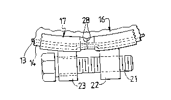
FIG. 2 is a sectional view of the closure ring taken
through the end portion;
FIG. 3 is an end view of the closure ring taken along
the split of the ring; and
FIG. 4 is a partial top view of the closure ring.
Description of the Best Mode
Referring to the drawings for a clearer understanding
of my invention it may be seen from FIG. 1 that an open head
drum 11 has an upper peripheral edge 12 which may be formed
into an outwardly rolled rim. A compressible gasket 13 is
typically placed between the upper edge 12 and a downwardly
opening annular seat 14 formed in a lid 16. When a drum 11
is to be sealed, normally the lid 16 will be urged into
position by a fluid activated ram which compresses the
gasket 13 as it seats the lid 16 on the drum. The lid 16 is
then secured by a closure ring 17.
My improved closure ring 17 is a split ring having a
first end 18 and a second end 19, the ends are normally
connected by a threaded bolt 21 which engages a threaded eye
22 on one end and passes through an unthreaded eye 23 on the
other and such that rotation of the threaded bolt 21 draws
the two ends toward abutment. It will be understood by

WO91/12184 PCT/US90/01806
2 O7 S~ 83 4
those ~amiliar with the art that various other means may be
used to draw the ends together.
My ring forms an inwardly opening receptacle into which
the upper edge 12, seat 14, and gasket 13 may be received.
Typically the receptacle forms a concave surface 24, the
inner diameter of which is equal to or substantially equal
to the outer diameter of the lid 16, except in my invention,
a reduced diameter portion 26 is formed proximal each end of
the split ring. The reduced diameter portion is a radially
inwardly extending protrusion which forms a shoulder 27
transverse to the concave surface such that the protrusions
formed on each end form a pair of paralleled shoulders 28
where the ends abut. Each reduced diameter portion 26 also
has a conical surface 29 extending from the shoulder 27 to
the terminal end of the ring, thus forming a minimum
diameter at the adjacent ends of the split ring.
It will be appreciated by those familiar with the art
that, when a conventional ring is drawn tightly about the
drum and lid, substantially uniform forces are applied to
the lid except at the adjacent ends of the ring, where the
force is somewhat less than at other points about the ring.
With my invention, as the ring is urged into a closed
position the inward projection at each end must be overcome
to tighten the ring, thus applying greater pressure at the
adjacent ends of the ring than at other points about the
ring. This pressure serves to hold the lid more firmly
against the gasket in the region thus insuring the

W091/12184 207~8~ PCT/US90/0l806
compression of the gasket and hence its resistance to leak.
Therefore, when the drum is subjected to stresses, such as
during the drop test, the path of least resistance to fluid
escape through the junction of the ring is eliminated by the
compressed gasket beneath the reduced diameter portion of
the ring.
While I have shown my invention in one form, it will be
obvious to those skilled in the art that it is not so
limited but is susceptible of various changes and
modifications without departing from the spirit thereof.

Dessin représentatif
Une figure unique qui représente un dessin illustrant l'invention.
États administratifs

2024-08-01 : Dans le cadre de la transition vers les Brevets de nouvelle génération (BNG), la base de données sur les brevets canadiens (BDBC) contient désormais un Historique d'événement plus détaillé, qui reproduit le Journal des événements de notre nouvelle solution interne.

Veuillez noter que les événements débutant par « Inactive : » se réfèrent à des événements qui ne sont plus utilisés dans notre nouvelle solution interne.

Pour une meilleure compréhension de l'état de la demande ou brevet qui figure sur cette page, la rubrique Mise en garde , et les descriptions de Brevet , Historique d'événement , Taxes périodiques et Historique des paiements devraient être consultées.

Historique d'événement

Description Date
Le délai pour l'annulation est expiré 2003-04-07
Lettre envoyée 2002-04-08
Inactive : TME en retard traitée 2001-04-20
Inactive : TME en retard traitée 1999-04-26
Lettre envoyée 1999-04-06
Inactive : Demande ad hoc documentée 1998-04-06
Lettre envoyée 1997-04-07
Accordé par délivrance 1996-12-03
Exigences pour une requête d'examen - jugée conforme 1992-08-04
Toutes les exigences pour l'examen - jugée conforme 1992-08-04
Demande publiée (accessible au public) 1991-08-07

Historique d'abandonnement

Il n'y a pas d'historique d'abandonnement

Historique des taxes

Type de taxes Anniversaire Échéance Date payée
TM (brevet, 8e anniv.) - générale 1998-04-06 1998-03-18
TM (brevet, 9e anniv.) - générale 1999-04-06 1999-04-26
Annulation de la péremption réputée 2001-04-06 1999-04-26
TM (brevet, 10e anniv.) - générale 2000-04-06 2000-03-16
Annulation de la péremption réputée 2001-04-06 2001-04-20
TM (brevet, 11e anniv.) - générale 2001-04-06 2001-04-20
Titulaires au dossier

Les titulaires actuels et antérieures au dossier sont affichés en ordre alphabétique.

Titulaires actuels au dossier
SELF INDUSTRIES, INC.
Titulaires antérieures au dossier
FRED A. KUSTA
Les propriétaires antérieurs qui ne figurent pas dans la liste des « Propriétaires au dossier » apparaîtront dans d'autres documents au dossier.
Documents

Pour visionner les fichiers sélectionnés, entrer le code reCAPTCHA :


Pour visualiser une image, cliquer sur un lien dans la colonne description du document (Temporairement non-disponible). Pour télécharger l'image (les images), cliquer l'une ou plusieurs cases à cocher dans la première colonne et ensuite cliquer sur le bouton "Télécharger sélection en format PDF (archive Zip)" ou le bouton "Télécharger sélection (en un fichier PDF fusionné)".

Liste des documents de brevet publiés et non publiés sur la BDBC .

Si vous avez des difficultés à accéder au contenu, veuillez communiquer avec le Centre de services à la clientèle au 1-866-997-1936, ou envoyer un courriel au Centre de service à la clientèle de l'OPIC.

({010=Tous les documents, 020=Au moment du dépôt, 030=Au moment de la mise à la disponibilité du public, 040=À la délivrance, 050=Examen, 060=Correspondance reçue, 070=Divers, 080=Correspondance envoyée, 090=Paiement})


Description du
Document 
Date
(aaaa-mm-jj) 
Nombre de pages   Taille de l'image (Ko) 
Abrégé 1995-08-16 1 46
Revendications 1994-06-10 3 137
Dessins 1994-06-10 1 38
Description 1994-06-10 5 235
Abrégé 1996-12-02 1 42
Description 1996-12-02 5 166
Dessins 1996-12-02 1 33
Revendications 1996-12-02 3 108
Dessin représentatif 1999-01-12 1 5
Avis concernant la taxe de maintien 1999-05-03 1 179
Quittance d'un paiement en retard 1999-05-16 1 172
Quittance d'un paiement en retard 2001-04-26 1 171
Avis concernant la taxe de maintien 2002-05-05 1 179
Taxes 1998-03-17 1 34
Taxes 1999-04-25 1 39
Taxes 1997-04-06 1 31
Taxes 1996-02-13 1 30
Taxes 1995-03-26 1 39
Taxes 1994-04-04 1 50
Taxes 1993-03-04 1 31
Taxes 1992-08-03 1 46
Taxes 1994-04-28 1 28
Demande de l'examinateur 1994-06-19 2 67
Correspondance de la poursuite 1994-12-19 3 98
Correspondance reliée au PCT 1996-09-24 1 38
Courtoisie - Lettre du bureau 1996-04-21 1 20
Correspondance reliée au PCT 1996-03-31 2 67
Courtoisie - Lettre du bureau 1993-11-08 1 20
Correspondance reliée au PCT 1992-12-06 2 65
Courtoisie - Lettre du bureau 1993-07-26 1 22
Courtoisie - Lettre du bureau 1993-08-16 1 25
Courtoisie - Lettre du bureau 1992-10-18 1 33
Rapport d'examen préliminaire international 1992-08-03 22 739
Correspondance reliée au PCT 1992-12-06 1 48
Correspondance reliée au PCT 1993-09-28 3 117
Correspondance reliée au PCT 1993-05-25 2 67