Note: Descriptions are shown in the official language in which they were submitted.
2~7~3~
FIRE PROTECTION SY~TEM FOR RURAL UNHEATED STRUCTURES
BACKGROUI\ID OF THE INVENTION
5 1. Field of the Invention
The invention relates to fire protection systems for rural unheated builcling,
particularly those housin~ live stock.
2. Description of the Related Art
The need for fire protection of horses and other live stock in a barn is well known.
10 The open stud construction, the availability of an abundance of combustibles and the
lack of minimal fire protection construction techniques such as firestops results in such
structures being at extreme fire risk. In fact, a fire in a barn can completely engulf the
structure and kill the trapped animals in a matter of only seconds. Yet, despite the
danger, the high value of the anirnals, and frequently, the owner's emotional attachment
15 to their horses and other stock, most barns do not have sprinkler systems due to the high
cost of providing such protection and unavailability of services essential for conventional
systems.
U.S. Patent No. 3,771,606, issued to James on November 13, 1973, discloses a
fire protection system employing thermally activated sprinkler heads. While James
20 recognizes the need to provide sprinkler systems in unheated places, he does not
disclose a system that will accomplish that task in a rural structure that lacks the
basement utilized by James. Further, James does not disclose water storage facilities
that are protected from freezing or in facilities without electric or water services.
U. S. Patent No. 4,531,588, issued to Brunsicke on July 30, 1g85, discloses a fire
25 suppression system that delivers the fire fighting medium via a pressurized tank.
3 9 7
However, no provision is made for protection of the fire fighting medium from freezing.
U. S. Patent No. 4,520,871, issued to Miller et al. on June 4, ~985, discloses a fire
extinguishing system utilizing pressurized nitrogen tanks to deliver the fire fighting
medium. Again, no provision is made for protection of that medium from freezing.U.S. Patent No. 4,069,873 issued to McClure on ~ianuary 24, 1978, discloses
another tank pressurized fire protection system. Again, this system is not suitable for
unheated structures as no provision is made for freeze protection of the fire fighting
medium. A fire protection system that is cost effective for unheated rural applications
which often lack a source of water having sufficient volumetric flow capabilities is not
found in the prior art.
SUMMARY OF THE INVENTION
It is an obiect of the invention to provide a fire protection system that is suitable for
installation in barns and other farm structures, particularly those that house live stock.
It is another object of the invention to provide a fire protection system that does
not require the use of chemicals that could be injurious to live stock.
It is another object of the invention to provide a fire protection system that will
provide sufficient warning and time to safely remove live stock, even when the system
may encounter a fire beyond the capability of the system to extinguish that fire.
It is still a further object of the invention to provide a fire protection systern that
: 20 provides a plurality of discharge heads capable of delivering sufficient water to quench
a fire.
It is still another object of the invention to provide a fire protection system that
3 ~ ~
can be installed in any environment without regard for existing services or conditions.
It is still another object of the invention to provide a fire protection system that can
be installed and operate independently of any other requirement.
it is still another object of the invention to provide a fire protection system that
5 features an annunciator panel to provide reliable warning of a fire within the structure
being protected without reliance on A/C power.
It is still another object o~ the invention to provide a fire protection system that
requires no additives or heat for protection of the fire fighting medium against freezing.
It is a final object of the invention tu provide a fire protection system that can be
10 economically retro-fitted to any rural structure, particularly, those that may house live
stock.
The invention is a fire protection system for farm structures. A water storage
vessel, adapted to be buried beneath the ground below the level at which water will freeze
during winter,and adapted to be pressurized with a non-combustible gas is provided. A
15 plurality of thermally activated sprinkler heads piped together an~i connected to said
storage vessel is provided. A water check valve means, interposed between said storage
vessel and the piping connecting said sprinkler heads, restrains the water in said vessel
until at least one of said sprinkler heads is activated. A manway with a lockable cover is
attached to the water storage vessel. The manway is adapted to house at least one tank
2 0 containing a press~rized non-combustible gas. A gas distribution means, attached to said
~ank, delivers said gas under constant pressure to said water storage vessel. A fire
warning means for alerting that a fire has activated at least one of said thermally activated
sprinkler heads is provided to complete the system.
BRIEF DESCRIPTION OF THE DRAWINGS
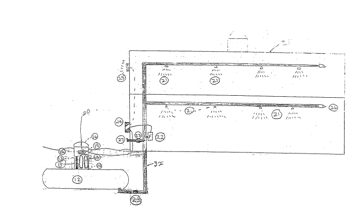
Fig. 1 illustrates the fire protection system in accordance with the invention.
DETAILED DESCRIPTION OF THE INVENTION
Fig. 1 illustrates the fire protection system in accordance with the invention. Water
storage vessel 12 is buried beneath the ground next to structure 30 which is the building
to be protected. The positioning and distance is not critical1 howeverj it should be as
close as practical to reduce the amount of piping required, and to keep frictional pipe
losses minimal. Water storage vessel 12 should be of the type certified by the American
Society of Manufacturing Engineers and Underwriter's Laboratory for direct burial and
capable of withstanding a test pressure of 1000 psi and a working pressure of 150 psi.
Preferably vessel 12 is constructed of 1/4 inch carbon steel having an exterior epoxy
coating. It is also preferable to have sacrificial anodes on the tank and thsreby achieve
a useful life of 20+ years. The size of vessel 12 is dependent upon the size of the
,~
:
structure to be protected and evacuation and fire department response times, however,
a five hundred gallon tank ~should be sufficient for most situations.
The tank is filled via 2 inch Filler pipe 13. Riser 32 connects vessel 12 to piping
connecting thermally activated sprinkler heads 21. The diameter of riser 32 as well as
other pipe sizes, and the number and placement of sprinkler heads 21 vary according to
certified hydraulic designers plans for the structure to be protected. Sprinkler heads 21
are preferably the quick response type with frangible glass triggers, brass or chrome
finish, capable of responding at temperatures between 135 and 155 degrees Fahrenheit.
Manway 17 is attached to vessel 12, preferably 48 inches tall and approximately
24 inches in diameter. The 48 inch length should be sufficient to bury vessel 12 deep
enough to prevent water stored from freezing in all but the most severe climates. 1n
5 locations that experience extreme cold temperatures, the length of manway 17 would be
extended to ensure that vessel 12 is protected from freezing. Also, a thermal blanket
. cover could be placed on the tank.
Manway 17 is protected against unauthorized access by locking cover 16.
Housed within manway 17 is one or rnore bottles 18 cont~ining a non-combustible
10 gas. Preferably, nitrogen would be used, however, carbon dioxide, or any other gas that
would not support combustion could be substituted. A single 125 cubic foot bottle of
nitrogen is sufficien~ to pump approximately 250 gallons of water according to the
following calculation:
((System Design Pressure P + 14.7 PSIA ~1 atm}) . 14.7 {1 atm}) x ~Vessel
5 Capacity . 7.48~
Bottle(s) 18 is(are) connected to regulator 20 via manifold 19. Regulator 20 is
preferably a two stage regulator with a 0 -2500 psi source and 0 -125 psi delivery ratings.
A two stage regulator provides a more steady pressure than a single stage unit.
Regulator 20 is preferably adapted with a tamper proof adjustment so that the selected
20 setting cannot be changed once set except by the owner of the system. The nitrogen
gas is delivered from regulator 20 via connections 14 which are preferably 1/2 inch
stainless steel flexi-hose and corresponding fittings.
-~ 2~7~3~
The system is equipped with pressure switch 15 which senses any variation of
pressure within ~he system and activates alarrn 25 via annunciator panel 24. Annunciator
panel 24 preferably has two zones to indicate the type of alarm; 24 volt battery back-up
in case of power failures. It is also preferably that the alarm system be equipped with all
`~ 5 weather, tamper proof, rate of rise-type heat detectors. Pull stations at convenient
locations such as main entrances would also be part of the total system. A horn capable
of emitting a warning of at least 92 decibels in volume plus a strobe light of at least 8000
candlepower would provide a warning to those in the vicinity. It is also preferable to have
annunciator pane 24 equipped with an auto alarm dialer capable of calling the local fire
department to report the fire.
Additionally, at the base of riser 32 is water flow detector 22 which is wired to
annunciator panel 24 on a separate zone. Once water is flowing in the system as a result
of one or more sprinkler heads being activated, or as a result of a leak, the owner or the
local fire department would be alerted.
Switch 15 and detector 22 are made tamper proof to prevent unau~horized
disablement.
A single inlet brass standpipe connection 27 is provided on the face of the
structure 3~ to which the fire department would be able to attach a hose and, thus,
continue to deliver water to a fire via sprinkler heads 21.
2 o Water check valve 23 is provided in riser 32 below the frost line which restricts the
flow of water until one or more of sprinkler heads 21 are activated by the heat of the fire.
Valve 23 is held closed by either air pressure or anti-freeze protected water. Another
.
3 ~ 7
check valve 23 is provided for standpipe connection 27. The system is back pressured
to hold closed valves 23 by introducing air or an~-freeze protected wa~er via one or more
fittings 26.
While there have been described what are at present considered to be the
5 preferred embodiments of this invention, it will be obvious to those skilled in the art that
various changes and modifications rnay be made therein without departin~ from the
invention and it is, therefore, aimed to cover all such changes and modifications as fall
within the true spirit and scope of the invention.