Language selection

Search

Patent 2075437 Summary

Third-party information liability

Some of the information on this Web page has been provided by external sources. The Government of Canada is not responsible for the accuracy, reliability or currency of the information supplied by external sources. Users wishing to rely upon this information should consult directly with the source of the information. Content provided by external sources is not subject to official languages, privacy and accessibility requirements.

Claims and Abstract availability

Any discrepancies in the text and image of the Claims and Abstract are due to differing posting times. Text of the Claims and Abstract are posted:

  • At the time the application is open to public inspection;
  • At the time of issue of the patent (grant).
(12) Patent Application: (11) CA 2075437
(54) English Title: CONTAINER WITH CURLED TAMPER-EVIDENT BAND TO RETAIN CLOSURE
(54) French Title: CONTENANT MUNI D'UNE BANDE INCURVEE INVIOLABLE SERVANT A LA FIXATION DU FERMOIR
Status: Deemed Abandoned and Beyond the Period of Reinstatement - Pending Response to Notice of Disregarded Communication
Bibliographic Data
(51) International Patent Classification (IPC):
  • B65D 55/06 (2006.01)
  • B65D 43/02 (2006.01)
(72) Inventors :
  • LUCH, DANIEL (United States of America)
  • CHENAULT, RAWSON (United States of America)
(73) Owners :
  • CAP SNAP CO.
(71) Applicants :
  • CAP SNAP CO. (United States of America)
(74) Agent: SMART & BIGGAR LP
(74) Associate agent:
(45) Issued:
(22) Filed Date: 1992-08-06
(41) Open to Public Inspection: 1993-02-08
Availability of licence: N/A
Dedicated to the Public: N/A
(25) Language of filing: English

Patent Cooperation Treaty (PCT): No

(30) Application Priority Data:
Application No. Country/Territory Date
07/741,650 (United States of America) 1991-08-07

Abstracts

English Abstract


ABSTRACT OF THE DISCLOSURE
A thin-walled, wide mouth molded plastic container is
provided with a tamper evident band initially molded as a
straight-walled cylinder spaced outwardly of the lip of the
container and connected thereto by a frangible horizontal
bridge. The upper edge of the cylindrical band extends above
the level of the container lip. Subsequent to molding and
preferably before capping, the band is curled inward by
application of a curling tool. The container lid is axially
applied, the outer edge of the lid displacing the curled band
outward. The resilience of the band and bridge permits outward
deflection and immediate restoration of the curl to its initial
position. The curl prevents removal of the lid without
fracture of the bridge and removal of the tamper-evident band.


Claims

Note: Claims are shown in the official language in which they were submitted.

-6-
WHAT IS CLAIMED IS:
1. A thin-walled, molded, resilient plastic container
comprising a wall having an upper lip having an uppermost edge,
an initially cylindrical tamper-evident band spaced outwardly
and extending above the top surface of said lip formed of a
curlable material, and frangible means joining said band to
said wall adjacent said lip, said band being deformed, the
upper portion of said band curling downward-inward in a curled
portion, said curled portion having a lowermost edge opposed
to and spaced above said uppermost edge.
2. A container according to claim 1 in which said
lip has a downward-outward curved extension, said frangible
means connecting the lower edge of said extension to the lower
edge of said band.
3. In combination, a container according to claim 1
and a lid, said lid having a top closing off the upper end
of said container, said disk having an outer edge and an
outward extending portion extending outward beyond said outer,
edge interposed between said lowermost edge and said uppermost
edge, whereby said lid cannot be removed without fracturing
said frangible means and removing said tamper-evident band.
4. The combination of claim 3 in which said lid
further comprises seal means sealingly engaging said lip.
5. The combination of claim 4 in which the outer edge
of said disk engages the interior of said wall of said
container and which further comprises an upward extending
vertical edge, a ring extending outward from said vertical
edge and engaging the top of said lip, and in which said
terminus is located immediately above said ring.
6. The combination of claim 5 which further comprises
a downward extending skirt on the outer edge of said ring,
said skirt engaging the exterior of said lip.
7. A method of forming a tamper-evident closure of
a container with a lid comprising
providing a molded plastic container formed of a
curlable material having a wall formed with an upper lip having
an uppermost edge, an initially cylindrical tamper-evident

-7-
band spaced outwardly and extending above the level of said
lip and frangible means joining said band to said wall adjacent
said lip,
axially applying a curling tool to the upper end of
said band to form an inward-downward curl in excess of 900
to said band having a lowermost edge opposed to and spaced
above said uppermost edge,
providing a lid having an outside diameter greater than
said lip and less than the initial width of said band,
forcing said lid axially downward toward said container,
said outside diameter resiliently displacing said curl outward
to permit said lid to engage said lip, allowing said curl to
return to initial position with said lowermost edge spaced
above said lid, whereby said lid cannot be removed without
fracturing said frangible means and removing said tamper-
evident band.
8. The method of claim 7 in which said container and
lid having cooperative seal means which interengage when said
lid is forced onto said lip.
9. In combination, a container according to Claim
1 and a lid, said lid comprising a top closing off the upper
end of said container and extending outward beyond said lip
and interposed between said lip and said lowermost edge of
the inward curled portion of said band, a first portion
engaging the inside of the upper portion of said wall below
said lip and a peripheral depending skirt engaging the outside
of said lip disposed inward of said band, whereby said lid
cannot be removed without fracturing said frangible means and
removing said band.

Description

Note: Descriptions are shown in the official language in which they were submitted.


2~7~437
CONTAIMER WITH CURLED TAMPER-EVIDENT
BAND TO RETAIN CLOSURE
BACKGROUND OF THE INVENTION
1. Field of the Invention
This invention reIates to a new and improved container
with a tamper-evident band to retain a closure. More
5 particularly, the invention relates to a~thin-walled, wide
mouth container having a band attached to its upper peripheral
edge which is inwardly curled to retain a cover lid. To remove
the lid, the band must be removed, and this makes the container
tamper-evident.
2. Description of Related Art
Curling of plastic cylindrical bands is known in the
art. For example, applying a concave tool to the edge of a
cylindrical plastic member is shown in numerous patents to
~: Thompson, U. S. Patents Nos. 4,708,255, 4,709,824; 4,793,506;
4,872,304; 4,823,967; 4,811,857; and 4,856,667 being typical.
These patents disclose a curled bead which is resilient and
is compressed when a screw closure is applied to a container
neck. Similar curling techniques are employed in the present
invention, but the curled flange is employed for a totally
different purpose, namely, the band curls over the edge of
a lid and holds the lid in place until the band is removed.
SIJMMARY OF THE INVENTI'~N
The container of the present invention is initially
molded with a straight-walled cylindrical band spaced outwardly
of, but connected to, the outside of the container body through
a frangible line of weakness. Subsequent to molding, a curling
tool engages the edge of the band and the tool is formed with

2~ 137
--2--
a concavity which causes the edge of the band to curl inwardly
and downwardly. A lid is applied axially to the container.
As the lid engages the curled band, it resiliently forces the
band outwardly until the curled portion thereof snaps over
the top of the lid. So long as the band is intact, the lid
cannot be removed. However, the band may be broken from the
container along the line of weakness and thereafter the lid
may be removed. Fracture at the line of weakness gives
evidence of tampering.
Alternatively, the curling of the tamper-evident band
may be performed after the lid is in place.
BRIEF DESCRIPTION OF THE DRAWINGS
The accompanying drawings, which are incorporated in
and form a part of this specification, illustrate embodiments
of the invention and, together with the description, serve
to explain the principles of the invention:
Fig. 1 is a top plan view of a container formed in
accordance with the present invention before curling of the
tamper-evident band.
Fig. 2 is a sectional view taken substantially along
the line 2--2 of Fig. 1.
Fig. 3 is a schematic exploded sectional view showing
the curling tools immediately before engaging the tamper-
evident band.
Fig. 4 is a view similar to Fig. 2 showing the curl
formed in the upper edge of the band.
Fig. 5 is a sectional view showing application of the
lid.
DETAILED DESCRIPTION OF THE PREFERRED EMBODIMENT
Reference will now be made in detail to the preferred
embodiments of the invention, examples of which are illustrated
in the accompanying drawings. While the invention will be
described in conjunction with the preferred embodiments, it
will be understood that they are not intended to limit the
invention to those embodiments. Onthe contrary, the invention
is intended to cover alternatives, modifications and

2~75437
--3--
equivalents, which may be included within the spirit and scope
of the invention as defined by the appended claims.
Container 11 is subject to wide modification. As here
shown, it is depicted as a thin-walled, wide mouth container
preferably made of high density polyethylene or polypropylene
of the type used for various dairy products such as margarine,
cottage cheese, and the like. It will be understood that the
details of the structure of the container 11 are subject to
wide modification. As illustrated herein, the container ll
has anupwardly-outwardly inclined conical wall 12 and a bottom
13. At the top edge of the wall 12 is an outwardly curled
lip 14 which merges in a vertically downwardly extending
portion 16. Extending outward from the lower edge of portion
16 are thin, substantially horizontal frangible bridges 17
which constitutes a line (or more precisely, a circle) of
weakness. Bridges 17 are preferably interrupted --- i.e.,
made of angularly spaced connections separated by gaps.
Extending upward from the bridge 17 is a tamper-evident band
18 which is initially cylindrical as shown in Fig. 2.
The container shown in Fig. 2 is modified by the tooling
shown in Fig. 3. Above the upper eclge of band 18 is a ring-
shaped tool 21 having a concavity 22 formed on its lower
surface. Below the band 18 is a second re-shaped tool 24 which
supports the bottom edge of the band 18 and the bridge 17.
Tool 21 is brought vertically downwardly and as the upper edge
of band 18 engages the concavity 22 it is bent into an inward
curl 26 shown in Fig. 4, the curl 26 having a terminus 27
spaced upward from lip 14.
A lid 31 which may be used with the container 11 is
shown in Fig. 5. Such a lid 31 may have a top disc 32 having
a diameter less than that of the top of wall 12. The outer
edge of disc 32 is formed with an upward-extending edge 33
and extending outward from edge 33 is an annular ring 34 which
extends over the lip 14. A downward directed skirt 36 is
connected to the outer edge of ring 34.
Lid 31 may be applied to th~ container 11 in the
condition shown in Fig. 4 by moving the lid 31 vertically

2~7~437
downwardly. The bottom edge of skirt 36 engages the curl 26
and bends it outwardly sufficiently so that the lid may pass
beyond the curl 26 and seat on the container 11 as shown in
Fig. 5. Because of the resilient nature of the bridges 17
and the band 18, the curl 26 returns to the position shown
in Fig. 4. As shown in Fig. 5, the curl 26 thus encases the
ring 34 of lid 31, holding the same in position. The container
is sealed by circles of contact 38 between the upward extending
edge 33 and the inside of the wall 12 and by the circle of
contact 39 between the underside of the ring 34 and the top
o~ lip 14.
The lid 31 may not be removed so long as the curl 26
engages the ring 34. If one attempts to remove the lid,
bridges 17 breaks, giving evidence of tampering. When the
consumer wishes to open the container, band 18 is broken away
by fracturing bridges 17. By prying upward on the bottom edge
of skixt 36, the user may remove the lid 31. Lid 31 is
reclosable since it is merely necessary to force it onto the
lip 14 if desired.
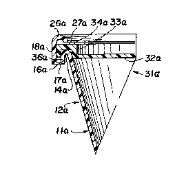
In the modification of Figs. 6 and 7, lid 31a is applied
to the container lla before the band 18a is curled. After
application of lid 31a, tools 21a and 24a perform the curling
op~ration.
In other respects the modification of Figs. 6 and 7
resembles that of the preceding modification and the same
reference numerals followed by the subscript a indicated
corresponding elements.
In the foregoing description and following claims the
terms "circle", "ring" or "cylinder" have been used. It will
be understood,however, that the container may be oval,
rectangular or other non-circular shapes. The terms will be
understood in accordance with this paragraph.
The foregoing descriptions of specific embodiments of
the present invention have been presented for purposes of
illustration and description. They are not intended to be
exhaustive or to limit the invention to the precise forms
disclosed, and obviously many modifications and variations

2 ~ 3 7
-5-
are possible in light of the above teaching. The embodiments
were chosen and described in order to best explain the
principles of the invention and its practical application,
to thereby enable others skilled in the art to best utilize
the invention and various embodiments with various
modifications as are suited to the particular use contemplated.
It is intended that the scope of the invention be defined by
the Claims appended hereto and their equivalents.

Representative Drawing
A single figure which represents the drawing illustrating the invention.
Administrative Status

2024-08-01:As part of the Next Generation Patents (NGP) transition, the Canadian Patents Database (CPD) now contains a more detailed Event History, which replicates the Event Log of our new back-office solution.

Please note that "Inactive:" events refers to events no longer in use in our new back-office solution.

For a clearer understanding of the status of the application/patent presented on this page, the site Disclaimer , as well as the definitions for Patent , Event History , Maintenance Fee  and Payment History  should be consulted.

Event History

Description Date
Inactive: IPC from MCD 2006-03-11
Time Limit for Reversal Expired 1999-08-06
Application Not Reinstated by Deadline 1999-08-06
Deemed Abandoned - Failure to Respond to Maintenance Fee Notice 1998-08-06
Application Published (Open to Public Inspection) 1993-02-08

Abandonment History

Abandonment Date Reason Reinstatement Date
1998-08-06

Maintenance Fee

The last payment was received on 1997-07-18

Note : If the full payment has not been received on or before the date indicated, a further fee may be required which may be one of the following

  • the reinstatement fee;
  • the late payment fee; or
  • additional fee to reverse deemed expiry.

Patent fees are adjusted on the 1st of January every year. The amounts above are the current amounts if received by December 31 of the current year.
Please refer to the CIPO Patent Fees web page to see all current fee amounts.

Fee History

Fee Type Anniversary Year Due Date Paid Date
MF (application, 5th anniv.) - standard 05 1997-08-06 1997-07-18
Owners on Record

Note: Records showing the ownership history in alphabetical order.

Current Owners on Record
CAP SNAP CO.
Past Owners on Record
DANIEL LUCH
RAWSON CHENAULT
Past Owners that do not appear in the "Owners on Record" listing will appear in other documentation within the application.
Documents

To view selected files, please enter reCAPTCHA code :


To view images, click a link in the Document Description column. To download the documents, select one or more checkboxes in the first column and then click the "Download Selected in PDF format (Zip Archive)" or the "Download Selected as Single PDF" button.

List of published and non-published patent-specific documents on the CPD .

If you have any difficulty accessing content, you can call the Client Service Centre at 1-866-997-1936 or send them an e-mail at CIPO Client Service Centre.


Document
Description 
Date
(yyyy-mm-dd) 
Number of pages   Size of Image (KB) 
Abstract 1993-02-07 1 21
Claims 1993-02-07 2 88
Drawings 1993-02-07 2 48
Descriptions 1993-02-07 5 197
Representative drawing 1999-03-11 1 8
Courtesy - Abandonment Letter (Maintenance Fee) 1998-09-02 1 189
Reminder - Request for Examination 1999-04-06 1 117
Fees 1996-07-18 1 82
Fees 1995-07-25 1 76
Fees 1994-09-29 2 59
Prosecution correspondence 1992-10-18 1 40