Sélection de la langue

Search

Sommaire du brevet 2075437 

Énoncé de désistement de responsabilité concernant l'information provenant de tiers

Une partie des informations de ce site Web a été fournie par des sources externes. Le gouvernement du Canada n'assume aucune responsabilité concernant la précision, l'actualité ou la fiabilité des informations fournies par les sources externes. Les utilisateurs qui désirent employer cette information devraient consulter directement la source des informations. Le contenu fourni par les sources externes n'est pas assujetti aux exigences sur les langues officielles, la protection des renseignements personnels et l'accessibilité.

Disponibilité de l'Abrégé et des Revendications

L'apparition de différences dans le texte et l'image des Revendications et de l'Abrégé dépend du moment auquel le document est publié. Les textes des Revendications et de l'Abrégé sont affichés :

  • lorsque la demande peut être examinée par le public;
  • lorsque le brevet est émis (délivrance).
(12) Demande de brevet: (11) CA 2075437
(54) Titre français: CONTENANT MUNI D'UNE BANDE INCURVEE INVIOLABLE SERVANT A LA FIXATION DU FERMOIR
(54) Titre anglais: CONTAINER WITH CURLED TAMPER-EVIDENT BAND TO RETAIN CLOSURE
Statut: Réputée abandonnée et au-delà du délai pour le rétablissement - en attente de la réponse à l’avis de communication rejetée
Données bibliographiques
(51) Classification internationale des brevets (CIB):
  • B65D 55/06 (2006.01)
  • B65D 43/02 (2006.01)
(72) Inventeurs :
  • LUCH, DANIEL (Etats-Unis d'Amérique)
  • CHENAULT, RAWSON (Etats-Unis d'Amérique)
(73) Titulaires :
  • CAP SNAP CO.
(71) Demandeurs :
  • CAP SNAP CO. (Etats-Unis d'Amérique)
(74) Agent: SMART & BIGGAR LP
(74) Co-agent:
(45) Délivré:
(22) Date de dépôt: 1992-08-06
(41) Mise à la disponibilité du public: 1993-02-08
Licence disponible: S.O.
Cédé au domaine public: S.O.
(25) Langue des documents déposés: Anglais

Traité de coopération en matière de brevets (PCT): Non

(30) Données de priorité de la demande:
Numéro de la demande Pays / territoire Date
07/741,650 (Etats-Unis d'Amérique) 1991-08-07

Abrégés

Abrégé anglais


ABSTRACT OF THE DISCLOSURE
A thin-walled, wide mouth molded plastic container is
provided with a tamper evident band initially molded as a
straight-walled cylinder spaced outwardly of the lip of the
container and connected thereto by a frangible horizontal
bridge. The upper edge of the cylindrical band extends above
the level of the container lip. Subsequent to molding and
preferably before capping, the band is curled inward by
application of a curling tool. The container lid is axially
applied, the outer edge of the lid displacing the curled band
outward. The resilience of the band and bridge permits outward
deflection and immediate restoration of the curl to its initial
position. The curl prevents removal of the lid without
fracture of the bridge and removal of the tamper-evident band.

Revendications

Note : Les revendications sont présentées dans la langue officielle dans laquelle elles ont été soumises.


-6-
WHAT IS CLAIMED IS:
1. A thin-walled, molded, resilient plastic container
comprising a wall having an upper lip having an uppermost edge,
an initially cylindrical tamper-evident band spaced outwardly
and extending above the top surface of said lip formed of a
curlable material, and frangible means joining said band to
said wall adjacent said lip, said band being deformed, the
upper portion of said band curling downward-inward in a curled
portion, said curled portion having a lowermost edge opposed
to and spaced above said uppermost edge.
2. A container according to claim 1 in which said
lip has a downward-outward curved extension, said frangible
means connecting the lower edge of said extension to the lower
edge of said band.
3. In combination, a container according to claim 1
and a lid, said lid having a top closing off the upper end
of said container, said disk having an outer edge and an
outward extending portion extending outward beyond said outer,
edge interposed between said lowermost edge and said uppermost
edge, whereby said lid cannot be removed without fracturing
said frangible means and removing said tamper-evident band.
4. The combination of claim 3 in which said lid
further comprises seal means sealingly engaging said lip.
5. The combination of claim 4 in which the outer edge
of said disk engages the interior of said wall of said
container and which further comprises an upward extending
vertical edge, a ring extending outward from said vertical
edge and engaging the top of said lip, and in which said
terminus is located immediately above said ring.
6. The combination of claim 5 which further comprises
a downward extending skirt on the outer edge of said ring,
said skirt engaging the exterior of said lip.
7. A method of forming a tamper-evident closure of
a container with a lid comprising
providing a molded plastic container formed of a
curlable material having a wall formed with an upper lip having
an uppermost edge, an initially cylindrical tamper-evident

-7-
band spaced outwardly and extending above the level of said
lip and frangible means joining said band to said wall adjacent
said lip,
axially applying a curling tool to the upper end of
said band to form an inward-downward curl in excess of 900
to said band having a lowermost edge opposed to and spaced
above said uppermost edge,
providing a lid having an outside diameter greater than
said lip and less than the initial width of said band,
forcing said lid axially downward toward said container,
said outside diameter resiliently displacing said curl outward
to permit said lid to engage said lip, allowing said curl to
return to initial position with said lowermost edge spaced
above said lid, whereby said lid cannot be removed without
fracturing said frangible means and removing said tamper-
evident band.
8. The method of claim 7 in which said container and
lid having cooperative seal means which interengage when said
lid is forced onto said lip.
9. In combination, a container according to Claim
1 and a lid, said lid comprising a top closing off the upper
end of said container and extending outward beyond said lip
and interposed between said lip and said lowermost edge of
the inward curled portion of said band, a first portion
engaging the inside of the upper portion of said wall below
said lip and a peripheral depending skirt engaging the outside
of said lip disposed inward of said band, whereby said lid
cannot be removed without fracturing said frangible means and
removing said band.

Description

Note : Les descriptions sont présentées dans la langue officielle dans laquelle elles ont été soumises.

2~7~437
CONTAIMER WITH CURLED TAMPER-EVIDENT
BAND TO RETAIN CLOSURE
BACKGROUND OF THE INVENTION
1. Field of the Invention
This invention reIates to a new and improved container
with a tamper-evident band to retain a closure. More
5 particularly, the invention relates to a~thin-walled, wide
mouth container having a band attached to its upper peripheral
edge which is inwardly curled to retain a cover lid. To remove
the lid, the band must be removed, and this makes the container
tamper-evident.
2. Description of Related Art
Curling of plastic cylindrical bands is known in the
art. For example, applying a concave tool to the edge of a
cylindrical plastic member is shown in numerous patents to
~: Thompson, U. S. Patents Nos. 4,708,255, 4,709,824; 4,793,506;
4,872,304; 4,823,967; 4,811,857; and 4,856,667 being typical.
These patents disclose a curled bead which is resilient and
is compressed when a screw closure is applied to a container
neck. Similar curling techniques are employed in the present
invention, but the curled flange is employed for a totally
different purpose, namely, the band curls over the edge of
a lid and holds the lid in place until the band is removed.
SIJMMARY OF THE INVENTI'~N
The container of the present invention is initially
molded with a straight-walled cylindrical band spaced outwardly
of, but connected to, the outside of the container body through
a frangible line of weakness. Subsequent to molding, a curling
tool engages the edge of the band and the tool is formed with

2~ 137
--2--
a concavity which causes the edge of the band to curl inwardly
and downwardly. A lid is applied axially to the container.
As the lid engages the curled band, it resiliently forces the
band outwardly until the curled portion thereof snaps over
the top of the lid. So long as the band is intact, the lid
cannot be removed. However, the band may be broken from the
container along the line of weakness and thereafter the lid
may be removed. Fracture at the line of weakness gives
evidence of tampering.
Alternatively, the curling of the tamper-evident band
may be performed after the lid is in place.
BRIEF DESCRIPTION OF THE DRAWINGS
The accompanying drawings, which are incorporated in
and form a part of this specification, illustrate embodiments
of the invention and, together with the description, serve
to explain the principles of the invention:
Fig. 1 is a top plan view of a container formed in
accordance with the present invention before curling of the
tamper-evident band.
Fig. 2 is a sectional view taken substantially along
the line 2--2 of Fig. 1.
Fig. 3 is a schematic exploded sectional view showing
the curling tools immediately before engaging the tamper-
evident band.
Fig. 4 is a view similar to Fig. 2 showing the curl
formed in the upper edge of the band.
Fig. 5 is a sectional view showing application of the
lid.
DETAILED DESCRIPTION OF THE PREFERRED EMBODIMENT
Reference will now be made in detail to the preferred
embodiments of the invention, examples of which are illustrated
in the accompanying drawings. While the invention will be
described in conjunction with the preferred embodiments, it
will be understood that they are not intended to limit the
invention to those embodiments. Onthe contrary, the invention
is intended to cover alternatives, modifications and

2~75437
--3--
equivalents, which may be included within the spirit and scope
of the invention as defined by the appended claims.
Container 11 is subject to wide modification. As here
shown, it is depicted as a thin-walled, wide mouth container
preferably made of high density polyethylene or polypropylene
of the type used for various dairy products such as margarine,
cottage cheese, and the like. It will be understood that the
details of the structure of the container 11 are subject to
wide modification. As illustrated herein, the container ll
has anupwardly-outwardly inclined conical wall 12 and a bottom
13. At the top edge of the wall 12 is an outwardly curled
lip 14 which merges in a vertically downwardly extending
portion 16. Extending outward from the lower edge of portion
16 are thin, substantially horizontal frangible bridges 17
which constitutes a line (or more precisely, a circle) of
weakness. Bridges 17 are preferably interrupted --- i.e.,
made of angularly spaced connections separated by gaps.
Extending upward from the bridge 17 is a tamper-evident band
18 which is initially cylindrical as shown in Fig. 2.
The container shown in Fig. 2 is modified by the tooling
shown in Fig. 3. Above the upper eclge of band 18 is a ring-
shaped tool 21 having a concavity 22 formed on its lower
surface. Below the band 18 is a second re-shaped tool 24 which
supports the bottom edge of the band 18 and the bridge 17.
Tool 21 is brought vertically downwardly and as the upper edge
of band 18 engages the concavity 22 it is bent into an inward
curl 26 shown in Fig. 4, the curl 26 having a terminus 27
spaced upward from lip 14.
A lid 31 which may be used with the container 11 is
shown in Fig. 5. Such a lid 31 may have a top disc 32 having
a diameter less than that of the top of wall 12. The outer
edge of disc 32 is formed with an upward-extending edge 33
and extending outward from edge 33 is an annular ring 34 which
extends over the lip 14. A downward directed skirt 36 is
connected to the outer edge of ring 34.
Lid 31 may be applied to th~ container 11 in the
condition shown in Fig. 4 by moving the lid 31 vertically

2~7~437
downwardly. The bottom edge of skirt 36 engages the curl 26
and bends it outwardly sufficiently so that the lid may pass
beyond the curl 26 and seat on the container 11 as shown in
Fig. 5. Because of the resilient nature of the bridges 17
and the band 18, the curl 26 returns to the position shown
in Fig. 4. As shown in Fig. 5, the curl 26 thus encases the
ring 34 of lid 31, holding the same in position. The container
is sealed by circles of contact 38 between the upward extending
edge 33 and the inside of the wall 12 and by the circle of
contact 39 between the underside of the ring 34 and the top
o~ lip 14.
The lid 31 may not be removed so long as the curl 26
engages the ring 34. If one attempts to remove the lid,
bridges 17 breaks, giving evidence of tampering. When the
consumer wishes to open the container, band 18 is broken away
by fracturing bridges 17. By prying upward on the bottom edge
of skixt 36, the user may remove the lid 31. Lid 31 is
reclosable since it is merely necessary to force it onto the
lip 14 if desired.
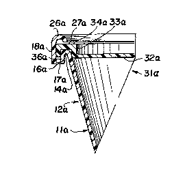
In the modification of Figs. 6 and 7, lid 31a is applied
to the container lla before the band 18a is curled. After
application of lid 31a, tools 21a and 24a perform the curling
op~ration.
In other respects the modification of Figs. 6 and 7
resembles that of the preceding modification and the same
reference numerals followed by the subscript a indicated
corresponding elements.
In the foregoing description and following claims the
terms "circle", "ring" or "cylinder" have been used. It will
be understood,however, that the container may be oval,
rectangular or other non-circular shapes. The terms will be
understood in accordance with this paragraph.
The foregoing descriptions of specific embodiments of
the present invention have been presented for purposes of
illustration and description. They are not intended to be
exhaustive or to limit the invention to the precise forms
disclosed, and obviously many modifications and variations

2 ~ 3 7
-5-
are possible in light of the above teaching. The embodiments
were chosen and described in order to best explain the
principles of the invention and its practical application,
to thereby enable others skilled in the art to best utilize
the invention and various embodiments with various
modifications as are suited to the particular use contemplated.
It is intended that the scope of the invention be defined by
the Claims appended hereto and their equivalents.

Dessin représentatif
Une figure unique qui représente un dessin illustrant l'invention.
États administratifs

2024-08-01 : Dans le cadre de la transition vers les Brevets de nouvelle génération (BNG), la base de données sur les brevets canadiens (BDBC) contient désormais un Historique d'événement plus détaillé, qui reproduit le Journal des événements de notre nouvelle solution interne.

Veuillez noter que les événements débutant par « Inactive : » se réfèrent à des événements qui ne sont plus utilisés dans notre nouvelle solution interne.

Pour une meilleure compréhension de l'état de la demande ou brevet qui figure sur cette page, la rubrique Mise en garde , et les descriptions de Brevet , Historique d'événement , Taxes périodiques et Historique des paiements devraient être consultées.

Historique d'événement

Description Date
Inactive : CIB de MCD 2006-03-11
Le délai pour l'annulation est expiré 1999-08-06
Demande non rétablie avant l'échéance 1999-08-06
Réputée abandonnée - omission de répondre à un avis sur les taxes pour le maintien en état 1998-08-06
Demande publiée (accessible au public) 1993-02-08

Historique d'abandonnement

Date d'abandonnement Raison Date de rétablissement
1998-08-06

Taxes périodiques

Le dernier paiement a été reçu le 1997-07-18

Avis : Si le paiement en totalité n'a pas été reçu au plus tard à la date indiquée, une taxe supplémentaire peut être imposée, soit une des taxes suivantes :

  • taxe de rétablissement ;
  • taxe pour paiement en souffrance ; ou
  • taxe additionnelle pour le renversement d'une péremption réputée.

Les taxes sur les brevets sont ajustées au 1er janvier de chaque année. Les montants ci-dessus sont les montants actuels s'ils sont reçus au plus tard le 31 décembre de l'année en cours.
Veuillez vous référer à la page web des taxes sur les brevets de l'OPIC pour voir tous les montants actuels des taxes.

Historique des taxes

Type de taxes Anniversaire Échéance Date payée
TM (demande, 5e anniv.) - générale 05 1997-08-06 1997-07-18
Titulaires au dossier

Les titulaires actuels et antérieures au dossier sont affichés en ordre alphabétique.

Titulaires actuels au dossier
CAP SNAP CO.
Titulaires antérieures au dossier
DANIEL LUCH
RAWSON CHENAULT
Les propriétaires antérieurs qui ne figurent pas dans la liste des « Propriétaires au dossier » apparaîtront dans d'autres documents au dossier.
Documents

Pour visionner les fichiers sélectionnés, entrer le code reCAPTCHA :


Pour visualiser une image, cliquer sur un lien dans la colonne description du document. Pour télécharger l'image (les images), cliquer l'une ou plusieurs cases à cocher dans la première colonne et ensuite cliquer sur le bouton "Télécharger sélection en format PDF (archive Zip)" ou le bouton "Télécharger sélection (en un fichier PDF fusionné)".

Liste des documents de brevet publiés et non publiés sur la BDBC .

Si vous avez des difficultés à accéder au contenu, veuillez communiquer avec le Centre de services à la clientèle au 1-866-997-1936, ou envoyer un courriel au Centre de service à la clientèle de l'OPIC.


Description du
Document 
Date
(aaaa-mm-jj) 
Nombre de pages   Taille de l'image (Ko) 
Abrégé 1993-02-07 1 21
Revendications 1993-02-07 2 88
Dessins 1993-02-07 2 48
Description 1993-02-07 5 197
Dessin représentatif 1999-03-11 1 8
Courtoisie - Lettre d'abandon (taxe de maintien en état) 1998-09-02 1 189
Rappel - requête d'examen 1999-04-06 1 117
Taxes 1996-07-18 1 82
Taxes 1995-07-25 1 76
Taxes 1994-09-29 2 59
Correspondance de la poursuite 1992-10-18 1 40