Note: Descriptions are shown in the official language in which they were submitted.
5~".~9
CUTI~[NG TOOL FOR ~llLLING MAC~ S
BACRGROUND OF THE ~VENTION
1. Fiel~ of the invention:
The present mvention relates to cutting tooLs used on milling
machine~ for machiILing a workpiece, and particularly to a cutting
tool composed of a side cutter oriented transver ely to the
rotatianal ax~s of the mil~ing machine spdndle f or perf orming
contour machining operations in three dimensions.
2. De~ption of the Prior Art:
Milling machines are in widespread use for mach~ning metal
workp~eces into a fini3hed metal product. Machining operations of
this type range from simple strPlght cuts and bores to forming
complex three dimen~ional contours. Mil~ing machines are divided
into horizontal and vertical types depending on the orientation of
ff~e sEIindle axis. Cammon to a~l milling machines is a bed to which
is connected a workhoJder and at least one coaumn for supporting a
spLndle head. qhe spindle head contains the spindle and l~ve for
the ~p~ndle, and i8 movable in rela1:ion to the workh~Lder. The
workpiece is affixed to the workh~lder and a cutting tool i3
connected with the spindle. The cutting tool is rotated by the
spindle drive and is brought into contact with the workpiece by
movement of the spindle head.
~ n the case of machining contours in fflree dimension~,
typica~ly many passes are made by a cutting tool in a progressive
f ashion over the area being contoured. Figures 1 and lA show a
--1--
~ ~ 9
typical state of the art milling operation in which a spindle 20
turns an end mi~l cutter 22 which makes a series of groove cuts 24
to form a contour 26 on a workpiece 28. Due to the ccanplexity of
the movements of the cutter to achieve the de~ired contour, use of
Computer Numerical Control (CNC) syetems are now becoming the
standard to control movement of ~he cutting tool in relation to the
workpiece. ~ CNC, a programmer converts movements of the
cutting too~ into a digital sequence which is then fed into a
computer. The computer is linked electronically to the drives for
three dimensional movement of the spindle head and the spindle
drive. A computer program converts the 3;g;tal data into
electronic commands that regulate the feed and speed rates.
The m;ll;ng operation just described suffers fram a number of
drawbacks. The large number of passes of the end mi~l cutter
results in an extensive amount of time required to complete a
contouring operation on a workpiece. Further, the workpiece comes
into contact with only a portion of the cutting edge of the end
m;ll cutter as each groove cut is made. This is becau~e the end
m;ll is rotating about an axis which moves latera~ly with respect to
the workpiece. Accordingly, the cutting edge of the end mi~l does
not directly engage the workpiece in the direction of feed,
resulting in inefficient cutting. Still further, a second machining
operation is required to smooth-out the grooves cuts.
As further examples of miLling machines, the following U.S.
patents are of interest.
Patent 1,029,402 to Ritter, dated June 11, 1912, discloses a
--2--
~,~.9
mil~ing tool attachment for a rlrlll press. Bevel gears connected
~th the F~pindle drive a gear set that in turn drive~ a ~ide cutter
oriented perpendicular with respect to the axis of rotation of the
spindle. The resulting milling tooJ attachment ha~ only a vertical
axLs of movement, and i9 not suited for use in three dimensional
contour millingO
Patent 1,040,9~4 to Johnson, dated Octo}~er 8, 1912, discloses
an attachment for mil~ing machines which en~hle~ quick change of
cutters and supports various f orms and shape~ of cutters. The
attachment is composed of a U-shaped casing for supporting the
cutter and associated gearing which permits turning of the cutter
in a direction parallel with respect to the spindle of the machine.
Patent 2,963,944 to Strauss, dated December 13, 1960,
tRcloses a mill;ng machine which may be converted to various
orientations of the axis of rotation of the spindle. In ~is device,
the upper portion of the base carries a turret which carrieR the
spindle and its driYe. The turret is rotatable and a separately
powered vertical head i8 employed for vertical and angular m;lling.
Patent 4,993,138 to Yang, dat d February 19, 1991, discloses a
milling machine having a grooved overarm hori onta~ly disposed in
relation to the machine body. A vertical mi~ing attachment slides
along the grooved overarm for horizontal movement.
While the milling machine art is extremely well developed,
there yet remains the need for a mil~ing machine cutter to~ which
is structured and oriented 80 as to perf orm complex three
dimensional contour machining operations and which further provides
--3--
f or the cutting edges of the cutter to engage the work~iece in the
~ame ~;rection as the feed tl;rection~ thereby resulting in maximal
cutting ef ficiency.
Sl~MMARY OF TE1~3 INV~N~[ON
The pre~ent invention is a mil~ing machine cutter tool which is
structured and oriented 80 as to perf orm complex three dimen~ional
contour machining operations and which further provides for the
cutting edges of the cutter to engage the workpiece in the same
ection as the feed d;rection~ thereby resulting in maximal cutting
ef ficiency.
The cutting tool according to the present invention i8
composed, inter alia, of a sleeve that is rotatably mounted to the
milling machine, a qui~l axia~ly movable in the sleeve, a position
drive for selectively moving the qui~l rel~tive to the ~3leeve, a drive
shaft rotatably supported in the qui~l and connected at a forward
end thereof to a cutter drive, a cutter head connected to the
oppo~ite rear end of the qui~l, a worm gear set mounted in the
cutter head connecting gearably to the drive shaft, a cutter ~haft
mounted in the cutter head transversely in relation to the drive
shaft and gearably connected to the worm gear set, and a side
cutter connected to the cutter shaf t, the side cutter suppor~ng
teeth extending f orwardly of the cutting head.
~ one preferred embodiment, the tlrive shaft is pawered by a
self-con~ined cutter drive motor connected to the qui~L In a
second preferred enbodiment, the drive shaft ~s powered by the
' 9
sp~ndle drive system of the m;lling machine.
In operation, the ax~s of rotation of the side cutter is
adiusted 80 that the teeth of the side cutter engage the workpiece
in the f eed direction. A~ cuts are made in the workpiece, the
mill;ng machine moves the cutting tooJ vertically and horizontally
as reqn;red, while the qui~l is moved in and out with respect to the
~leeve as required to cause the teeth of the side cutter to engage
t~e workpiece and thereby provide the desired contour thereon.
Accordingly, it is an object of the present invention to
provide a m;ll;ng machine cutter tool which is structured and
oriented ~o as to perform complex three dimensional contour
machining operation~ and which further provide~ for the cutting
edges of the cutter to engage the workpiece in the same d; rection
a~ the feed direction, thereby resulting in maximal cut ;ng
ef ficiency.
These, and additional obiects, advantages, f eatures and
benefits of the present invention will become apparent frcan the
f oJlohing specification.
BRI~F DESCRIPq~ON OF TEIE DRAWINGS
Figure 1 is a partly f ragmentary side view of a conventional
m;ll;ng machine ~.ith an associated end mill cutter in the process of
providing a three dimensional contour on a worlcpiece by cutting a
series of groove cuts in the workpiece.
Figure lA is a detail view of the conventianal cutting process
as seen along lines lA-lA in E~gure 1.
2~ ,~9
Figure 2 is a perspective view of the cutting tool according
to the present invention mounted on a milling machine, shown in
operation cutting a three dimen~ional coaltour on a work~iece.
Figure 3 is a sirle view of the cutting tool according to the
present inventia~ seen along lines 3-3 in Figure 2, sho~nng possible
orientations of the cutting tooL
E~gure a, is a top plan view of the cutting tool accordinq to
the present invention seen along lines 4-4 in Figure 3.
Figure 5 is a side view of the cutting to~l according to the
present invention seen along lines 5-5 in Eigure 4.
Eiqure 6 is a side view of the cutting tool according to the
present invention seen along lines 6-6 in Figure 4.
Figure 7 is a f ragmentary sectional side view of the cutting
tool accor~ing to the present invention seen along ~ines 7-7 in
Figure 5.
Figure 8 is a sectional end view of the cut ;ng tool according
to the present invention seen along lines 8-8 in EYgure 7.
E~gure 9 i8 a f ragmentary ~ectional side view of the cutting
toal according to the present invention seen along ~ines 9-9 in
Eigure 6.
E~gure 10 is a f ragmentary side view of the cutting to~L
according to the present invention seen along lines 10-10 in E~gure
7.
Eigure 11 is a cross-sectional end view of the cutting to~
according to the present invention seen along lines 11-11 in EYgure
9.
--6--
Figure 12 is a partly sectional side view of the cutting tool
havirlg a precision ball screw positioning device.
Figure 13 is a partly sectional side view of the cutter
according to the present invention, shown in operation performing
three dimensional contour cutting of a workpiece.
D13TAIL13D D~SCRIeTION OF T~E PR~3FERR13D 13MBODIMENT
Ref erring now to the Drawing, Figure 2 shows the cutting tool
100 according to the present invention in operation mounted to a
milling machine 102 and cutting a complex three dimen~ional
contour 104 on a workpiece 106. The milling machine 102 mcludes
a base 102a, columns 102b, a ~pindle head holtler 102c vertically
movable along axis Y by a ~ve (not shown) with respect to the
columns, and a worl~older 102d horizontally movable along axis Z
by a drive (not shawn) with respect to the base. The cutting tool
100 i8 mounted to the spindle head holder 102c and is horizontally
movable with re~pect thereto along a~ X by a drive (not shown)
via a guideway 102e. Thus, the mi~ing machine 102 provides three
degrees of freedcm of movement of the cutting tool 100 relative to
the worl~?iece 106.
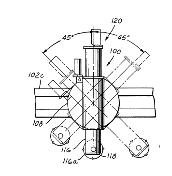
As exemplified by Figures 3 and 6, the cutting tool 100 is
mounted relative to the gui~eway 102e of the spindle head ho~ler
102c by means of a ircularly shaped swivel plate 108, a swivel
plate block 110 and swivel plate mounting bolt 112 which extends
through a slot 102e~ in the guideway 102e. Further, the cutt;ng
tool 100 has an a~lditional degree of freedom of movement in that
2~ , . 9
the cutting tool may rotate 90 degrees about the swivel plate
mounting bolt 112 ~45 degrees either side of the vertical Y axLs).
Rotation of the cutting tool is controJled by a ~ ve (not shc~wn).
Eigures 2 and 3 further ~how that the cutting tool 100
include~ a sleeve Ll4 connected with the swivel plate 108. The
sleeve receives a quill 116 which i~ axi~lly sl;~able within the
sleeve. At the forward end 116a of the qui~l 116 i8 located a si~le
cutter 118 f or perf orming a machining operation on the work~iece
106. At the rear end 116b of the quill is located a spindle drive
f or driving the ~ide cutter. The sp~ndle drive may be part of the
cutting tool, a6 shown by spindle drive 120, or may alternatively be
the spindle drive of the mi~ling machine.
Ref erring now to Eigures 4 through 12, the construction and
functioning of the cutting tool 100 will be detailed. In this regard,
E~gures 4 through 11 depict a pref erred embodiment of the
invention, while ~gure 12 depicts an improved va~;~tion thereof for
providing highest precision controJ of positional movement of the
l rel~tive to the sleeve.
Referring first~y to the en~odiment of the cutter tooJ 10
depicted in Eigures 4 through 12, the sleeve 114 i~ connected to
the swivel plate 108 via b~ts 122. The quill 116 is s~idably
received within the sleeve; lubrication therebetween i8 provided by
c~il introduced under air pressure in a manner well known in the
art. A locator ring 126 is connected to the rear end 114b of the
sleeve 114. ~rhe locator ring 126 serves as ~top guidance for travel
of the qui~l 116 in relation to the sleeve 114. The qui~l 116 is
--8--
2~ '7.9
s)idably regulated by a position motor 128 connected with the
locator ring 126 via a rack 130 connected to the q~ l and a p;n;on
132 connected with the po~ition motor. Selective actuation of the
position motor causes the quill to slide selectively within the
sleeve, and thereby selectively move with respect to the sw~vel
plate 108 and the milling machine 102. The quill 1l6 is prevented
from rotationally moving with respect to the sleeve 114 by
gui~lance in the form of a pair of complementarily engaging keys
134a and key-slot~ 134b, one set being located on opposite si~e~ of
the qui~l and ~leeve.
A cap plate 136 is connected to the rear end L16b of the
quill 116. The cap plate 136 supports the spindle drive 120. The
spindle drive 120 is composed of a cutter drive motor 138 mounted
to the cap plate 136. A drive shaft 140 is connected with the
cutter ~ ve motor and extends a~ly within the quill taward the
forward end 116a thereof. A sp~ined drive shaft coupling 142
connects the forward end 140a of the drive shaft 140 to a cutter
head ~lrive shaft 142. Alternatively, the drive shaft 140 may be
integral with the cutter head ~r-ve shaft 142, thereby obviating the
coupling 142 as shown in E~gure 12 (the ~lr~ve shaft 140 being
structured for a splined engagement with the cutter drive motor
13 8).
At the forward end 116a of the qui~l 116 a cutter head 146 is
connected thereto. The cutter head 146 has a cutter head body
146' which is remavably connected to the qui~l in a manner well
knawn in the art, such as by countersunk b~ilt~ 148. The cutter
2~
head body 146' has a slotted forward end 150, the slot 151 being
oriented parallel with respect to the cylindrical axis of qui~ 6.
A cutter shaft 152 extends across the two portions 150a and 150b
of the forward end 150 of the cutter head body 146' formed on
either side of the slot 151. A first portion 152a of the cutter
shaft 152 has a splined segment 152b, wh;le an adjacent second
portion 152c thereof is of a narrower cross-section than the first
portion and includes a splined por~on 152d. The cutter shaft is
supported by bearing~ 154a and 154b, and is held positionally by
end caps 156~156b, which are, in turn, held by the bolts 148.
The cutter head drive shaft 144 is supported by bearing~ 155 and
carries a worm 158. A worm gear 160 connected with the spl;ned
segment 152d of the second portion 152c of the cutter shaft 152
meshe3 with the worm 158. The side cutter 118 i~ mounted to the
cutter shaft 152, is located between the two portions 150a, 150b of
the cutter head and is splined so as to engage the splined segment
152b of the first portion 152a of the cutter shaft. The side cutter
8 is of c~rcular cross-section and has a plurality of cutting teeth
162 on its periphery 163. The teeth 162 have particular rake,
relief and cutting-edge angles as required to suit a particular
machi~ing operation.
The forward end 114a of the sleeve is provided with threads.
A tapered loc~dng nut engages the threads and abuts a tapered
locking ring 166 so as to provide selective locldng of the po~ition
of the cutter head in relation to the sleeve 114. This feature is of
particular usefulness to position the cutter head in the event the
--10--
~ 9
position motor 128 is di~pensed with, assumung, of course, that
sufficient degrees of freedom of movement of the cutter head is
achieved without i~
Referring now to Figure 12 a version of the cut~ng tool 100
provided with a highly precise ax~ly 8 ~ akle movement function
wi~ now be elaboxated.
A slightly modified sleeve ~4' has connected at its rear end
~4b an extension sleeve segment 170 via bolts 172. The extension
sleeve segment terminates at an end plate 174 which is connected
thereto. A position motor 128~ connected with the end plate 174
has a driver sheave 176 which drives a driven sheave 178 via a
belt 180. The driven sheave is connected with a ball screw 182,
which is, in turn, connected to the end plate 174 by a ba~ screw
retainer ring 183. The baIl screw threadably and ball bearingly
engages a ball crew nut 184 connected with a modified cap plate
136' which is, in turn, connected with the qu~l ~6. The cutter
head 146 is connected to the forward end of the qu~l as descr~bed
hereinabove. It is preferred that the drive shaft 140' be of unitary
construction (the cutter head drive shaft merely denoting the
forward end portion of the drive shaft). Either the cutter drive
motor 138 or the spindle ~ ve of the m~ing machine is connected
to the distal end 143 of the drive shaft 140~. A drive motor
torque tube 141 is connected with the cap plate 136' for
connection of the cutter drive motor 138 at its end 141'. As the
position motor 128~ is selectively actuated, the ball screw 182 w~l
rotate and threadably interact with the cap pdate 136~ causing the
~ 9
qu~ 6 to ax~ly move with respect to the sleeve ~4'.
Movement of the qu~l with respect to the sleeve is regulated by
complementary engagement between a keyway 186 located on the
inside of the position motor torque tube 170 and a key 188 located
on the cap plate 136'.
Operation of the cutter tool 100 wi~ now be described with
reference now being addition~y had to Figure 13.
The spindle drive (the cutter drive motor or spindle drive of
the m~ing machine) i~ actuated, thereby turning the drive shaft at
a predetermined speed. In turn, the drive shaft rotate~ the cutter
head drive shaft, the worm, the worm gear, the cutter shaft and
the side cutter. Based upon a CNC program, the afore~aid four
degrees of freedom of movement of the cutting tool are selectively
uti~ed as necessary to bring the teeth of the side cutter into
contact with the workpiece in order to shape the predetermined
contour thereon. Movement by CNC control includes actuation of
the position motor wherein the q~ l s~ides with respect to the
sleeve.
As can be discerned from Eigure 13, complex three d~mensional
contours may be cut into the surface of the workpiece by a
progressive series of swaths S. Each swath is much larger than the
very narrow groove cuts produced by the prior art system, shown in
Figures 1 and lA, using an end miLL Also, each swath meets
ad}acent swaths much more smoothly than the groove cuts of the
prior art, so that finish machining of the contour is m~maL St~l
further, because the teeth of the side cutter engage the workpiece
... ~
~.
2~7~ 9
in the tlirection of cut of the swath, rather than laterally as in the
case of the prior art, cutting time i8 much reduced, thereby
lowering cost and increasing profitabilil~y.
To those skilled in the art to which this invention appertains,
the above descr~hed preferred embodiment may be subject to change
or modification. For instance, as indicated hereinabove, the drive
~haft may be actuated by a spindle drive associated with the
milling machine rather than by one associated with the cutting tooJ
itself. In this regard, a spindle of the spLndle drive would rotate
the drive shaf t. Further in this regard, the milling machine may
further include a qui~l to which is attached the cutter head body of
the cutter head 146 of the present invention. Such change or
modification can be carried out without departing from the scope
of the invention, which is intended to be ~imited only by the scope
of the appended Cl~lim8-
--13--