Note: Descriptions are shown in the official language in which they were submitted.
2~7~53
A DEVICE AND A METHOD FOR ~NUFACTURING PIPES
-
DESCRIPTION
. . _
The present invention relates in general to the
manufacture of pipes and has been developed with
particular attention to its possible use for
manufacturing pipes from sheet materials such as, for
example, plastics materials, including recycled
plastics materials.
The invention is intended preferably for the
manufacture of large pipes for the building industry
and for the construction of drains; such pipes
generally have diameters larger than 200 mm and may
have diameters-of 2,000 mm or more. `~
.
It is known in the art to produce pipes for this
purpose by winding a strip element (a web) along a
generally helical path around a mandrel. With this
technical solution there is usually a problem in
removing the pipe from the mandrel on which it has been
formed or vice versa. In practice, this difficulty is
an obstacle which is difficult to overcome as regards
the possibility of producin~ such pipes by a continuous
or substantially continuous process.
The problems become even more complex if one wishes to
form a pipe with a laminated structure, -that is, a pipe
in which the wall is formed by the superposition of
several layers of materials with different physical
characteristics and mechanical strengths.
The object of the present invention is therefore to
provide pipe~manufacturing means which can overcome the
problems described above.
':
According to the present invention, this object is
achieved by virtue of a device and a method having the
specific characteristics recited in the following
claims.
The invention will now be described, purely by way of
non-limiting example, with reference to the appended
drawings, in which:
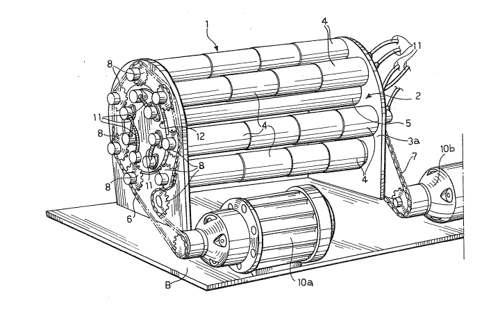
Figure 1 is a general perspective view of the core of a
device formed according to the invention,
Figure 2 is a plan view of the same device (with
various parts removed for clarity) showing the
formation of the pipes in greater detail,
Figure 3 is an end view taken on the arrow III of
Figure 2,
Figure 4 is a section taken on the line IV-IV of Figure
2, and
Figure 5 is a view taken on the line V-V of Figure 2.
In the drawings, a device for manufacturing pipes is
generally indicated 1. In particular, the device
shown by way of example is intended for producing
large-diameter pipes (for example, for use in the
building industry or for the construction of drains)
having a laminated wall structure made from strips of
plastics material or the like, possibly including
recycled and/or formulated plastics material.
The main core of the device 1 is constituted by a
generally cylindrical cage 2 with rollers which is
~' ~ . ':
2~7~3
constituted, in practice, by two end plates, an
upstream or input plate 3a and a downstream or output
plate 3b (with reference to the direction of advance of
the pipes being formed), which are kept in vertical
positions on a base B and between which extend two
concentric sets of rollers, which are also generally
cylindrical; more precisely, there is an outer set of
rollers 4 and an inner set of rollers 5.
In the embodiment illustrated (see Figure 3 in
particular), each set includes seven rollers (however,
this number should be considered purely as an example)
arxanged so as to form seven pairs of homologous
rollers, each pair including a roller of the outer set
4 and a roller of the inner set 5 which face each other
so as together to define a space (a nip) for taking in
the material which is wound up to form the pipe.
As can better be seen in Figures 1, 3 and 5, the
rollers of the two sets 4, 5 are mounted on the plates
3a, 3b with the interposition of bearings which can
oscillate relative to the plates 3a, 3b, the rollers
being driven by respective chains 6 and 7 which pass
around sprockets 8 and 9 mounted on the ends of the
shafts of the rollers which project outwardly from the
end plates 3a, 3b through the bearings. The chains
are driven by respective drive units, indicated lOa and
lOb which are i~dependent of each other so that the
speeds of the two sets of rollers 4 and 5 can be varied
separately.
Moreover, it will be noted (see Figure 1) that the
shafts of the rollers (which are generally hollow) are
connected to distribution pipes 11, through which a
cooling fluid coming from a pump (not shown) can be
:;
.
~7~3
circulated within the rollers 4 and 5 to cool them.
The rollers 4 and 5 thus rotate about respective fixed
axes identified by the positions in which the shafts of
the rollers are mounted on the end plates 3a and 3b.
~s stated, the cage ~ and the two sets of rollers 4 and
are generally cylindrical; an important
characteristic of the solution according to the
invention is that the shafts of the rollers 4 and 5,
and hence their axes of rotation, are not oriented
exactly along the generatrices (or the central axis) of
the cage 2 but are inclined slightly to the
generatrices~ for example, at an angle of the order of
1-2, as can clearly be seen in the end view of Figure
3 (which is taken from the downstream end of the cage
2~ in which the broken lines with single dots indicate
the outlines of the upstream ends of the rollers 4 and
5, that is, those situated adjacent the plate 3a, and
the broken lines with double dots indicate the outlines
of their opposite ends adjacent the plate 3b.
In practice, the situation described is essentially
comparable to the situation which would occur if,
starting from an initial condition in which the axes of
the rollers 4 and 5 are aligned with the generatrices
and the central a~is of the cage 2, the downstream
plate 3b were rotated theoretically relative to the
upstream plate 3a through a certain angle (for example,
an angle of 10 in the case of a cage having a diameter
- measured between the two sets of rollers - of the
order of 300-320 mm and a length of the order of one
metre)~
The "twistlng" of the rollers 4 and 5 is preferably
~: :
,, , ~,
5 3
such that, in eaGh pair of facing rollers, whereas
their upstream ends (situated in correspondence with
the plate 3a) are aligned precisely on a radius of the
cage, their downstream ends (situated in correspondence
with the plate 3b) are aligned on a line which does not
pass exactly through the centre of the cage 2, the
inner roller S being slightly upstream of the
corresponding outer roller 4 (with reference to the
sense in which the pipe is wound onto the cage 2).
In operation:
- the sense of rotation of the rollers 4 and 5
(naturally, the homologous rollers of each pair are
rotated in opposite senses so that the mutually facing
portions of each roller of the outer set 4 and of the
corresponding roller of the inner set 5 move in the
same direction) - on the one hand - and
- the orientation of the angle of inclination of the
axes of the rollers 4, 5 to the generatrices of the
cage 2 - on the other hand -
are selected in a coordinated manner so that any stripelement Wl supplied towards the cage 2, as shown
schematically in Figure 3, in a direction generally
tangential to the cage 2 or, more precisely, a strip Wl
intxoduced into the gripping space (the nip) between
two homologous rollers, one belonging to the outer set
4 and the other belonging to the inner set 5, will be
wound generally around the rollers 5 of the inner set
with a winding movement which, in addition to its
circular or tangential component, also has an axial
component (relative to the cage 2) which results in a
generally translatory movement in the direction of
207~3
advance towards the output end of the cage (the plate
3b).
In the specific case to whîch the end view of Figure 3
relates, the rollers 4 and 5 are assumed to be rotated
in senses which correspond to the movement of the s-trip
W1 from left to right and hence to the winding of the
strip W1 clockwise around the rollers of the cage 2.
In this case, the inclination of the axes of the
rollers 4, 5 is selected so that, if they are observed
from the upstream end of the cage, their downstream
ends are displaced slightly clockwise relative to their
upstream ends, that is, in a complementary manner,
(from the viewpoint of Figure 3) so that, if they are
observed from the downstream end of the cage 2, the
downstream ends of the rollers 4, 5 are displaced
slightly anticlockwise relative to their upstream ends.
As a result of this arrangement, the strip W1 is not
wound in a circle between the rollers 4, 5 but along a
helical path, the pitch of which is related to the
angle at which the rollers 4, 5 are inclined to the
generatrices of the cage 2.
As the rollers 4, 5 rotate, the strip W1 thus gives
rise to a cylindrical body, that is, a pipe P (Figure
2) which advances along the cage 2 from its upstream
end (the plate 3a) to its downstream end (the plate
3b). Therefore, the end plate 3b at the downstream
end has an annular hole 12 through which the pipe P
thus formed can emerge from the cage and be sent, for
example, to a cooling bath in a tank 14 (see Figure 4)
through which the pipe formed, generally indicated P,
advances axially on two support rollers 15.
2 ~ 3
The cooling is necessary, amongst other things, because
the strip Wl usually emerges from a die or extruder Tl
and is therefore at a fairly high temperature; its
temperature is, in any case, controlled (for example,
being kept at around 120-200C during the winding
process) by the cooling effect of the rollers 4 and 5.
This all enables a more intimate connection (seal)
between successive turns of the pipe P being formed,
providing the pipe P with intrinsic mechanical strength
and at the same time ensuring that the strip Wl does
not stick to the rollers 4, 5 and that the material
being wound is not too soft.
The rollers 4 and 5 may be of uniform diameter,
particularly if a pipe P is to be formed from a single
strip Wl wound in a helix.
In the embodiment shown (which relates to a device l
for manufacturing a pipe P with walls having a
laminated structure, that is, a pipe produced by the
helical winding of several strips), the rollers of the
inner set 5 are of unlform diameter whereas the
diameters of the rollers of the outer set 4 become
smaller from the input end of the cage 2 towards its
output end. In particular, each roller 4 may be
considered as being divided theoretically into four
successive portions 41, 42, 43 and 44 wi-th g~h~lly ~ste~ise
or continuously~ decreasing diameters so tha-t-the widths o~ the intake
spaces (the nips) created with respect to the
corresponding inner rollers 5 increase in steps.
In the embodiment illustrated, the device is intended
for forming a laminated pipe from:
- a first strip Wl of plastics material, for example,
2~7~
high-density polyethylene about 2 mm thick, to form the
innermost layer of the pipe,
- a second strip W2 made, for example, of a plastics
material different from that of the first layer Wl;
this may be at least partially recycled plastics
material (if appropriate, including non-thermoplastics
materials as fillers or reinforcing structures~ which
is intended to be wound together with a further
reinforcing strip W20 (for example, a fibre fabric,
wire mesh, etc.); for example, the strip W2 may be 5
mm thick;
a third strip W3 constituted, for example, by a
further plastics material produced by the recycling of
waste plastics materials, and
- a further strip W4 which is narrower (measured
axially of the winding path) and, in practice, is
intended to form generally helical screw threads spaced
at certain intervals on the outer surface of the pipe
P.
As already stated, the strips Wl, W2, W3 and W4 are
usually supplied at a certain temperature from
respective sources Tl, T2, T3 and T4 which may even be
constituted ~y extrusion heads or dies. In the case
of the additional reinforcing material W20, the source
T20 may be constituted, for example, by a reel from
which the material is unwound. In this solution, it
seems preferable, for example, for the strip W20 to be
made of a woven material or mesh, for example, wire
reinforcement mesh, or simply a metal wire or band.
As stated, winding at this temperature enables a
,
,
.. ..
2~7~3
connection to be formed between successive layers of
the wall of the tube. If the nature of the material
and/or the temperature of the process are not such as
to enable or ensure the desired firm connection, the
device 1 may include means for applying adhesives
and/or glues between the layers which are wound
successively onto the cage 2.
The presence of the outer thread W4 on the pipes formed
according to the invention facilitates their connection
by threaded rings. In particular, the ring (which has
an internal thread complementary to the thread W4 on
the pipe P) may be screwed fully onto the end of one of
the pipes to be connected and the end of the other pipe
then brought up to the ring. At this point, the ring
is unscrewed from the first pipe and screwed onto the
end of the other pipe so as to connect the two pipes.
This connection may be further reinforced by a rotary
movement of one of the pipes to advance it sli~htly
inwardly of the ring; this is in accordance with the
method currently used for connecting the ends of
threaded pipes in hydraulic systems.
Naturally, the principle of the invention remaining the
same, the details of construction and forms of
embodiment may be varied widely with respect to those
desecribed and illustrated, withou~ thereby departing
from the scope of the present invention.
,,, ,., , ~ : :
: .