Note: Descriptions are shown in the official language in which they were submitted.
GR ~1 P 7028
HEATING DEVICE FOR ~lY~US~G MEDIA
Speci ~ication:
The present invention relates to a heating device for heatlny
flowing media, includiny a h~at exchanger being heated by PI'C
resistors and being formed of thermally conductlve metal, the
heat exchanger having a slit like pocket formed therein, and
a cuboid substrate body for PTC r~sistors having a shape
adapted to the pocket, the substrate body having recesses on
opposed surfaces for receiving the PTC resistors and an
internal conduit for receiving a contact spring, so that upon
introduction of th~ substrate body into the pocket with khe
PTC resistors located in its recesses, the PTC resistors are
pressed against surfaces of the pocket that ~ace one another.
A heating device of the above-described type is known from
German Published, Non-Prosecuted Application DE 40 13 212 A1.
In such a h~ating device, PTC resistoxs for heatin~ a heat
exchanger can be inserted directly, or by means o~ a sub-
strate body, into a pocket in a metal body serving as a heat
exchanger. A spring introduced between the PTC resistors
presses a surface of each of them having a metal contact
coating, against an associated surface o~ the metal body. In
each case, the spring engages the other metal contact coat-
ing, so that the electrical connection of ths PTC resistors
is effecte.d ~hrough the metal body forming l;he heat exchanger
on one sid~, and the spring on the other.
In the heating d~vic~ known from Gel-man Publish~d, Non-Prose-
cuted Application DE 40 13 21~ A1, the pocket for rec~iving
the PTC resistors in the metal body acting as a heat exchang-
er, has a rectangular cross section. When the PTC resistors
are inserted into the pocket, the metal contact coatings of
the PTC resistors therefore rub against the as~oaiated
surfac~s of the pocket, so that there is a dang~r o~ abrasion
of the metal contact coatings and thus of an inadequate
electrical contact between the PTC resistors and the metal
body.
It is accordingly an object of the invention to provide a
heating device for heatillg flowing media, which overcomes the
hereinafore-mentioned disadvantayes of the heretofore-known
devices of this general type and which improves a heating
device o~ the known type in such a way.,.that upon insertion of
PTC resistors into the pocket of the heat exchanger, abrasion
of the metal contact coatings of the PTC resistors is avoid~-
ed.
With the foregoing and other objects in view there is provid-
ed, in accordance with the invention, a heating device f`or
heating flowing media, comprising a heat exchanger to be
heated by PTC resistors, the heat exchanger being formed of
:.
-2-
7.~
thermally conductive met~l having a sllt-like pocket ~o:rm~d
therein defining a given shape and definirlg pocket surface~
faciny one another, and a cuboid substrate body having a
shape adapted to the given ~hape and haviny an introduction
side to be introduced into the pocket, the substrate body
having opposed surfaces with recesses formed therein for
receiving the PTC resistors and having an internal conduit
formed therein for receiving a contact spring, at lea~t the
surfaces of the substrate body having the recesse6 and the
pocket surfaces facing the surfaces of the substrate body
beiny beveled for decreaslng thQ cro~s section o~ the sub-
strate body and of the pocket from the introduction side
inward, and for pressing the PTC resi~tors again~t the pocket
surfaces upon introduction of the substrat~ body into the
pocket with the PTC resistors located in the recesses.
Other features which are considered as characteristic for the
invention are set forth in the appended claims.
.,.
Although the invention is illustrated and described herein as
embodied in a heating device for heating flowing media, it is
nevertheless not intended to be limited to the detail~ shown,
since various modiications and structural changes may be
made therein without departing from the spirit o~ the inven-
tion and within the scope and range of equivalents of the
claims.
-3-
The construction and method o~ operation Oe the invention,
however, toyether wi~h ad~itional object~ and adv~nt~lge~
thereo~ will be best understood from the followiny descrip-
tion o~ specific embodiments when read in connection with the
accompanying drawings.
Fig. 1 is a diagrammatic, ~ide elevational view o~ a metal
body serving as a heat exchanger, as seen ~rom a ~id~ t.oward
which a pocket for receiving PTC resistors opens; and
Fiys. 2 and 3 are respective side-elevational and pe~spectiv~
views of a substrate body for PTC resistors that can ~e
inserted into the pocket of the metal body of Fig. 1.
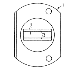
~eferring now to the figures of the drawing in detail and
first, particularly, to Fig. 1 thereof, there is seen a
pocket 2 for receiving a substrate body 4 ~or PTC resistors,
which is provided in a metal body 1 that is intended as a
heat exchanger for a heating device.for heating flowing
media. The metal body 1 has opposed surfaces 3 at the pocket
2, which are beveled in a direction at right angles to the
plane of the drawin~, in such a way that the cross s~ction of
the pocket 2 decreases inwardly from the insertion side
located in the plane of the drawing, at right angles to the
plane of the drawing. The substrate body 4 for PTC resis-
tors, as shown in Figs. 2 and 3, may be made of plastic and
has surfaces 5 with suitable beveling, oriented toward the
--4--
f ~ 3
surfaces 3 o~ the metal body 1. The substrate body 4 can be
insarted into the metal body 1 at right anyles to ~he plane
of the drawing as seen in Fig. 1, by the end thereo~ having
the smaller cross section.
The cuboid substrate body 4 is provided with recessPs 6 on
oppos~d side~ o~ the surfaces 5, for receiving non-illustrat-
ed disk-shaped PTC resistors. An opening 7 is provided in
the region or vicinity of these recesses 6, so that a non~
lustrated contact spriny can be thrust through a conduit 8
between the PTC resistor~ located in the recesse~ 6. After
the introduction of the substrate body 4 into the pockst 2 of
the metal body 1, the contact spring presses the PTC resis-
tors against the surfaces 3 of the mekal body 1 at the pocket
2 and effects the electrical contact thereof. ~lowever, it is
also possible to inject a spring and a contact pin into the
substrate body 4, in order to press the PTC resistors into
the pocket 2 and provide the electrical contact thereof.
This possibility is not shown separately. It will be under-
stood from the above-described embodiment of the metal body 1
and the substrate body ~, that metal contact coatings of the
PTC resistors located in the recesses 6 cannot rub against
the surfaces 3 as they are inserted into the pocket 2 of the
metal body 1, because they practically do not come into
contact with the surfaces 3 until after the substrate body 4
has been ~ully inserted into the pocket 2. Therefore, not
only is there an avoidance of abrasion of metal contact
.:
-5-
~oatings of the PTC re~sistors on -th~ sur~aces 3 of th~ metal
bo~y 1 at the pocket ~, but khe ~'~C resistors are also
pressed agai~st these surfaces with relatively great pres-
sure .
6--