Language selection

Search

Patent 2075863 Summary

Third-party information liability

Some of the information on this Web page has been provided by external sources. The Government of Canada is not responsible for the accuracy, reliability or currency of the information supplied by external sources. Users wishing to rely upon this information should consult directly with the source of the information. Content provided by external sources is not subject to official languages, privacy and accessibility requirements.

Claims and Abstract availability

Any discrepancies in the text and image of the Claims and Abstract are due to differing posting times. Text of the Claims and Abstract are posted:

  • At the time the application is open to public inspection;
  • At the time of issue of the patent (grant).
(12) Patent: (11) CA 2075863
(54) English Title: SYNCHRONOUS DRIVE BELT WITH OBLIQUE AND OFFSET TEETH
(54) French Title: COURROIE D'ENTRAINEMENT SYNCHRONE A DENTS OBLIQUES ET DECALEES
Status: Term Expired - Post Grant Beyond Limit
Bibliographic Data
(51) International Patent Classification (IPC):
  • F16G 5/20 (2006.01)
  • F16G 1/28 (2006.01)
(72) Inventors :
  • GREGG, MICHAEL J. W. (United States of America)
(73) Owners :
  • VEYANCE TECHNOLOGIES, INC.
(71) Applicants :
(74) Agent: MARKS & CLERK
(74) Associate agent:
(45) Issued: 1998-09-15
(22) Filed Date: 1992-08-12
(41) Open to Public Inspection: 1993-11-30
Examination requested: 1993-07-12
Availability of licence: N/A
Dedicated to the Public: N/A
(25) Language of filing: English

Patent Cooperation Treaty (PCT): No

(30) Application Priority Data:
Application No. Country/Territory Date
890,203 (United States of America) 1992-05-29

Abstracts

English Abstract


A synchronous drive belt has at least two
adjacent rows of teeth which are at oppositely
balanced oblique angles to the longitudinal direction
of the belt. In addition, the centerlines of the
teeth in the adjacent rows are offset from each other
by a distance of up to 10% to 90% of their pitch.


French Abstract

Courroie d'entraînement synchrone présentant au moins deux rangées adjacentes de dents qui sont disposées à angles obliques équilibrés opposés au sens longitudinal de la courroie. De plus, les axes centraux des dents des rangées adjacentes sont décalés les uns par rapport aux autres d'une distance allant de 10 à 90 % de leur inclinaison.

Claims

Note: Claims are shown in the official language in which they were submitted.

THE EMBODIMENTS OF THE INVENTION IN WHICH AN EXCLUSIVE
PROPERTY OR PRIVILEGE IS CLAIMED ARE DEFINED AS FOLLOWS:
1. A synchronous drive belt comprised of a resilient
elastomer, reinforced with one or more reinforcing members
extending along and thereby defining a pitch line, with at least
two transversely adjacent rows of teeth having centerlines
uniformly spaced apart in the longitudinal direction by their
Pitch P and extending obliquely to the longitudinal direction such
that the teeth in the transversely adjacent rows are at oppositely
balanced angles and the centerlines of said adjacent teeth are
offset from each other by a distance of from 10% to 90% of the
Pitch P.
2. The belt according to claim 1 wherein the oblique angle
is from 15° to 45°.
3. The belt according to claim 1 wherein the centerlines of
the transversely adjacent teeth are offset from each other by a
distance of from 40% to 60% of the Pitch P.
4. The belt according to claim 3 wherein the offset is 50%
of the Pitch P.

5. A synchronous drive pulley comprising a series of
pulley teeth evenly spaced apart in the circumferential
direction by a Pitch P and having defined between said teeth
pulley cavities; said cavities being adapted to receive
complementary teeth of a belt having at least two transversely
adjacent rows of teeth having centerlines uniformly spaced
apart in a longitudinal direction by the Pitch P and extending
obliquely to the longitudinal direction such that said teeth
of said belt in the transversely adjacent rows are at
oppositely balanced angles and said centerlines of said
adjacent teeth of said belt are offset from each other by a
distance from 10% to 90% of the Pitch P.
6. A combination comprising the pulley according to
Claim 5 and said belt.

Description

Note: Descriptions are shown in the official language in which they were submitted.


201S863
SYNCHRONOUS DRIVE BELT WITH OBLIOUE AND OFFSET TEETH
The present invention relates to a synchronous drive belt
designed to minimize noise while in operation.
Backqround of the Invention
Conventional synchronous drive belts have teeth placed at
right angles to the belt mid-circumferential plane such as
illustrated in my prior U. S. Patent Nos. 3,924,481 and 4,108,011.
In such belts the whole tooth then engages with a corresponding
pulley cavity at the same time, in a manner analogous to a rack
and pinion gear. This engagement results in some impact between
the belt and the pulley and causes air to be suddenly expelled
from the pulley cavity. This in turn results in noise. Spectrum
analysis of noise generated by synchronous drive belts typically
shows the dominant frequencies being that of tooth engagement, and
harmonics of that frequency.
United States Patent Nos. 4,679,459 and 4,951,261 illustrate
gear systems having staggered or offset teeth to reduce noise and
wear. U. S. Patent No. 3,033,050 illustrates a belt/pulley
combination wherein the belt has teeth in a herringbone design to
center the belt over a V-shaped cavity of a pulley in order to
preclude axial movement of the belt on the pulley.
A

~ ~3
Summary of the Invention
In accordance with the practice of the present
invention in one aspect thereof, there is provided a
synchronous drive belt comprised of a resilient elastomer,
reinforced with one or more reinforcing members extending
along and thereby defining a pitch line, with at least two
transversely adjacent rows of teeth, having centerlines,
uniformly spaced apart in the longitudinal direction by
their Pitch P and extending obliquely to the longitudinal
direction such that the teeth in the transversely adjacent
rows are at oppositely balanced angles and the centerlines
of said adjacent teeth are offset from each other by a
distance of from 10% to 90% of the Pitch P.
Other aspects of this invention are as follows:
A synchronous drive pulley comprising a series of
pulley teeth evenly spaced apart in the circumferential
direction by a Pitch P and having defined between said
teeth pulley cavities; said cavities being adapted to
receive complementary teeth of a belt having at least
two transversely adjacent rows of teeth having centerlines
uniformly spaced apart in a longitudinal direction by the
Pitch P and extending obliquely to the longitudinal
direction such that said teeth of said belt in the
transversely adjacent rows are at oppositely balanced
angles and said centerlines of said adjacent teeth of said
belt are offset from each other by a distance of from 10%
to 90% of the Pitch P.
A combination comprising the pulley and belt set out
hereinabove.
B

2075863
2a
Brief Description of the Drawings
Figure 1 is a bottom plan view of a portion of a
synchronous drive belt of the present invention.
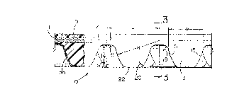
Figure 2 is a side view partly in section taken along
line 2-2 of Figure 1.
Figure 3 is a transverse cross-sectional view of the
belt taken along line 3-3 of Figure 2.
Figure 4 is a side view of a portion of a pulley which
is compatible with the belt of the invention.
Detailed Description of the Invention
The drawings illustrate a synchronous drive belt shown
generally at 10 which is made of a resilient elastomer and
reinforced with a longitudinal tensile member 11 which lies
along the pitch line 12 and is made up usually of a plurality
of cords of a high elastic modulus. These cords may be made
from glass fiber, carbon fiber, steel, polyester, high tenacity
rayon or preferably, polyaramide. The tooth surface 22 may, if
required, be reinforced with an abrasion resistant fabric 29,
an example of which is nylon. The elastomers may be any one
of those known to be suitable for use in such belts, e.g.,
polychloroprene, polyurethane, NBR, IIR, IR, SBR, CSM, EPDM,
other thermosets, thermoplastic elastomers and other polymer
alloys.
The belt 10 has at least two transversely adjacent rows
of teeth 13, having centerlines 13a and

207~8~
-- 3
13b. The teeth 13 are uniformly spaced apart in the
longitudinal direction by their Pitch P and extend
obliquely to the longitudinal direction such that the
teeth 13 in the transversely adjacent rows are at
oppositely balanced angles 17 and the centerlines 13a
and 13b are offset from each other by a distance 21 of
from 10~ to 90~ of the Pitch P. Preferably, the
offset ranges from 40~ to 60~ of the Pitch P.
Optimally, the offset distance is 50~ of the Pitch P.
The oblique angle 17 can range from 15~ to 45~.
Each tooth 13 has fore and aft flank surfaces
15,15 which describe an arc having a radius R whose
center is illustrated at the junction of the pitch
line 12 and midway between adjacent teeth. It can be
appreciated, however, that the center of the radius R
can be located at different points, e.g., as are
taught by my previously mentioned prior patents. The
length of the radius R is generally about 70~ to 90
of the Pitch P. The width of the tooth W is
determined by the length of the radius R and its
center point. The belt tooth height 14 is about 30
to about 55~ of the Pitch P. To provide smooth
transitions between the belt flanks 15 and the land
area defined as the surface between the teeth, there
is provided a belt tooth root radius 18. The belt
tooth tip blend radius 20 provides-6Xamooth transition
between the belt flank 15 and the belt tooth tip 22.
While not a necessity, it is useful to construct the
belt so that the adjacent rows of teeth 13 are
separated by a gap 23 in order to reduce frictional
disengagement from the pulley cavities 26.
The pulley shown generally at 24 has a series of
complimentary teeth 25 evenly spaced apart by the
Pitch P. The space between the teeth 25 defines the
cavity 26 having a cavity base 27. The cavity 26 has
fore and aft flank surfaces which describe an arc

~07~863
having a radius R' which is equal to or greater than
the belt tooth flank radius R. The cavity depth 34
can be from 85% to 105% of the belt tooth depth 14.
The center of the radius R' is shown at the
intersection of a pulley tooth radial centerline 30
and the pitch circle 28 which defines an imaginary
line which is beyond the outer radius of the pulley
tooth by the pitch line differential 16 which
corresponds to the distance between the land area
between the belt teeth and the pitch line 12.
The cavity base 27 can be flat or it can be an
arc of a circle having a radius 32 which is located
below the cavity base 27. Smooth transitions from the
cavity flanks to the pulley tooth tip and to the
cavity base are provided by the pulley tooth tip blend
radius 36 and the pulley cavity base blend radius 38
respectively.
The pulleys may be made from metal, thermoplastic
or thermosetting materials. Optionally, the belts of
the invention may be provided with additional
transverse rigidity by transverse reinforcement 19.
While certain representative embodiments and
details have been shown for the purpose of
illustrating the invention, it will be apparent to
those skilled in this art that various changes and
modifications may be made therein without departing
from the spirit or scope of the invention.

Representative Drawing
A single figure which represents the drawing illustrating the invention.
Administrative Status

2024-08-01:As part of the Next Generation Patents (NGP) transition, the Canadian Patents Database (CPD) now contains a more detailed Event History, which replicates the Event Log of our new back-office solution.

Please note that "Inactive:" events refers to events no longer in use in our new back-office solution.

For a clearer understanding of the status of the application/patent presented on this page, the site Disclaimer , as well as the definitions for Patent , Event History , Maintenance Fee  and Payment History  should be consulted.

Event History

Description Date
Inactive: Expired (new Act pat) 2012-08-12
Letter Sent 2009-06-26
Inactive: IPC from MCD 2006-03-11
Grant by Issuance 1998-09-15
Inactive: Final fee received 1998-05-11
Pre-grant 1998-05-11
Notice of Allowance is Issued 1997-11-19
Letter Sent 1997-11-19
Inactive: Application prosecuted on TS as of Log entry date 1997-11-13
Inactive: Status info is complete as of Log entry date 1997-11-13
Inactive: First IPC assigned 1997-11-05
Inactive: IPC removed 1997-11-05
Inactive: IPC assigned 1997-11-05
Inactive: Approved for allowance (AFA) 1997-11-05
Application Published (Open to Public Inspection) 1993-11-30
All Requirements for Examination Determined Compliant 1993-07-12
Request for Examination Requirements Determined Compliant 1993-07-12

Abandonment History

There is no abandonment history.

Maintenance Fee

The last payment was received on 

Note : If the full payment has not been received on or before the date indicated, a further fee may be required which may be one of the following

  • the reinstatement fee;
  • the late payment fee; or
  • additional fee to reverse deemed expiry.

Please refer to the CIPO Patent Fees web page to see all current fee amounts.

Owners on Record

Note: Records showing the ownership history in alphabetical order.

Current Owners on Record
VEYANCE TECHNOLOGIES, INC.
Past Owners on Record
MICHAEL J. W. GREGG
Past Owners that do not appear in the "Owners on Record" listing will appear in other documentation within the application.
Documents

To view selected files, please enter reCAPTCHA code :


To view images, click a link in the Document Description column. To download the documents, select one or more checkboxes in the first column and then click the "Download Selected in PDF format (Zip Archive)" or the "Download Selected as Single PDF" button.

List of published and non-published patent-specific documents on the CPD .

If you have any difficulty accessing content, you can call the Client Service Centre at 1-866-997-1936 or send them an e-mail at CIPO Client Service Centre.


Document
Description 
Date
(yyyy-mm-dd) 
Number of pages   Size of Image (KB) 
Cover Page 1994-02-19 1 17
Abstract 1994-02-19 1 13
Claims 1994-02-19 2 48
Drawings 1994-02-19 2 75
Description 1994-02-19 5 187
Cover Page 1998-08-25 1 34
Description 1997-10-17 5 185
Claims 1997-10-17 2 46
Representative drawing 1998-08-25 1 8
Commissioner's Notice - Application Found Allowable 1997-11-19 1 165
Correspondence 1998-05-11 1 58
Correspondence 2008-10-24 1 19
Fees 1996-06-25 1 53
Fees 1995-06-23 1 59
Fees 1994-06-24 2 92
Courtesy - Office Letter 1993-08-17 1 36
Prosecution correspondence 1993-07-12 1 24
Prosecution correspondence 1997-09-12 2 39
Prosecution correspondence 1993-07-13 2 43
Prosecution correspondence 1996-04-29 3 65
Prosecution correspondence 1997-01-13 1 38
Examiner Requisition 1996-12-10 1 49
Prosecution correspondence 1993-07-20 1 30
Examiner Requisition 1996-03-01 2 61
Examiner Requisition 1997-07-15 1 26