Sélection de la langue

Search

Sommaire du brevet 2075863 

Énoncé de désistement de responsabilité concernant l'information provenant de tiers

Une partie des informations de ce site Web a été fournie par des sources externes. Le gouvernement du Canada n'assume aucune responsabilité concernant la précision, l'actualité ou la fiabilité des informations fournies par les sources externes. Les utilisateurs qui désirent employer cette information devraient consulter directement la source des informations. Le contenu fourni par les sources externes n'est pas assujetti aux exigences sur les langues officielles, la protection des renseignements personnels et l'accessibilité.

Disponibilité de l'Abrégé et des Revendications

L'apparition de différences dans le texte et l'image des Revendications et de l'Abrégé dépend du moment auquel le document est publié. Les textes des Revendications et de l'Abrégé sont affichés :

  • lorsque la demande peut être examinée par le public;
  • lorsque le brevet est émis (délivrance).
(12) Brevet: (11) CA 2075863
(54) Titre français: COURROIE D'ENTRAINEMENT SYNCHRONE A DENTS OBLIQUES ET DECALEES
(54) Titre anglais: SYNCHRONOUS DRIVE BELT WITH OBLIQUE AND OFFSET TEETH
Statut: Durée expirée - au-delà du délai suivant l'octroi
Données bibliographiques
(51) Classification internationale des brevets (CIB):
  • F16G 5/20 (2006.01)
  • F16G 1/28 (2006.01)
(72) Inventeurs :
  • GREGG, MICHAEL J. W. (Etats-Unis d'Amérique)
(73) Titulaires :
  • VEYANCE TECHNOLOGIES, INC.
(71) Demandeurs :
(74) Agent: MARKS & CLERK
(74) Co-agent:
(45) Délivré: 1998-09-15
(22) Date de dépôt: 1992-08-12
(41) Mise à la disponibilité du public: 1993-11-30
Requête d'examen: 1993-07-12
Licence disponible: S.O.
Cédé au domaine public: S.O.
(25) Langue des documents déposés: Anglais

Traité de coopération en matière de brevets (PCT): Non

(30) Données de priorité de la demande:
Numéro de la demande Pays / territoire Date
890,203 (Etats-Unis d'Amérique) 1992-05-29

Abrégés

Abrégé français

Courroie d'entraînement synchrone présentant au moins deux rangées adjacentes de dents qui sont disposées à angles obliques équilibrés opposés au sens longitudinal de la courroie. De plus, les axes centraux des dents des rangées adjacentes sont décalés les uns par rapport aux autres d'une distance allant de 10 à 90 % de leur inclinaison.


Abrégé anglais


A synchronous drive belt has at least two
adjacent rows of teeth which are at oppositely
balanced oblique angles to the longitudinal direction
of the belt. In addition, the centerlines of the
teeth in the adjacent rows are offset from each other
by a distance of up to 10% to 90% of their pitch.

Revendications

Note : Les revendications sont présentées dans la langue officielle dans laquelle elles ont été soumises.


THE EMBODIMENTS OF THE INVENTION IN WHICH AN EXCLUSIVE
PROPERTY OR PRIVILEGE IS CLAIMED ARE DEFINED AS FOLLOWS:
1. A synchronous drive belt comprised of a resilient
elastomer, reinforced with one or more reinforcing members
extending along and thereby defining a pitch line, with at least
two transversely adjacent rows of teeth having centerlines
uniformly spaced apart in the longitudinal direction by their
Pitch P and extending obliquely to the longitudinal direction such
that the teeth in the transversely adjacent rows are at oppositely
balanced angles and the centerlines of said adjacent teeth are
offset from each other by a distance of from 10% to 90% of the
Pitch P.
2. The belt according to claim 1 wherein the oblique angle
is from 15° to 45°.
3. The belt according to claim 1 wherein the centerlines of
the transversely adjacent teeth are offset from each other by a
distance of from 40% to 60% of the Pitch P.
4. The belt according to claim 3 wherein the offset is 50%
of the Pitch P.

5. A synchronous drive pulley comprising a series of
pulley teeth evenly spaced apart in the circumferential
direction by a Pitch P and having defined between said teeth
pulley cavities; said cavities being adapted to receive
complementary teeth of a belt having at least two transversely
adjacent rows of teeth having centerlines uniformly spaced
apart in a longitudinal direction by the Pitch P and extending
obliquely to the longitudinal direction such that said teeth
of said belt in the transversely adjacent rows are at
oppositely balanced angles and said centerlines of said
adjacent teeth of said belt are offset from each other by a
distance from 10% to 90% of the Pitch P.
6. A combination comprising the pulley according to
Claim 5 and said belt.

Description

Note : Les descriptions sont présentées dans la langue officielle dans laquelle elles ont été soumises.

201S863
SYNCHRONOUS DRIVE BELT WITH OBLIOUE AND OFFSET TEETH
The present invention relates to a synchronous drive belt
designed to minimize noise while in operation.
Backqround of the Invention
Conventional synchronous drive belts have teeth placed at
right angles to the belt mid-circumferential plane such as
illustrated in my prior U. S. Patent Nos. 3,924,481 and 4,108,011.
In such belts the whole tooth then engages with a corresponding
pulley cavity at the same time, in a manner analogous to a rack
and pinion gear. This engagement results in some impact between
the belt and the pulley and causes air to be suddenly expelled
from the pulley cavity. This in turn results in noise. Spectrum
analysis of noise generated by synchronous drive belts typically
shows the dominant frequencies being that of tooth engagement, and
harmonics of that frequency.
United States Patent Nos. 4,679,459 and 4,951,261 illustrate
gear systems having staggered or offset teeth to reduce noise and
wear. U. S. Patent No. 3,033,050 illustrates a belt/pulley
combination wherein the belt has teeth in a herringbone design to
center the belt over a V-shaped cavity of a pulley in order to
preclude axial movement of the belt on the pulley.
A

~ ~3
Summary of the Invention
In accordance with the practice of the present
invention in one aspect thereof, there is provided a
synchronous drive belt comprised of a resilient elastomer,
reinforced with one or more reinforcing members extending
along and thereby defining a pitch line, with at least two
transversely adjacent rows of teeth, having centerlines,
uniformly spaced apart in the longitudinal direction by
their Pitch P and extending obliquely to the longitudinal
direction such that the teeth in the transversely adjacent
rows are at oppositely balanced angles and the centerlines
of said adjacent teeth are offset from each other by a
distance of from 10% to 90% of the Pitch P.
Other aspects of this invention are as follows:
A synchronous drive pulley comprising a series of
pulley teeth evenly spaced apart in the circumferential
direction by a Pitch P and having defined between said
teeth pulley cavities; said cavities being adapted to
receive complementary teeth of a belt having at least
two transversely adjacent rows of teeth having centerlines
uniformly spaced apart in a longitudinal direction by the
Pitch P and extending obliquely to the longitudinal
direction such that said teeth of said belt in the
transversely adjacent rows are at oppositely balanced
angles and said centerlines of said adjacent teeth of said
belt are offset from each other by a distance of from 10%
to 90% of the Pitch P.
A combination comprising the pulley and belt set out
hereinabove.
B

2075863
2a
Brief Description of the Drawings
Figure 1 is a bottom plan view of a portion of a
synchronous drive belt of the present invention.
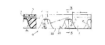
Figure 2 is a side view partly in section taken along
line 2-2 of Figure 1.
Figure 3 is a transverse cross-sectional view of the
belt taken along line 3-3 of Figure 2.
Figure 4 is a side view of a portion of a pulley which
is compatible with the belt of the invention.
Detailed Description of the Invention
The drawings illustrate a synchronous drive belt shown
generally at 10 which is made of a resilient elastomer and
reinforced with a longitudinal tensile member 11 which lies
along the pitch line 12 and is made up usually of a plurality
of cords of a high elastic modulus. These cords may be made
from glass fiber, carbon fiber, steel, polyester, high tenacity
rayon or preferably, polyaramide. The tooth surface 22 may, if
required, be reinforced with an abrasion resistant fabric 29,
an example of which is nylon. The elastomers may be any one
of those known to be suitable for use in such belts, e.g.,
polychloroprene, polyurethane, NBR, IIR, IR, SBR, CSM, EPDM,
other thermosets, thermoplastic elastomers and other polymer
alloys.
The belt 10 has at least two transversely adjacent rows
of teeth 13, having centerlines 13a and

207~8~
-- 3
13b. The teeth 13 are uniformly spaced apart in the
longitudinal direction by their Pitch P and extend
obliquely to the longitudinal direction such that the
teeth 13 in the transversely adjacent rows are at
oppositely balanced angles 17 and the centerlines 13a
and 13b are offset from each other by a distance 21 of
from 10~ to 90~ of the Pitch P. Preferably, the
offset ranges from 40~ to 60~ of the Pitch P.
Optimally, the offset distance is 50~ of the Pitch P.
The oblique angle 17 can range from 15~ to 45~.
Each tooth 13 has fore and aft flank surfaces
15,15 which describe an arc having a radius R whose
center is illustrated at the junction of the pitch
line 12 and midway between adjacent teeth. It can be
appreciated, however, that the center of the radius R
can be located at different points, e.g., as are
taught by my previously mentioned prior patents. The
length of the radius R is generally about 70~ to 90
of the Pitch P. The width of the tooth W is
determined by the length of the radius R and its
center point. The belt tooth height 14 is about 30
to about 55~ of the Pitch P. To provide smooth
transitions between the belt flanks 15 and the land
area defined as the surface between the teeth, there
is provided a belt tooth root radius 18. The belt
tooth tip blend radius 20 provides-6Xamooth transition
between the belt flank 15 and the belt tooth tip 22.
While not a necessity, it is useful to construct the
belt so that the adjacent rows of teeth 13 are
separated by a gap 23 in order to reduce frictional
disengagement from the pulley cavities 26.
The pulley shown generally at 24 has a series of
complimentary teeth 25 evenly spaced apart by the
Pitch P. The space between the teeth 25 defines the
cavity 26 having a cavity base 27. The cavity 26 has
fore and aft flank surfaces which describe an arc

~07~863
having a radius R' which is equal to or greater than
the belt tooth flank radius R. The cavity depth 34
can be from 85% to 105% of the belt tooth depth 14.
The center of the radius R' is shown at the
intersection of a pulley tooth radial centerline 30
and the pitch circle 28 which defines an imaginary
line which is beyond the outer radius of the pulley
tooth by the pitch line differential 16 which
corresponds to the distance between the land area
between the belt teeth and the pitch line 12.
The cavity base 27 can be flat or it can be an
arc of a circle having a radius 32 which is located
below the cavity base 27. Smooth transitions from the
cavity flanks to the pulley tooth tip and to the
cavity base are provided by the pulley tooth tip blend
radius 36 and the pulley cavity base blend radius 38
respectively.
The pulleys may be made from metal, thermoplastic
or thermosetting materials. Optionally, the belts of
the invention may be provided with additional
transverse rigidity by transverse reinforcement 19.
While certain representative embodiments and
details have been shown for the purpose of
illustrating the invention, it will be apparent to
those skilled in this art that various changes and
modifications may be made therein without departing
from the spirit or scope of the invention.

Dessin représentatif
Une figure unique qui représente un dessin illustrant l'invention.
États administratifs

2024-08-01 : Dans le cadre de la transition vers les Brevets de nouvelle génération (BNG), la base de données sur les brevets canadiens (BDBC) contient désormais un Historique d'événement plus détaillé, qui reproduit le Journal des événements de notre nouvelle solution interne.

Veuillez noter que les événements débutant par « Inactive : » se réfèrent à des événements qui ne sont plus utilisés dans notre nouvelle solution interne.

Pour une meilleure compréhension de l'état de la demande ou brevet qui figure sur cette page, la rubrique Mise en garde , et les descriptions de Brevet , Historique d'événement , Taxes périodiques et Historique des paiements devraient être consultées.

Historique d'événement

Description Date
Inactive : Périmé (brevet - nouvelle loi) 2012-08-12
Lettre envoyée 2009-06-26
Inactive : CIB de MCD 2006-03-11
Accordé par délivrance 1998-09-15
Inactive : Taxe finale reçue 1998-05-11
Préoctroi 1998-05-11
Un avis d'acceptation est envoyé 1997-11-19
Lettre envoyée 1997-11-19
Inactive : Dem. traitée sur TS dès date d'ent. journal 1997-11-13
Inactive : Renseign. sur l'état - Complets dès date d'ent. journ. 1997-11-13
Inactive : CIB en 1re position 1997-11-05
Inactive : CIB enlevée 1997-11-05
Inactive : CIB attribuée 1997-11-05
Inactive : Approuvée aux fins d'acceptation (AFA) 1997-11-05
Demande publiée (accessible au public) 1993-11-30
Toutes les exigences pour l'examen - jugée conforme 1993-07-12
Exigences pour une requête d'examen - jugée conforme 1993-07-12

Historique d'abandonnement

Il n'y a pas d'historique d'abandonnement

Taxes périodiques

Le dernier paiement a été reçu le 

Avis : Si le paiement en totalité n'a pas été reçu au plus tard à la date indiquée, une taxe supplémentaire peut être imposée, soit une des taxes suivantes :

  • taxe de rétablissement ;
  • taxe pour paiement en souffrance ; ou
  • taxe additionnelle pour le renversement d'une péremption réputée.

Veuillez vous référer à la page web des taxes sur les brevets de l'OPIC pour voir tous les montants actuels des taxes.

Titulaires au dossier

Les titulaires actuels et antérieures au dossier sont affichés en ordre alphabétique.

Titulaires actuels au dossier
VEYANCE TECHNOLOGIES, INC.
Titulaires antérieures au dossier
MICHAEL J. W. GREGG
Les propriétaires antérieurs qui ne figurent pas dans la liste des « Propriétaires au dossier » apparaîtront dans d'autres documents au dossier.
Documents

Pour visionner les fichiers sélectionnés, entrer le code reCAPTCHA :


Pour visualiser une image, cliquer sur un lien dans la colonne description du document. Pour télécharger l'image (les images), cliquer l'une ou plusieurs cases à cocher dans la première colonne et ensuite cliquer sur le bouton "Télécharger sélection en format PDF (archive Zip)" ou le bouton "Télécharger sélection (en un fichier PDF fusionné)".

Liste des documents de brevet publiés et non publiés sur la BDBC .

Si vous avez des difficultés à accéder au contenu, veuillez communiquer avec le Centre de services à la clientèle au 1-866-997-1936, ou envoyer un courriel au Centre de service à la clientèle de l'OPIC.


Description du
Document 
Date
(aaaa-mm-jj) 
Nombre de pages   Taille de l'image (Ko) 
Page couverture 1994-02-19 1 17
Abrégé 1994-02-19 1 13
Revendications 1994-02-19 2 48
Dessins 1994-02-19 2 75
Description 1994-02-19 5 187
Page couverture 1998-08-25 1 34
Description 1997-10-17 5 185
Revendications 1997-10-17 2 46
Dessin représentatif 1998-08-25 1 8
Avis du commissaire - Demande jugée acceptable 1997-11-19 1 165
Correspondance 1998-05-11 1 58
Correspondance 2008-10-24 1 19
Taxes 1996-06-25 1 53
Taxes 1995-06-23 1 59
Taxes 1994-06-24 2 92
Courtoisie - Lettre du bureau 1993-08-17 1 36
Correspondance de la poursuite 1993-07-12 1 24
Correspondance de la poursuite 1997-09-12 2 39
Correspondance de la poursuite 1993-07-13 2 43
Correspondance de la poursuite 1996-04-29 3 65
Correspondance de la poursuite 1997-01-13 1 38
Demande de l'examinateur 1996-12-10 1 49
Correspondance de la poursuite 1993-07-20 1 30
Demande de l'examinateur 1996-03-01 2 61
Demande de l'examinateur 1997-07-15 1 26