Note: Descriptions are shown in the official language in which they were submitted.
2~612~
13DV-10766
8y8~ BT~OD ~O~ P~O~æD l5~ OO~
cP~os~=e~E~5~
Ref~rence i8 made to the following related and
co-pending applications îiled concurrently herewith
and herein incorpc~rated by re:f~rence haYing U. S .
5erial NoO (GE Docket No. 13D~7-9930) and
U.S. Serial N~. (GE Docket No. 13DtT-lû872).
BACKGP~OlJNl) OF TH~ IN~NTIO~
1. Fi~ld OI the In~entic~n
The present inv~ntion relates ts~ cooling syste~Ds
for gas turbin~ ~ngines. Mvr~ particularly, th~
presenlt invention pertainE; to a method and ~y tem sr
~: cooling an engine by utilizing air from th~
intermediate stage o~ a compressor to cool a flow path
adjacent a combustor stag~ leading to a turbine ~;tage.
An improved seal preveslts ~:ubstantial laakage of
c~fnpressor di~charge ~CD~ air ~ro~ entering the flt~w
path. Since the a~ r supplied by the interm~diate
stage compres~or i8 at a lower temperature than CD
air, less volume is needed ~or the sam~ deg:ree o~
coolingO Furtherm:ore, ~3ince less work i8 performed on
th~ air ~upplied by the intersnedi2lte ~tage co;npres~;or"
fu~al e~oi~ncy ~; i~prov~dl and ~uel ce~nsumption
reduced.
: .
;.
.. . ' . . . .
.
2 ~
2 13D~-10766
2. Discussion of the Background
Air leakage through gas turbine engin2 seals may
signi~icantly increase fu~l consumption, reduce engine
efficiency and increase malntenance costs by
increasing turbine inlet temperatures. Gas turbine
~ngines have traditionally included labyrinth seals at
critical sealing locations. ~abyrinth s~als c~ntrol
the leakage o~ high pressure gas, such as compres~or
discharge air, from a gen~rally high pres~ur~ area to
a generally low pressure area. Th~ seals operate ~y
throttlin~ gas flow through a serie~ o~ annular
constrictions formed betwsen annular teath, which may
be located on a rota~ing component, and an annular rub
strip which may be located on a station~y engine
member. The rub ~trips are ~bradable to allow the
teeth ~o rub lightly duri~g dynamic operating
conditions, such as therm~l transients or maneuver
load~. The effecti~eness o~ these labyrinth ~eals i~
depend~nt on keeping the radial clearance hetw~en the
rub strip and teeth to a ~inimum.
However, the minimu~ radial clearance is li~ted
by manufacturing tolerances, rotor concentriGity
control, and thermal and ce~trifugal growths betw~en
rotating and ~tationary components. Too ~all a
radial clearance re~ults in premature seal wear and
po~sible engins d~mag~, while too large a radial
clearance results in exce~s leakaga. A~ ~eal
diamet~rs and ga~ te~perature~ increa~e in ad~an~ed
engines, the radial clearance of labyrinth ~eals ha~
increased~ thereby di~inishing their effectiveness.
Gas bearing ~ace s~als provide an alternativQ to
the labyrinth ~ealO U.S. P~tent 3,383,033 l ~ued to
C. ~o~re and ass~gned to ~h~ assi~nee o~ ~he present
.. . .
. .:.~'. '. ' ' , . ' '
.. . , : :
., . ,: '':
.
:
.
~7~ 2t3
3 13~V-10766
invention discloses a gas bearing face ~eal ~or use as
a compre~sor discharge seal. Although the ~eal as
disclosed may ~e an improvem~nt over the labyrinth
seal, the di~closed seal includes a number of
potential disadvantagesO For example, the disclosed
seal does not include means ~or maintaining the seal
concentric with respect to the axis o~ the englne or
with other seal components. Test analysis has
demonstrated that concentricity of a ring eal with
respect to other seal components i8 i~portant ~or ~ood
seal operation. Concentriaity help~ maintain
concentric, balanced pressure forces on the seal
components and promotes good sealing characteristic~
while allowing for the u~e of s~aller, more
lightweight seal components.
The seal disclosed in U.S. Patenk NoO 3,383,033
uses a r~latively massive ring ~ember and therefore
possesses a high ~ass inertiaO Ideally, the ring
member should hav~ a low ~ass in~rtia and hav~ a
relatively hi~h compliance ~or reduced seal weight
and, more importantly, r~duced hy~teresi~ in the
clearance between the radial sealing surface ~nd the
restricting tooth. A low mass inertia ring member can
more guickly and ef~icie~tly track motion o~ the
sealing ~urface wi~h lower actuating forces~
It is also believed that the seal disclosed in
U.S. P~tent No. 3,383,033 ~ay i~clude ~ propensity ~or
the clearance between the ~eal housing ~nd fac~ o~ th~
seal ring ~ber to vary according to thermal growth
and other factors causing changes in pressure force~
and poor sealing~ Also, ~he disclos~d s~al ~n~lude~
an auxiliary restrict~r tooth which i~ lntegral with
or mounted on th~ rin~ me~ber ~ich ad~s w~ight ~ th~
. .
. ~ .
.
2~7~
4 13D~-10766
ring member requiring heavy spring ~eans tu be uRed to
bias the ring member away from the ~ealing surfac~.
Furthermore, it is believed that the disclosed seal
does not ef~iciently vent air exiting the air bearing
space and the restrictor tooth to the low pressure
region. Improved venting is desired to assure proper
pressure ~alance on the ring me~ber.
The above di~advantages of the seal disclo~ed in
U.S. Patent 3,383,033 are addressed in the U.S. Pat~nt
Application entitled i'Gas Bèaring Sealing ~eansi',
~iled March 25, 1991, having U.S. Serial NoO
,~GE Docket No. 13D~-96113, herein
incorporated by re~erenoe in its entirety~ For
purpose~ of thi6 application, the ~'Gas Bearing SQaling
Means" disclosed in the application filed on March 25,
1991 shall hexQinafter be referred to as the 9limproved
gas bearing seal".
The improved ga~ bearing seal maintain~ a
concentric relationship between gas bearing ~ace seal
components to eætablish concentric pressure forces on
the components. The improved gas bearing ~al ha~ a
~ace seal rin~ member which is pressurized ~n the
radially outward direction in order to maintain rin~
shape. The improved gas bParing seal has a reduced
maes inertia face seal me~ber for reducing sealing
clearance hysteresi~. The improved gas bearing seal
has ~eans for ~aintaining a pre~sure balance even when
the engine ~tationa~y ~tru~ture i8 axposed to
differential growth. Further~ore, the improved ga~
bearing face seal requires l~ss tension in the ~pring
~ means which biases the ~ace sesl member aw~y ~rom the
: ~ealing ~urfac~ and achieve~ i~pro~ed ~low ~rom a gas
~7fii ~
13D~1-10766
bearing face surface and a primary ~low re~trictor
means O
The above features of the improved gas bearing
seal are achieved by a seal as~embly for restricting
5 flow i~rox~ a relatively hiyher pressure region to a
relatively lower pressure region at a lo;:ation whic~
interfaces an engine stationary member and an engine
rotating me~ber. The seal a~sembly of the improv~d
gas bearing seal includes a face ~eal ring member with
10 a primary restrictor sealing dam, housing means
includirlg a housing ~truc:ture fixed to a~ en~ine
stationary stnlcture, and a ~econdary seal means,
which may be a piston ring ~;eal, in sealing engagement
with the housing means and ~ face ~eal ring ~a~er.
15 The face seal ring ~nember i mounted sm the housins7
for movement c~f the primary sealing dam i~to a
predetermined cle~rance with a pri~nary sealin5~ c;urface
on the rotating engine member.
The assembly includes supp~rt Dle~n~ for
20 ~upporting the face ~eal ring memb~r concentric~lly
with respect to a housing sur~ace to ~nai~tain
concerltric sealing forces vn seal romp~nents, while
psrmitting radial growth between the face ~eal ring
mem}:)er and a hous ing struc:turQ . Control ring mean~i
25 concentric:ally positioned on the housing structure may
b~ used in high temperature applications to n~int~i;n
pressure balance on seal components during
difîerential growth of the housin5~ ~tructure ~it~
re~pect to the ~ace ceal ring D~e~bQrO ~e ~3eal
30 assembly ~ay be s::onfigured to utiliz6~ the high
pressure region b~ing ~ealed 'I:Q pressurize t~e ring
member radially outward, for aaintaining ring
roundness. Auxiliary re~tr{ctiTIg te~3th can b~ mounted
~ ,,
- :
;
n
6 13DV-10766
on a structure separate from the face seal member, the
teeth being concentric with respeot to a ~ace seal
member ~urface and a ~urface o~ th~ engine rotating
member. ~enting of the gas bearing space and primary
restrictor ~low ls improved by lncluding a vent
channel turning vane and circumfer~ntially angled vent
passages to reduce the pressure drop from the vent
channel to the l~w pressure region.
The impro~ed yas bearing seal signi~icantly
reduces leakage o compressor di~charge air ~o that
more compressor discharge air i~ utilizsd by the
combustor~ The improved gas bearing seal al50
significantly reduces the temperatur~ rise of the air
that leaks through the seal. However, the ~uperior
sealing properties o~ the impr~ved gas bearing ~eal do
not allow enough air to leak through to a flsw path
which comprises a cavity ~ormed by a metal ~tructure
so the air can be used to cool the metal ~t~ucture and
the turbine blades which are aerodynamically connected
to the Plow path. Thus, a need i8 ~en ~or a method
and assembly which can utilize the e~2ctive æealing
properties o~ the improved gaæ bearing seal on
compressor discharge air whil~ providing adequate or
improved cooling for the engine.
~UMMARY OF ~I ~ NTIO~
Accordingly, one object o~ the present inY~ntion
is to provide an improved me~hod and ~y~tem ~or
purposes o~ cooling a ga~ turbine engine which
utilizes a separ~te plu~bing sy~te~ for piping aix
~rom a compre~or ~taye to a caYity ~or purpo~es o~
cooling the cavity.
~76~2~
7 13DV 10766
Another object of the pr~sent invention i5 to
increase hardware life in a gas turbine engirle.
Yet another object of the present .invention is to
reduce the am~unt of ma~;s flow needed for cooling
5 purpose~ and to realize impro~red engine efficienl::y and
~uel savinys.
These and c~ther valuable o}: j ects and advantages
are pr~Yided by a syst~m and method according tc~ the
presen1: invention ror cooling a ga~ turb:i n2 engin~ .
10 The gas turbine engin~ has a multi-stage compressor
which discharges compressor discharge air which i~
then expanded by a c:ombust:or. A ~ealing means all~ws
orlly a small portioll o~ the c:ompressor discharge air
to enter a cavity which is ~ormed by a ~etal
15 ~tructure. Ther6!:eore, ~ore discharge air i~ utilized
by the combustor. The cavity is aerodynaD~ ally
linke~ to a turbirla stag~ of the ga; turbine enginQ.
An irltexmediate stag2 of the ~ulti-stage
compressor is ::onnected to a conduit which lead~; ~ro~
20 the intermediate stage o~ th~ multi-stag~ co~pres~;or
to the cavity, the conduit aerodyna~ically corm~cting
the int~rmediate etage of the multi~stage co~pressor
with ~he cavi~.. Intexmedia~e ~;~age air i8 thu~s
allowed to flow rrom the ir~tsrmediate s'cag~ to the
25 cav1ty ~ox the purpose o~ Gooling the ca~rity emd the
turbin~ compon~r~tE; loca~ed downstre~m OI th~ ca~,rity-
The inter~ediate air i5 sub~tantially cooler ~h~n the
s:o~pre~ s;or discharg~ air, with the multi- tagle
compres~;or having perfor~ed le~; wor3c Oll the
3 0 intermediake stage air than on the co~pres~or
disc~arge air ~o tha~ e~rlci~rlcy 1~ ~mproved and less
~ir flow i~ r~quir@d 8illCe! thQ int~ edla.te stagQ air
.
2~7~2~
8 13DV--10766
i~ at a lower emperature t:han the compres~or
discharge air.
BP~IEF DESCRIlPTI01~ QF THE pRAWINGS
A ~nore complete appreciation of the invention and
5 many of the attendar~t advantages thereo will be
readily obt2lined as the same becomes better underst~od
by reference to the ~ollowing detailed descript~on
when con~;idered in connection wit2~ the accompanying
drawings wherein:
FIG. ~ i~; a simpliPied, partial cross-~;ectional
view OI an exemplary gas turbine engine illu~;trat~ve
o~ the location of the primary sections of the engine;
FIG. 2 is a implified, cro~ -~ectional schematic
illustration of a port:ion OI a combu~;tor area cool~ng
15 system for a gas kurbine engine which int::ludes a
labyrin'ch seal: and
FlG. 3 ~s a ~;impliPied, cross-s~ctional ~;chs~matic
illustration of the improv¢d combustor area c:ooling
system ~or a gas turbine engine ac:cordillg to t:he
2 0 present invention ~
When referr$ng to the drawing~;, it i8 understood
that like r~ference n~amerals de~ignate identis:al or
corresponding parts throughout the respectiv~ ~iguresr
With r~ference ~o FIG. 1, there is hown a
simpli~i~d ~chematic representation o~ a po:r~ion of a
prior art g~s turbine engine 10. ~rhe ga~ turbine
engine 10 ha~; a core enSIin~ portion indic~t~d at 12
and a ~an pc~ ion indicat~3d 21t 1~. ~he cor~ ~ns~in~ or
core engine poxtion 12 3l1ay bo rei~err~d to as ~hQ rotor
~odule wb~le the fan port~on 14 ~nay ~e reiEerred to a~
9 13DV-10766
the stator ~odule. In general, at lea~t some extent
of the rotor module lies within the stator module.
The rotor module or core engine 12 includes an
intermediate pressure compre~sor or boost~r stage 16l
a high pressure compre~sor stage 18, a combustor ~tage
20, a high pressure turbine stage 21, and a low
pr~ssure turbine stage 22 all align2d on an ~ngine
centerline 23. The fan portion 14 includes a
plurality of fan blades 24, a ~an shroud 26, a fan
~pinner 28, and a plurality of circu~f~rentially
spaced outlet guide vanes 30 which supports the fan
shroud 26. The vanes 3Q are attached to engine ca~ing
32 adjacent the booster stage 16. The engine 10 al50
includes an aft cor~ cowl 33 and a primary no~zle 35.
A fan shaft 37 driven by turbine stage 22 ex*~nds
through the engine and i~ coupled in driYing
: rel~tisnship with hooster ~tage 16 and ~an blades 24
via a fan rotor 39. The high pre ~ure turbine stage
21 drives the comprPssor 3tage 18 thr~ugh a high
pressure shaft 41.
FIG. 2 is a more detailed sche~atic
representation of that portion of the engine of FIG.
1 including part o~ the high pressure co~pr~ssor stage
18, the co~bustor stag~ 20, and the high pres~ure
turhine stage 21. The high pressure air (compressor
discharge air) exiting the compressor ~tage 18 is
dissected into the combustor ~tage 20 and i~ mixed
with ~uel and ignited in combustor 20A. The burning
of this ~uel/air mixture creates 2xtremely high
temperatures within and about the combu~torO Th~
combustor 20~ and it~ ~urrounding s~ructur~ ar~
generally fo~ed in an ~nnular con~ura~ion ~i~h the
~haft~ 37 and 41 extending through ~ c~ntrally for~e~
;
~..
.
2 ~ 2 ~
13~V 10766
space in th~ combu~;tor stage 20. Various ~;tructures
associated with shaEts 37 and 41 are located within
this space. It is desirable to have some flow of
cooling air over this support struct~-re to at lea~;t
5 paxtially reduce the operating t~mperatur~ f the
support structur~.
The compressor discharg~ 2~ir i~; typically at an
elevated temperature due to the work done on th~ air
by the compressor stages 16 and 13/ althougll at a much
10 lower temperature than the hot gas~s exit:ing the
combustor stag~ 20. ~h~ hot ga es which exit the
combustor 2 OA are use~l to turrl ~ plural ity o~E staged
turbine blades such as turbine blade 54.
A cavity 43 is formed by a metal structure 48,
15 ls: c:ated radially inward of combu~;tor 20A, and ~haPt
41. Cooling air for the 5upport struct:ure ~ithin
cavity 43 has generally been obtained by leakage ~ro
the compres~or di~charge air t}lrough a labyrinth seal
42 adjac:ent compressor ;li~charge outlet 44 and
20 combustor stage inlelt 45. A~ a r sult o~ its
locatiwl, labyrinth seal 42 i~ g~nerally referred to
as a CDP ~compressor discharge pressure) seal.
Labyrinth seal 42 controls the leakage of compr ssor
disc}large air 46, with the pressure o~ the disch~rge
25 air being indicated by P3 and the temper~ture of ths
dischars~e air b~ing indical:ed by T3. The prQ~sur~ on
the upstream side of labyrint}~ s~al 42 i~; greater than
the pressure on the downstream side o~ lahyrinth seal
42. The portion of compres~or discharqe air 46 wh~ch
30 is not directed to the combustor 20 is throttl~d
th:rough a ~;eri~s o~ annular restric:tions ~ormed
radially by a ~erie8 o~ rotatins~ labyrinth teeth and
a corr~;ponding ~tationary rub ~trip o~ :Labyrinth E~eal
..
2 ~
11 13DV-10766
42. Wear on the Xnife edge oP the labyrinth teeth and
on the corresponding rub strip severely limits th~
a.bility of labyrinth sealæ to maintairl a small
clearance which resul t~ in excess leakage .
a~S described above, the prior art engine syst~m
o~ FIG. 2 utilizes the excesæ leakage of compressor
discharge air 46 into cavity 43 for -ooling purposes.
Cavity 43, defined radially inwardly ~y stationary
comb~stor stage 20 and radially ou~wardly by rotating
shaft 41, i~ prone to ~xper~ence a ri~;e irl t@mperature
as a result of rotatin~ windage downstr~am of
compr~ssor discharge oultlet 44. To maintain th~
stationary metal ~tructure 48 o~ the combustor stagQ
20 at an aaceptable temperature~ the CD air 46 which
leaks through labyrinth seal 42 inlto cavity 43 flssws
over anà aools the m~tal structure 48 as well a~; the
rotating structures such as shaft 4î. The temperature
TD in cavity 43 i5 equal to T3 ~ ~T, where ~T i8 equal
to the temperature r~se across the labyrinth ~eal 42
2 0 resulting rom rotating windage . rrhus, the leaky
properties of labyrinth seal 42 have been taken ir;to
account for purposes oP c:ooling.
CDP seals are usually clas~ified as "critic~1'9
seals since the l~akage o~ colDpre~sor disch~rge air is
expensive in terms of it~ effects on engin~
performance. Exces~;ive leakage 6ignificantly
increases the life cys~le costs oî an engine by
inc:reasing turbine inlet te~nperature, reducing thnl~t,
and~or increasing fuel consumption. Furthermors, a~
3 0 the labyrinlth seal deteric>r~tes ~hrough us~, the
leakaqe becomes much greater than is necessitat~d or
cooling reS~irement~, furthex des~reasîng e~y~tem
ef f iciency .
~7~
12 13DV-10766
Unlike the labyrinth seal o~ FIG. 2, an improved
gas bearing seal 56 ~uch a~ that disclosed in the U.S.
Patent Application entitled "Gas Bearing S~aling
Means" filed ~arch 25, 1991, U.S. Serial No.
, drastically reduces the flow rate of
compressor discharge air 46 into cavity 43,
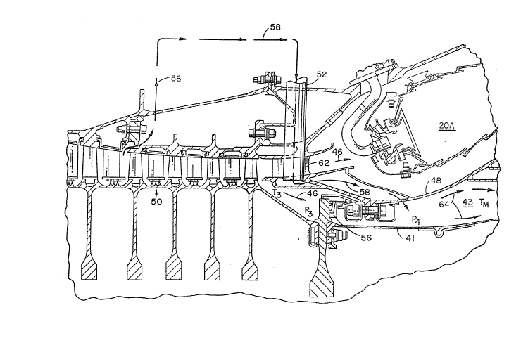
In FIG. 3, a simpli~ied schematic illustratiDn of
the cooling sy~tem of the present inv~ntion dsp~cts
cooling air extraction from am axially forward stage
~0 of multi-stage compres~or 50 through a conduit 5~
Conduit 52 channels air from the forward stage of
multi-stage compressor 50 to the cavity 43.
Pre~erably, the improved engine coolin~ syste~ o~
the present invention (FIG. 3), replac~ the labyrinth
1~ seal of FIG. 2 with the improved gas bearing seal ~6.
Alternati~ely, a low ~eakag0 labyrinth seal may b~
: used or other type o~ sealing device which
significantly reduces CDP leak~ge. The pre~sure P3 on
the upstream side of ~he gas bearing ~eal 56 is, of
~our~e, greater than the pressure P4 located in cavi~y
43 on the down~tream side of the seal 56. The
improved gas bearing seal 56, is b~lieved to reduce
~ leakage by up to 80% and reduce temperature rise o~
; l~akage by up to 90% over the labyrinth seal 42 when
used in comm~rcial aircra~t gas turbine engines.
As a result of reduced lea~age resulting ~rom ths
: improved gas b2aring seal 569 ano~her sour~e of air i~
nee~ed ~or purge flow to cool the temperatur~ of the
cavity 43. This additio~al purge ~low is provided ~y
the axially forward stage o~ csmpres~or 50. The
~ extracted intermed~a~e ~ta~e air 58 having a
: temperature T; i~ directed through conduit 52, conduit
52 extending ~rom th~ for~ard ~tage ~hrough ~trut 62
~ . .
':
,, ~.
.
~$~ ~3
13 13DV-10766
and into cavity 43. The axially forward stage
corresponds to the sixth or seventh stage of a
compressor in a type CFM-56 engirle, or stages 8 to ll
in a typ~ CF-6 engine.
The air in cavity 43 indicated by arrows 64 (FIG.
3 ) is a mixtura of the intermediate stage air 58 and
a smal 1 s~uantity o~ CD air 4 6 . P.pproximately 8 0% o~
the air in the cavity 4 3 originates Prom the
inter~ediate ~tage with th~ remainder originatin~ ~rom
the CD ai~ 46 which leaks tlhrough the improved gas
bearing seal 56.
An advantage o~ u~ing the intermediate stage air
58 for cooling is 1:hat the intermediate stage air i~
much "cheaper~' than CD air because less work has been
performed sm the intermediate ~tage air by the
compressor. Furthermore, since the intermes91iate stage
air 58 is much cooler than the CD air 46 (Tj<<T3), less
f low is regui:red .
As a result of the c:ooling ~ystem of the present
invention, the c:avlty ~low temperature T9" which is a
mixture of the CDP seal leaka~ alr (CD air 46) and
the purge flow air (intermediate stag~ air 58~, is
~ ower than the temperature TD ~ FIGo 2~ L~wer
temperature offers more effective cooling and ree;ults
in less mass flow beinS7 re~uired. Tn addiltion, the
major portion o~ the mass flow fs:~r the improved engine
cooling ~yste~ of the pre~ent invention consist~i of
cheaper intermedi~te 6tage compr~sor air~ Thus9 fllel
consumption is improved, ~etal temperature~ reduced
and turbine life increased.
The ~oregoing detail2d description is intended to
be illu~strativ~ and non-li~itil g. ~qany c:han~e~ and
modi~ at:Lc~ns are po:3sibl~3 1n light o~ ~a above
2~ 2~
14 13DV-107S6
teachings. Thus, it is understood that the invention
may be practiced otherwise than a~ specifically
descxibed herein andl stlll be within the scope ~ the
appended claims .