Note: Descriptions are shown in the official language in which they were submitted.
207621 3
DI8C~P~ ELECTRODE 8TABILIZER
Background Of The Invention
The invention relates to electrostatic precipitators
and in particular to a frame for stabilizing discharge
electrode elements in an electrostatic precipitator.
Electrostatic precipitators are used to remove
particulate from an exhaust gas stream. Such precipitators
generally include a plurality of parallel discharge electrode
elements alternating with a plurality of grounded collecting
electrode plates. The discharge electrode elements comprise
formed sheet metal configurations vertically hung in the
direction of gas flow. The grounded collector plates comprise
formed sheet metal plates spaced from and aligned parallel to
the electrode discharge elements. The grounded collecting
electrode plates are generally mounted and stabilized directly
from the precipitator casing or housing.
When a particulate laden gas flows through the spaces
between the discharge electrode elements and the grounded
collector plates, particulate in the gas take on a charge from
the electric corona discharge emanating from the discharge
elements. The charged particles are subsequently attracted to
the grounded collecting electrode plates. By this mechanism,
particulate are removed from the exhaust gas flowing through
the precipitator. In conventional precipitators, the collector
plates are tapped with a rapping device so as to force the
collected particulate down the collecting plate and into a
collection chamber.
207~i21~
- One currently utilized electrostatic precipitator
design is shown in Figure 1. The precipitator includes a
casing or housing 10 that encloses a plurality of electrically
charged sheet metal elements 12 interspaced with alternating
grounded collector plates 14. Particulate laden air 13 enters
the front of the precipitator casing 10 and passes through the
spaces between discharge electrode elements 12 and collector
plates 14 so as to remove particulate. Clean air 15 then exits
through an opening in back of the precipitator housing.
Discharge electrode elements 12 are suspended from
a support frame 16, which includes first frame members 16a
extending parallel to the longitudinal dimension of the housing
and second frame members 16b extending perpendicular to the
first frame members 16a and connected therebetween. The
support frame 16 is suspended from electrically insulated
supports 18 mounted on the top of housing 10 and connected to
frame members 16b. The top of each electrode element 12 is
connected to the spaced frame members 16a. A steadying
frame 20 engages the bottom of each discharge electrode element
12 so as to reduce swaying of the electrode plates. The
connection of the plates 14 to the casing 10 is not illustrated
for purposes of clarity. However, the grounded collector
plates 14 are mounted directly on the casing 10 via hanger
bolts and anvil beams to form a fixed connection with the
housing end girders.
When the discharge electrode elements 12 of the
electrostatic precipitator shown in Figure 1 are charged, they
are attracted to the grounded collector plates 14. This
2~7621~
attraction often results in regular swaying of the discharge
electrode elements. Such swaying is a problem because it
changes the distance between the discharge electrode elements
and collector plates so as to reduce the efficiency of the
electrostatic precipitator. In some instances, regular
harmonic swaying occurs in which circumstances the amount of
sway may be so great as to bring discharge electrode
elements 12 into contact with some of the collector plates 14.
Such contact damages the precipitator unit. The steadying
frame 20 is used to reduce sway of the electrode plates 12.
However, steadying frame 20 does not eliminate sway altogether.
To overcome the sway problem, conventional
electrostatic precipitators have utilized a spacer steadying
bar 22 installed between a discharge electrode plate and a
collector plate. Figure 2 is a cross sectional view of the
precipitator shown in Figure 1 looking in the direction of gas
flow. As shown in Figure 2, a number of spacer steadying
bars 22 are fixed between the steadying frame 20 and a
collector plate 14. Such spacer steadying bars are made of an
electric insulating material in order to prevent flow of
electric current from the discharge electrode elements to the
collector plate. The spacer steadying bar 22 prevents the
discharge electrode elements from swaying because all of the
electrode elements sway only in unison due to the
interconnection of steadying frame 20.
When spacer steadying bars are used to reduce swaying
of discharge electrodes, particulate stick to the surface of
the spacer steadying bars. This particulate build up causes
207621 ~
- electric current channels to form between the discharge
electrode elements and the collecting plate through the
particulate coating on the surface of the spacer steadying
bars. The surface currents result in spacer steadying bar
degradation and eventual breakdown of the spacer steadying bar.
When such breakdown occurs, time consuming electrostatic
precipitator repairs are required forcing the shut down of the
equipment whose exhaust gas is being cleaned by the
precipitator.
Summary Of The Invention
Accordingly, the invention is directed to providing
an electrostatic precipitator in which discharge electrode sway
is prevented by a stabilizer system that is less prone to
regular mechanical breakdowns. The invention also provides a
frame that stabilizes discharge electrode elements of an
electrostatic precipitator without attachments between the
electrode elements and the grounded collector plates of the
precipitator or the precipitator's grounded housing structure.
Furthermore, the invention provides a discharge electrode
stabilizer system that can be fitted on both existing and new
electrostatic precipitators without great expense.
More specifically, the invention provides an
electronic air cleaner for removing particulate materials from
a gas stream flowing through its housing that includes a
plurality of aligned electrically chargeable electrode elements
suspended from the housing. At least one grounded collector
plate is fixedly supported by the housing and aligned between
207fi21 9
- two of the plurality of electrode elements in a position spaced
from the two electrode elements to form a clearance
therebetween. The collector plate has an opening and an
electrode stabilizer extends between the two of the plurality
of the electrode elements. The stabilizer passes through the
opening in the collector plate without touching the collector
plate. The stabilizer and the two electrode elements are
configured to form a rigid stabilizing system or structure
substantially eliminating sway between the electrode elements
and the collector plates.
Brief Description Of The Drawings
Figure 1 is a partial perspective view of a
conventional electrostatic precipitator.
Figure 2 is a cross-sectional view of the
electrostatic precipitator of Fig. 1 looking in the direction
of gas flow.
Figure 3 is a cross-sectional view of an
electrostatic precipitator constructed according to the
principles of the invention looking in the direction of gas
flow.
Figure 4 is a detailed cross-sectional view of one
of the stabilizer frames of the invention shown in Figure 3.
Detailed Description
Reference will now be made in detail to the
embodiment of the invention illustrated in the accompanying
2076~l9
- drawings. Throughout the drawings, like reference characters
are used to designate like elements.
A cross-sectional view of an electronic air cleaner
constructed according to the principles of the invention is
illustrated in Fig. 3. Fig. 3 shows a cross-sectional view of
an electrostatic precipitator looking in the direction of air
flow. According to the illustrated embodiment, the
electrostatic precipitator of the invention includes a
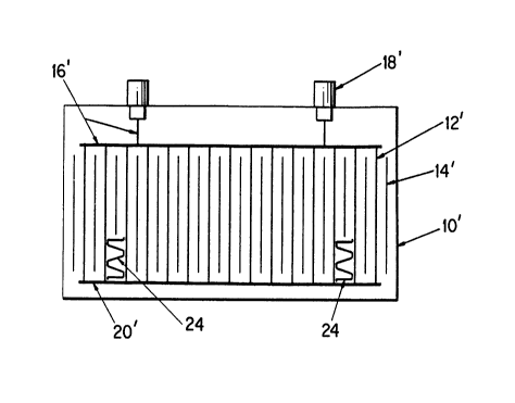
casing 10' in which a plurality of electrode discharge
elements 12' and a plurality of grounded collector plates 14'
are housed. Discharge electrode elements 12' are suspended
from a support frame 16', which in turn is suspended from
electrically insulated supports 18' mounted on the top of
housing 10' in the manner previously mentioned in connection
with the discussion of Figures 1-2. The grounded collector
plates 14' are fixedly mounted on housing 10' by hanger bolts
and anvil beams supported on the housing end girders, also in
the manner previously discussed in connection with Figures 1-2.
The electrode stabilizer system of the invention
preferably comprises a rigid stabilizer frame 24 affixed only
to two of the plurality of electrode elements. Alternatively,
frame 24 could be connected to more than two of the discharge
electrodes. Rigid stabilizer frame 24 and the two adjacent
discharge electrodes 12' to which the stabilizer frame is
affixed form a rigid structure that substantially eliminates
sway between the electrode elements and the interspaced
collector plate. Preferably, stabilizer frame 24 is made of
the same electrically conducting material as the electrode
207~
- discharge elements 12'. As embodied herein, both the electrode
elements 12' and the rigid stabilizer 24 are made of metal.
Stabilizer 24 may be affixed to electrode elements 12' by any
known method, including welding the stabilizer frame to the
electrode elements.
The electrode stabilizer frame passes through an
opening in one of the collector plates 14' such that the
stabilizer frame connects two adjoining electrode elements
without touching collector plate 14' therebetween.
Alternatively, the term "opening" as used herein includes the
design of the collector plate 14' shown in Fig. 3, which is
shorter than the other collector plates to permit the frame 24
to pass underneath the plate 14' and above steadying frame 20'.
Figure 4 shows stabilizer frame 24 passing through an
indentation or hole 13 in collector plate 14'.
Stabilizer frame 24 preferably comprises a plurality
of cross members each affixed to two discharge electrode plates
in a configuration that forms a non-deformable shape in
conjunction with the two electrode plates and permits air to
flow therethrough. One of the stabilizer frames 24 of the
electrostatic precipitator shown in Fig. 3 is shown in greater
detail in Fig. 4. The stabilizer frame is preferably comprised
of a bent metal rod or strip affixed to adjoining electrode
discharge elements 12'. As discussed above, the frame is
attached to the electrode plates by welding or other known
attachment methods and may be connected directly to
electrodes 12', which may include an intermediate conducting
plate 11 disposed between the electrodes and the frame.
2Q7~i21 9
~- Frame 24 is configured in a manner to form with the
electrodes 12' one or more generally triangular shapes having
hollow spaces 25' through which air can flow. The triangular
shape is beneficial because it forms a rigid and non-deformable
truss-type member.
As can be seen in Fig. 3, collector plates 14'
generally extend vertically from a point just below discharge
electrode support frame 16' to a point just above discharge
electrode steadying frame 20'. Collector plates 14' are
aligned substantially parallel to electrode elements 12. The
particulate-laden exhaust gas passes through the clearance left
between discharge electrode elements 12' and collector
plates 14', which is at least as large as the required
electrical clearance.
As shown in Fig. 3, for example, just a few
stabilizer frames can stabilize a large number of discharge
electrode elements in an electrostatic precipitator. This
stabilization is achieved because each of the electrode
elements is connected at its top to support frame 16' and at
its bottom to steadying frame 20'. Accordingly, when
stabilizer frame 24 substantially eliminates sway between the
two discharge electrodes 12' to which the frame is affixed and
the interspaced collector electrode, sway of the other
discharge electrodes 12' is also substantially eliminated
through steadying frame 20'.