Note: Descriptions are shown in the official language in which they were submitted.
2 0 7 S 2 3 ~
ENGINE AND TRANSAXL~ MODULE
Background of the Invention
1. Field of the Invention:
The invention relates to mechanisms for coupling an
engine and tr~n~le to a vehicle frame.
2. Description of the Related Art:
Conventional powered vehicles such as lawn and garden
tractors provide a power source or engine, and a transaxle
that transmits rotational motion from the engine to ground
engaging driven wheels. When the transaxle transmits torque
to the driven wheels to drive the vehicle forward, an equal
and opposite torque load is transmitted to the frame of the
vehicle. For example, the transaxles of rear wheel drive
vehicles will urge the vehicle frame to rotate upwardly and
rearwardly about the rear wheels in response to the vehicle
being driven forwardly. A relatively large torque load is
thereby transferred to the vehicle frame at the point where
the transaxle is coupled to the frame. The vehicle is
typically prevented from rotating upwardly and rearwardly by
the weight of the vehicle itself. Vehicle frame structures
must be strong enough to withstand the large concentrated
loads that result from driving torque being applied to the
driven wheels. Conventional vehicle frames must also be
sufficiently strong to carry the weight of vehicle components
such as the engine. Many conventional vehicle frames are
manufactured from relatively rigid and strong metal materials
such as steel, and therefore easily absorb large concentrated
force loads associated with driving torque and engine weight.
However, because conventional frame structures must be
relatively strong, they are relatively expensive to
manufacture and assemble.
A first type of conventional lawn and garden vehicle
provides an engine and transaxle that are each separately
attached or coupled to the frame. Because the two components
are separately carried by the frame, interchangeability of
components is possible. Therefore, different sizes of
engines, or different types of trAnc~les can be installed on
~'
207~2~I
identical frames during manufacture. However, removal of the
engine or transaxle for servicing is relatively difficult
since the two parts must be disconnected from each other to
allow removal of either component from the vehicle.
Conventional vehicles often provide a series of belts and
pulleys between the engine and transaxle that must be
disconnected for removal of either the engine or the
transaxle. Many engine or transaxle service operations would
not otherwise require the two components to be uncoupled from
each other, and therefore the process of disconnecting the
components from one another is often unnecessary and
needlessly time consuming other then to allow removal from the
vehicle. This type of conventional vehicle transfers
relatively large forces to the frame as a result of driving
torque, and may transfer a large portion of the weight of the
engine directly to the frame. Therefore strong materials such
as steel that can withstand relatively large concentrated
loads are typically utilized to manufacture the vehicle frame.
A second type of vehicle provides a unitized engine and
transaxle. Vehicles of this type provide engines and
transaxles that are integral with each other or unitized, and
therefore can be removed from the vehicle without being
uncoupled from each other. However, since they are formed
integral with each other, interchangeability of components is
eliminated. Some of the vehicles of this type position the
engines's center of gravity directly over the axle such that
the weight of the engine is largely transferred to the axle
and wheels rather than to the frame. Therefore the force
corresponding to the weight of the engine that is applied to
the frame is reduced. However, the concentrated load applied
to the frame that results from driving torque being
transmitted to the wheels typically remains relatively large,
and the frame must therefore be manufactured from a relatively
strong material to withstand high concentrated loads.
The two types of vehicles discussed above therefore
require the use of a frame that can withstand large
concentrated loads due to the torque associated with driving
~'
2076231
the vehicle. Conventional vehicles may also require the
vehicle frame to withstand relatively large concentrated loads
associated with the weight of the engine. The vehicles
discussed above are therefore particularly unsuitable for use
with a light-weight frame structure made of an inexpensive
material such as plastic that may not be capable of
withstanding high concentrated loads.
It would therefore be desirable to provide a mounting
mechanism that transfers relatively small concentrated loads
to the frame that result from acceleration of the vehicle.
Such a mounting mechanism would allow the vehicle frame
structure to be manufactured from relatively inexpensive
materials such as plastic. It would also be desirable for
such a mechanism to allow the engine to be positioned such
that the center of gravity of the engine is vertically aligned
with the axle to thereby transfer its weight downwardly to the
ground through the axle and ground engaging wheel, rather than
through the frame. It would be desirable to provide a
mechanism that mounts an engine and transaxle to a frame and
that allows interchangeability of components. It would be
desirable to provide a mounting mechanism that also increases
the ease with which the components can be removed from the
vehicle for service, and that allows the engine and transaxle
to be removed without requiring the two components be
disconnected from one another for removal.
Summary of the Invention
The preferred embodiment of the present invention
provides a mechanism for mounting an engine and transaxle to a
vehicle frame. The engine, transaxle, and belt arrangement
that couples the engine with the transaxle are all carried by
a horizontally extending plate-like member. The member
extends longitudinally a substantial distance and is coupled
to the vehicle via first and second coupling means. The
second coupling means is longitudinally offset from the first
coupling means such that the member acts as a lever arm for
transmitting torque loads to the frame. Since the second
coupling means is longitudinally spaced a substantial distance
2076231
from the first coupling means, the concentrated load imparted
to the frame due to driving torque in the transaxle is
relatively small. Therefore, the frame member can be
manufactured from a material such as plastic that may not be
capable of withstanding high concentrated loads. The engine
is carried by the member such that the engine's center of
gravity is positioned in general vertical alignment with the
axle, such that a large portion of the weight of the engine is
transferred to the ground via the rear wheels, rather than to
the vehicle frame. The member can be removed from the vehicle
frame without disconnecting the engine from the transaxle,
such that the removal process is facilitated. The engine and
transaxle can be removed from the rest of the vehicle as a
single unit or module. The member must be unbolted from the
frame, and the vehicle lifted and walked forwardly from the
module. The frame is a relatively light material, such that
the removal of the frame from the module can readily be
accomplished. Access is thereby provided for servicing the
engine or transaxle.
Brief DescriPtion of the Drawings
Figure 1 illustrates a vehicle with which the preferred
embodiment of the present invention may be used.
Figure 2 is a side view of the preferred embodiment fully
assembled.
Figure 3 is an exploded perspective view of the vehicle,
plate member and transaxle according to the preferred
embodiment with the engine not shown.
Figure 4 is a plan view of the present invention.
Figure 5 is a sectional exploded view from the rear of
the preferred embodiment.
Figure 6 illustrates the coupling between the vehicle
frame, transaxle, and plate member.
Description of the Preferred Embodiment
Referring now to Figure 1, there is shown a vehicle 10
with which the preferred embodiment of the present invention
may be used. The vehicle 10 is provided with a frame 12
20762~1
manufactured from a plastic or composite material. Ground
engaging front wheels 14 support and steer the vehicle 10, and
rear driven wheels 16 act to propel the vehicle 10 forwardly
or rearwardly.
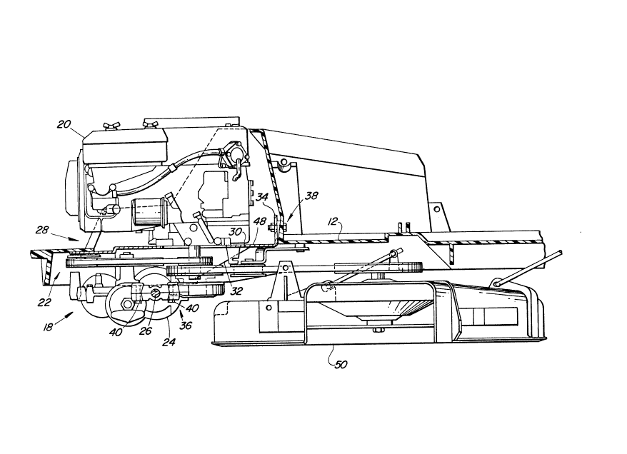
A drive mechanism 18, as best seen in Figure 2, is
provided by the preferred embodiment of the present invention
for supplying power to the driven wheels 16. A power source
or engine 20 is carried at the rear of the vehicle 10. A belt
and pulley arrangement 22 operatively connects the engine 20
with a transaxle 24. The transaxle 24 contains gears and/or a
hydrostatic drive, a diff~rential, and an axle 26 for
transmitting rotational power from the engine 20 to the driven
wheels 16.
A mounting mechanism 28, as seen in Figures 2 - 5, is
also provided according to the preferred embodiment for
coupling or mounting the drive mechanism 18 to the vehicle
frame 12. A generally horizontally disposed plate-like member
30 is provided for mounting the engine 20, transaxle 24, and
pulley arrangement 22 to the vehicle frame 12. The member 30
includes first and second bent or angled portions 32 and 34,
that act to stiffen and strengthen the member 30. The member
30 is coupled with the frame 12 via first and second coupling
means 36 and 38. The first coupling means 36 includes two
pair of bolts 40 that are located along the outer edge
portions of the frame 12 near the axle 26. The first coupling
means 36 couples the first angled portions 32 of the member 30
with the vehicle frame 12. The second coupling means 38
couples the second angled portion 34 of the member 30 with the
vehicle frame 12 near the centerline of the vehicle 10. The
engine 20 is bolted to the plate member 30 at a plurality of
locations 42, best seen in Figure 3. The transaxle 24 is
coupled to the plate member 30 via the bolts 40 of the first
coupling means 36. A rear attachment bolt 43 is also provided
that couples the transaxle to the plate and transmits torque
loads from the transaxle 24 to the plate member 30. The rear
attachment bolt 43 also acts to pivotally carry a clutch arm
44 that can be operatively pivoted during operation to release
A
2076231
driving tension in the belt 46. Figure 3 illustrates the
vehicle frame 12 with the plate member 30, engine 20 and
transaxle 24 removed. The frame 12 defines a generally open
compartment 47 as best seen in Figures 3, 4, and 5 within
which the engine 20, transaxle 24 and plate member 30 are
situated during operation.
Figure 6 illustrates the first coupling means 36. The
bolts 40 couple the transaxle 24 to the plate member 30, and
also act to secure the plate member 30 against the frame 12.
A nut 52 threaded onto each bolt 40 presses an abutment member
54 against the frame 12. 'A spacer member 56 is also threaded
onto each bolt 40. The spacer 56 acts to limit the degree to
which the frame 12 can be compressed. The frame material
being compressed is therefore prevented from being squeezed
out from between the plate member 30 and the abutment member
54. The frame structure thereby provides a firm structure to
which the plate member 30 can be mounted. The spacer 56 also
acts to couple the plate member 30 to the transaxle 24 such
that the transaxle 24 remains securely fixed with the plate
member 30 when the frame 12 is removed. The abutment members
54 act to spread force loads and thereby decrease the
concentrated loads transferred from the transaxle 24 and plate
member 30 to the vehicle frame 12.
Next, the operation of the preferred embodiment of the
present invention will be discussed. During normal operation,
the engine 20 is carried by the plate member 30 in such a
position that the engine's center of gravity is positioned
generally directly above the axle 26. The vertical alignment
of the engine's center of gravity with the axle 26 acts to
transfer the weight of the engine 20 downwardly to the ground
via the plate member 30, transaxle 24, axle 26 and ground
engaging wheel 16. If the engine's center of gravity were
horizontally offset from the axle 26, the engine 20 would tend
to pivot about the axle 26 under the force of its own weight.
This pivoting tendency would place a load on the frame 12
associated with the weight of the engine 20, such that the
frame 12 would have to be relatively strong to withstand the
207~31
engine weight loading. By positioning the center of gravity
of the engine 20 generally directly above the axle 26, the
weight of the engine 20 is generally not borne by the frame
12, but rather is transferred to the ground via the plate
member 30, transaxle 24 and rear ground engaging wheels 16.
Since concentrated loads on the frame 12 resulting from the
weight of the engine 20 are reduced or eliminated by the
preferred embodiment, a relatively inexpensive frame structure
that may not be capable of withstanding high concentrated
loads corresponding to engine weight can therefore be
employed.
Vehicle frames must also withstand another type of force
loading. When the vehicle 10 accelerates forwardly, the
engine 20 transmits rotational power to the transaxle 24,
which then transfers the rotation to the driven wheels 16. As
the rotational force is being applied to the wheel 16, an
equal and opposite force is being applied to the vehicle 10.
If the vehicle 10 accelerates forwardly, for example, the
torque load on the vehicle 10 will urge the vehicle 10 to
pivot upwardly and rearwardly about the axle 26. If the
vehicle 10 accelerates rearwardly, the torque load on the
vehicle 10 will urge the vehicle 10 to pivot downwardly about
the rear axle 26. The equal and opposite torque load or
twisting load will be transferred to the frame 12 through the
mechanism 28 that couples the transaxle 24 to the vehicle
frame 12.
The transaxle 24 according to the preferred embodiment is
coupled to the plate member 30, and therefore the torque load
created at the transaxle 24 that must be absorbed by the
vehicle 10 is first transferred to the plate member 30. The
plate member 30 is thereby urged to pivot about the axle 26.
When accelerating forwardly for example, the plate member 30
will be urged to pivot upwardly about the axle 26, such that
the second angled portion 34 located at the front of the plate
member 30 is forced upwardly. Therefore, the second coupling
means 38 will be urged to pivot upwardly and rearwardly about
the axle 26, and will therefore exert a force on the frame 12
20762~1
to pivot upwardly at this location. The portion of the frame
12 to which the second coupling means 38 is attached must
therefore be sufficiently strong to withstand this
concentrated load, or else the frame 12 will break or tear
away from the plate member 30.
However, the present invention according to the preferred
embodiment employs a lever principle to reduce the amount of
force transferred from the plate member 30 to the frame 12.
The lever principle teaches that a torque force having a given
magnitude may be applied to a body by the application of a
force at a distance from a pivot axis. A torque force having
the same magnitude can be created by applying a smaller amount
of force at a greater distance from the pivot axis. The
second coupling means 38 according to the preferred embodiment
is located a distance forwardly from the axle 26 about which
the plate member 30 is urged to pivot, such that a lever arm
48 is created. Since the frame 12 is holding the plate member
30 from pivoting at a location longitudinally extended from
the plate member's axis of rotation, i.e. from the axle 26,
the force required to prevent pivoting is relatively small.
In other words, since the lever arm 48 created by the plate
member 30 extends a substantial distance from the plate
member's axis of rotation, i.e. the rear driven axle 26, the
force being transferred through the second coupling means 38
from the plate member 30 to the frame 12 is relatively small.
The farther the plate member 30 extends forwardly, the smaller
will be the concentrated load transferred from the plate
member 30 to the frame 12 through the second coupling means
38. The lever arm 48 established by the preferred embodiment
of the present invention therefore reduces the concentrated
load transferred to the frame 12 that results from driving
torque being applied to the wheels 16. The preferred
embodiment thereby allows the use of a frame 12 manufactured
from a relatively inexpensive material such as plastic that
may not be capable of withstanding relatively large and
concentrated force loads.
207~
The rear portion of the plate member 30 is adapted to
carry a container (not shown) that would catch grass cut by a
mower 50. The grass container would be mounted to the plate
member 30 to transfer the weight of the container and its
contents to the plate member 30. The weight of the container
is therefore generally transmitted through the plate member 30
and transaxle 24 to the ground engaging wheels 16, rather than
directly to the vehicle frame 12. Relatively large
concentrated loads associated with the use of a grass
container would therefore be transmitted first to the plate
member 30, and then to the frame 12 via the first and second
coupling means 36 and 38. The frame 12 can therefore be
manufactured from a material such as plastic that may not be
capable of withstanding large concentrated loads that would
result from mounting a container to the vehicle frame 12.
According to the preferred embodiment, the engine 20,
transaxle 24, and the belt arrangement 22 extending
therebetween are all coupled with the plate member 30 during
operation. The plate member 30 therefore acts as the means
for coupling the engine 20, transaxle 24 and belt arrangement
22 with the vehicle frame 12. The three components 20, 22,
and 24, and the plate member 30 that carries them therefore
act as a module that can be removed as a single unit to
service any of the components 20, 22 and 24. To remove the
module from the vehicle 10 for service, the plate member 30
must be unbolted from the frame 12. Linkages (not shown)
extending between the module and the controls at the front of
the vehicle 10 must be uncoupled and removed. The fuel line,
electrical lines, throttle cable and muffler are then
uncoupled from the module. The frame 12 can then be lifted
upwardly and shifted forwardly from the module. The frame 12
is made of a light-weight plastic material such that the rear
of the frame 12 can easily be lifted from the module and
walked forwardly to expose the module components 20, 22 and 24
for service. The three components 20, 22 and 24 are not
required to be uncoupled from each other during the process of
removal, thereby increasing the ease with which access can be
2Q7~
gained to the various components. Since the components remain
operatively linked after removal, the components can be
operated and tested before re-attaching the components to the
vehicle frame 12. To reattach the module to the frame 12, the
frame 12 is wheeled rearwardly over the module, and lowered
onto the first angled portions 32 of the plate member 30. The
plate member 30 can then be bolted to the frame 12 at the
first and second angled portions 32 and 34.
Similarly, the transaxle 24, engine 20 and module plate
30 can be sub-assembled off-line during the process of
manufacture and therefore can be separately tested before
being attached to the vehicle frame 12.
The engine 20 and transaxle 24 are each coupled to the
plate member 30, and are connected by the belt arrangement 22
that extends therebetween. A variety of different types and
sizes of engines and transaxles can be coupled with the plate
member 30 without requiring modification to the frame 12.
Since frames having identical design can accommodate a
plurality of different engines and transaxles, an entire line
of tractors can be manufactured using the same frame design.
The cost of tooling and manufacturing a variety of different
frame designs that would accommodate various sizes and types
of components is therefore eliminated.
The preferred embodiment of the present invention
provides optional rear attachment points 58 formed in the
plate member 30. The rear portion of the frame 12 can be
bolted to the plate member 30 at the optional attachment
points 58 to add rigidity to the rear of the frame 12. When
the frame 12 is fixed or bolted to the plate member 30 at the
optional attachment points, a portion of the torque load
created by the transaxle 24 will be transmitted from the plate
member 30 to the rear portion of the frame 12 via the optional
attachment points 58. However, since the rear portion of the
frame 12 will tend to flex, it will absorb only a relatively
small portion of the torque load, and the majority of the
torque load will be transferred to the frame 12 via the second
coupling means 38.