Note: Descriptions are shown in the official language in which they were submitted.
-1- 2076334
AM~ T-F~ PRO~ SING SY51~:~
Technical Fiel~
This invention relates to providing an
ambient air-free atmosphere within processing
vessels, in particular within processing vessels
used in the manufacture of semiconductor devices.
Background
Many of the manufacturing steps used to
make semiconductor devices and integrated circuits
require that a very high purity gaseous atmosphere
be maintained within the vessel used for
processing. Solid particles and vapor phase
contaminants, notably moisture and o~ygen, must be
kept to an absolute minimum. Since these
contaminants are contained in air, air infiltration
into the vessel must be minimized.
Among the processes strongly affected by
these contaminants is the annealing of
titanium-coated silicon wafers in a nitrogen or
argon environment to promote the formation of
titanium silicide. As little as 1 to 5 ppm of
o~ygen and moisture can lead to the formation of
undesirable titanium o~ide. Similarly, the
deposition of polysilicon onto esposed silicon on
wafers to form bipolar emitter structures is very
sensitive to o~idation of the e~posed silicon. If
air is initially present in the low pressure
processing vessel, an o~ide will form on the exposed
silicon surfaces which can degrade device
performance.
D-16559
207633~
--2--
The estent of air infiltration into process
vessels, the forces governing this phenomenon and
the problems it can cause are not fully recognized
in the integrated circuit industry. Most commercial
semiconductor equipment is operated in batch or
semibatch fashion. A load of one or more wafers is
placed into a vessel, processed and unloaded.
Measurements of the purity of the atmosphere within
a wide variety of processing vessels during all
phases of their operation reveal that typically
considerable infiltration of room air into a
processing vessel occurs during loading and
unloading, which leads to detrimental contamination.
A processing vessel usually must be
maintained at elevated temperature at all times
because of the long times required for cooling and
heating. The primary force for the influ~ of air
into the vessel is the buoyancy difference between
cool room air and the hot gases in the vessel. Hot
gases in the vessel tend to rise toward the top of
the vessel; cool room air flows in and down toward
the bottom of the vessel through any openings in the
vessel. Thus when a vessel is opened to admit or
remove a workpiece, a large influx of room air
occurs, and the atmosphere in the vessel becomes
seriously contaminated.
In commercial practice, wafers are often
placed in a boat on an open, motorized cantilevered
carrier. When the processing vessel is opened, the
carrier is transported into the processing vessel.
As the wafers approach the processing vessel, the
wafers are heated by radiant and convective heat
transfer from the processing vessel. At this point,
D-16559
- 207633A
-3-
the wafers are still in a room air environment which
is often deleterious to them as their temperature
rises. Then, as wafers enter the processing vessel,
they are e~posed to still higher temperatures and to
large concentrations of oxygen, moisture and
particles which entered when the processing vessel
was open.
Once the vessel is closed, the process
gases begin to purge the airborne contaminants from
the vessel. However, purging to levels below 100
ppm can take tens of minutes. As a result, process
time is lost, equipment throughput decreases and
capital costs per wafer processed increase.
The purging problem is even more severe for
a low pressure or evacuated vessel. Here, moisture
from infiltrating air adsorbs on the inner surface
of the vessel and all other exposed components. Its
removal under vacuum is difficult and slow.
Summary of the Invention
An object of the present invention is to
provide an improved apparatus and method for
creating an ambient free atmosphere of selected gas
in a processing vessel and a workpiece preparation
vessel.
Another object is to provide an improved
apparatus and method for processing semiconductor
and integrated circuit components in an atmosphere
of highly reduced ambient air concentration.
It is a feature of this invention to use a
laminar fluid curtain flow to provide an atmosphere
of selected gas within a vessel and to repress the
infiltration of ambient air.
D-16559
_4_ 2076334
Advantages are that the invention provides
an atmosphere of selected gas with reduced ambient
air concentration within a reduced time comparea to
prior methods and apparatus.
The above objects, features and advantages
are achieved by this invention in a system for
processing a workpiece in a selected atmosphere,
wherein the system comprises a processing vessel
having an opening for entry of the workpiece, and a
diffuser with an emitting surface oriented to emit a
laminar curtain flow of selected gas across the
processing vessel opening. The system further
comprises a preparation vessel having an opening
congruent with the processing vessel opening and a
diffuser with an emitting surface oriented to emit a
laminar curtain flow of selected gas across the
preparation vessel opening. Included are means for
bringing the preparation vessel opening and the
processing vessel opening into coincidence and means
for transferring the workpiece from the preparation
vessel into the processing vessel when the
preparation vessel opening and the processing vessel
opening are in coincidence.
The means for transferring the workpiece
comprises a carrier or boat which is loaded in the
normal air atmosphere with the workpiece, and then
transported into the preparation vessel which is at
atmospheric temperature. Selected gas flow is then
started from the diffuser at the opening of the
preparation vessel thereby purging the preparation
vessel of air. Thus air contacting the surfaces of
the work is replaced with selected gas while the
work is still at atmospheric temperature. Air is
D-16559
-5- 2076334
similarly purged from the processing vessel by
selected gas emanating from the diffuser at the
opening to the processing vessel. Upon bringing the
openings of the preparation vessel and processing
vessel into coincidence, the work is transferred
into the processing vessel without a detrimental
influx of atmospheric air into the system.
In another embodiment, the system comprises
a processing vessel having an opening for entry of
the workpiece, and a diffuser located within the
processing vessel remote from the opening. The
diffuser has an emitting surface oriented to
discharge a laminar flow of a selected gas at a
location intended for the workpiece during
processing. The system further comprises a
workpiece carrier or boat for retaining and carrying
the workpiece into the workpiece opening in the
processing vessel and means for supporting and
transporting the carrier into the processing vessel.
A variant of this embodiment further
comprises a trailing diffuser mounted on the carrier
end intended to trail during entry of the carrier
into the processing vessel. The diffuser is
oriented to discharge away from the workpiece, has
an emitting surface for issuing a laminar flow of
selected gas, and is sized to fit within the
processing vessel. This variant provides greater
protection against the infiltration of air into the
processing vessel.
In yet another embodiment, the carrier has
a leading diffuser oriented to discharge at the
intended workpiece location and a trailing diffuser
oriented to discharge away from the intended
D-165S9
-6- 2 07 633g
workpiece location. The carrier, the diffusers and
the work are sized to fit within a processing
vessel. The selected gas flow from the diffusers--
purges the surfaces of the work before
transportation of the work into the processing
vessel, and maintains an atmosphere of selected gas
within the processing vessel upon transportation
into the vessel.
RRIEF D~.~CRIPTION OF THE DRAWINGS
Figs. lA through lE are vertical sectional
views showing an embodiment of the apparatus
comprising the invention during various stages of
operation.
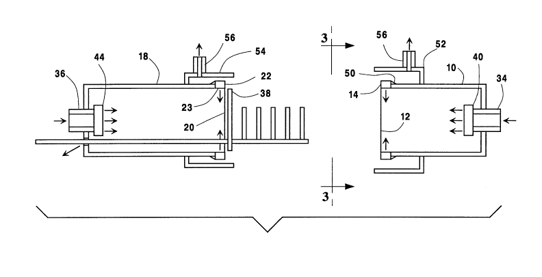
Fig. 2 is a vertical sectional view of a
variant of the embodiment shown in Fig. 1.
Fig. 3 is an end view of the apparatus in
Fig. 2 taken in a direction of the arrows labeled
3-3.
Fig. 4 is also an end view of a variant of
the apparatus in Fig. 2 taken in the direction
indicated by arrows 3-3, and showing a variation of
the diffuser configuration which may be employed in
this invention.
Fig. 5 and Fig. 6 are vertical sectional
views of other embodiments of the invention.
Fig. 7 and Fig 8 are vertical sectional
views of other embodiments of the invention wherein
the normally separable components of the apparatus
are shown separated.
D-16559
2076334
--7--
D~TAIT~n D~SCRIPTION OF T~ INV~TION
Turning now to the drawings, depicted in
Fig. lA through Fig. lE is an embodiment of a novel
apparatus for processing of a workpiece in a
selected atmosphere. In Fig. lA is shown a
processing vessel 10 having an opening 12 for a
workpiece. Adjacent to the opening is a diffuser 14
with an emitting surface 16 oriented to emit a
laminar curtain flow of selected gas across the
process vessel opening 12. The diffuser gas enters
the processing vessel through the opening, purges
the vessel of atmospheric air and prevents
atmospheric air from entering, thereby providing an
atmosphere of selected gas within the processing
vessel. A selected gas may be an inert gas or a
process or reactant gas or mi~tures thereof.
A common processing vessel to which this
invention is particularly suited is a furnace tube.
A vessel opening may also be provided with a closure
so that the vessel may be operated under pressure or
under vacuum. When the closure is open, the
diffuser performs the functions described.
Also provided is a preparation vessel 18
having an opening 20 congruent with the processing
vessel opening 12. Adjacent to the preparation
vessel opening 20 is a diffuser 22 with an emitting
surface 23 oriented to emit a laminar curtain of
selected gas across the preparation vessel opening.
The diffuser at the opening of the preparation
vessel also emits selected gas which enters the
preparation vessel, purges it of atmospheric air and
prevents atmospheric air from entering, thereby
D-16559
- 20763~4
providing an atmosphere of selected gas in the
preparation vessel.
Exhaust collectors 52 and 54 serve to
collect the exhaust gas and are described more fully
later.
- The workpiece or workpieces 24 are retained
on a carrier 26 or boat which is loaded with the
work or unloaded while the carrier is in the
position shown in Fig. lA. The carrier 26 and the
workpieces 24 are sized to enter the workpiece
openings 12, 20 in the preparation and processing
vessels. Typically, attached to the end of the
carrier 26 intended to trail upon entry of the
carrier into the processing vessel is an arm 30
which supports the carrier in a cantilever fashion.
The arm protrudes through a port 32 in the end of
the preparation vessel remote from the workpiece
opening. By manipulation of the arm through the
port, the carrier with its workpiece is transported
into the preparation vessel and subsequently into
the processing vessel. Typically a clearance is
provided between the arm 30 and the port 32 to avoid
rubbing contact and the generation of particles.
However, in certain cases a seal is provided.
Optionally an inlet 34 may be provided in
the processing vessel at the end remote from the
workpiece opening. Selected gas may be admitted
through this inlet to assist in purging and
maintaining the atmosphere within the preparation
vessel. A similar inlet 36 for selected gas may be
provided in the preparation vessel.
A preferred configuration for introducing
selected gas into a preparation vessel at the end
D-16559
-9- 2076334
remote from the workpiece opening is shown in
Fig. lE. The configuration comprises a short
carrier-arm tube 37 mounted in an end wall of the~
preparation vessel. The carrier-arm tube 37
desirably protrudes from about 0.1 to about 3
carrier-arm tube diameters into the preparation
vessel, and e~tends from about 2 to about 10
diameters outside the preparation vessel. The
carrier arm 30 passes through and is movable within
the carrier-arm tube 37. The inside diameter of the
carrier-arm tube 37 is sufficiently larger than the
diameter of the carrier arm to avoid rubbing contact
which might generate particles which could enter the
preparation and processing vessels and degrade the
work. An entry for selected gas supply into the
carrier-arm tube 37 is provided by another tube 39
inserted into tube 37 near the end wall of the
preparation vessel. A portion of the supplied
selected gas flows out of the carrier-arm tube into
the atmosphere while a larger portion flows into the
preparation vessel. This preferred configuration is
more efficient in purging the preparation vessel of
air then the configuration comprising openings 36
and 32 shown in Fig. lA.
Fig. lB depicts the workpiece carrier
within the preparation vessel. Selected gas flows
from the diffuser at the preparation vessel opening
and the gas inlet at the end of the preparation -
vessel then purge the interior of the preparation
vessel. Thus the work is provided an atmosphere of
selected gas while at atmospheric temperature and
without any deleterious heating of the work in air.
D-165~9
207633~
--10--
Prior to coinciding preparation and
processing vessel openinys, selected gas flows from
the diffuser at the opening of the processing vessel
and the inlet at the end are initiated to purge the
processing vessel interior. Then as shown in Fig.
lC, the preparation vessel opening is brought into
coincidence with the processing vessel opening.
With the two vessels in this position, the workpiece
in the preparation vessel may be preheated by heat
transfer from the processing vessel. Since an
atmosphere of selected gas exists in both the
processing and preparation vessel, preheating of the
work in air is avoided.
The workpiece carrier is then transferred
into the processing vessel by the arm e~tending from
the carrier into the processing vessel as shown in
Fig. lD. The end 28 of the carrier 26 intended to
trail upon entry of the carrier into the processing
vessel is provided with an end plate 38 which serves
to at least partially or su~stantially close the
opening 12 to the processing vessel. This allows
the flow of selected gas necessary to maintain the
selected atmosphere within the processing vessel to
be reduced or ceased. As shown in Fig. lE, the
preparation vessel may be drawn away from the
processing vessel leaving the workpiece within the
processing vessel for processing. Selected gas flow
may then be altered if desired, for instance from an
inert gas flow to a processing gas flow.
In Fig. 2 is depicted an optional
configuration for the introduction of selected gas
at the end remote from the workpiece opening of the
processing vessel. The selected gas is introduced
D-16559
- -11- 2076334
through an internal diffuser 40 oriented to direct a
laminar flow of selected gas within the processing
vessel across the intended workpiece location and
toward the workpiece opening. The use of an
internal diffuser is more efficient in enveloping
the workpiece and preventing the infiltration of air
into the processing vessel than discharging selected
gas from a wall port or a tube within the processing
vessel. Lower levels of air concentration within a
vessel may be achieved. The preparation vessel is
similarly equipped with an internal diffuser 44 at
the end remote from the workpiece opening.
A diffuser within a vessel as diffuser 40
in Fig. 5, or mounted on a carrier as diffuser 62,
64 in Fig. 6 may have an emitting surface in the
form of an annulus, a circle, a disk or other plane
geometric figure.
As shown in Fig. 3, a diffuser at the
opening of a vessel may have the form of an annulus
44 or a portion of an annulus. The emitting surface
of an annular diffuser emits fluid to flow radially
inward across the protected opening.
Alternatively as shown in Fig. 4, a
diffuser at the opening of a vessel may have the
form of a linear segment 46 positioned adjacent to
an opening. The diffuser emitting surface is
oriented to direct a flow of fluid across the
opening to be protected. A single segment, or two
segments positioned diametrically opposite each
other across the opening may be employed. Four
segments surrounding the opening may also be
employed. The diffuser segments may be mounted on a
plate 48 which is mounted at the vessel opening.
D-16559
~ ~ -12- 20763~4
Preferably a diffuser at a vessel opening
is mounted so that no void or gap exists between the
diffuser housing and the perimeter of the vessel --
opening. Thus any gap between an annular diffuser
housing and the surface where the diffuser is
mounted is closed by a barrier or seal 50 to prevent
induced flow of atmospheric air into the fluid
curtain as shown in Fig. 2. As shown in Fig. 4, a
diffuser having the form of a linear segment may be
conveniently mounted on a plate 48 which has an
aperture whereby the plate fits around the vessel at
the vessel opening. Seals are provided between the
p-late 48 and the diffuser housing 46 and between the
plate 48 and the vessel 10. The plate 48 and the
seals eliminate any gaps and provide a barrier to
the induced flow of air between a diffuser housing
and the vessel.
Since the selected gas emanating from a
diffuser might not contain o~ygen and thereby pose
an asphy~iation hazard, it is desirable to prevent
the escape of such selected gas into a room. Thus,
encompassing the diffuser at the processing vessel
opening is an e~haust collector S2 to collect the
selected gas discharging from the diffuser 14 and
from the opening 12 of the processing vessel 10.
Also encompassing the diffuser 22 at the opening 20
of the preparation vessel 18 is a similar e~haust
collector 54 which serves to collect the gases
emanating from the diffuser 22 and the preparation
vessel.
An e~haust collector as shown in Fig. 3 may
be a segment of duct having a circular cross
section, or as shown in Fig. 4, a segment having a
D-16559
- -13- 20763~4
rectangular or square cross section. The gas
collected in an e~haust collector is ducted away
through a withdrawal port 56 in the side of the
e~haust collector. A slight vacuum is maintained on
the exhaust port. In some circumstances, the
collected exhaust gas is reprocessed and reused.
A preferred port configuration which
reduces the disturbance of a fluid curtain by
exhaust withdrawal is shown in Fig. 4. The port
comprises a flow resistive media 58, through which
the e~hausting gas is drawn into a tapering area
duct 60. The flow resistive media may, for example,
comprise a mesh, a porous plate or a narrow slot.
The frontal area e~tended by the flow resistive
media preferably e~tends over at least a 45 angle
lying in the plane of the vessel opening with the
angle vertex at the center of the opening. Two
withdrawal ports diametrically across the vessel
opening further reduce the disturbance of the fluid
curtain. Most preferably, the fl~w resistive media
in an e~haust collector extends 360 around the
vessel opening.
In another embodiment depicted in Fig. 5,
the apparatus comprises a processing vessel lD
having an opening 12 for the entry of the workpiece
24 and an internal diffuser 40 located within the
processing vessel remote from the opening. The
internal diffuser is oriented to discharge a laminar
flow of gas across a location intended for the
workpiece during its processing. Also comprising
the apparatus is a workpiece carrier 26 for
retaining and carrying the workpiece into the
opening 12 of the processing vessel 10.
D-16559
_ -14- 2076334
A trailing diffuser 62 is mounted on the
carrier end intended to trail during the entry of
the carrier 26 into the processing vessel 10. The
trailing diffuser 62 is oriented to discharge a
laminar flow of gas away from the workpiece, and,
when within the processing vessel, towards the
workpiece opening in the processing vessel. In this
way the trailing diffuser prevents the infiltration
of air into the processing vessel. In a variant of
this embodiment, the trailing diffuser 62 is
oriented to discharge a laminar flow of selected gas
at the intended workpiece location on the carrier.
In yet another variant, selected gas flow emanates
from both faces of the trailing diffuser.
For supporting and transporting the carrier
26, an arm 30 eztends from the trailing end of the
carrier. Mounted on the arm 30, near the trailing
end of the carrier 26, is an end plate 38 sized to
at least partially close the opening 12 in the
processing vessel when the carrier is within the
vessel.
Yet another embodiment of the apparatus is
depicted in Fig. 6. This embodiment comprises a
processing vessel 10 having an opening 12 for the
entry of the workpiece 24, and a workpiece carrier
26 for retaining and carrying the workpiece through
the opening in the processing vessel. A leading
diffuser 64 is mounted on the carrier end intended
to lead during entry of the carrier into the
processing vessel. The leading diffuser is oriented
to discharge a laminar flow of selected gas at the
intended workpiece location so as to envelop the
workpiece and free the ezternal surfaces of the
D-16559
-15- 20763~
workpiece of air before introducing the workpiece
into the processing vessel. A trailing diffuser 62
is mou~ted on the carrier end intended to trail
during the entry of the carrier into the processing
vessel. The trailing diffuser is oriented to
discharge a laminar flow of gas away from the
workpiece and toward the workpiece opening in the
processing vessel when the carrier is within the
vessel, thereby preventing the entry of air into the
vessel. Alternatively the trailing diffuser
discharges a laminar flow towards the workpieces.
In yet another variant, the diffuser discharges flow
from both its faces.
The means for supporting and-transporting
the carrier comprises an arm e~tending from the
carrier end intended to trail during entry of the
carrier into the processing vessel. Mounted on the
arm near the trailing end of the carrier is an end
plate 38 sized to at le~ast partially close the
opening 12 in the processing vessel when the carrier
is within the vessel, thereby reducing the
consumption of selected gas.
Yet another embodiment depicted in Fig. 7
comprises a processing vessel 66 which may take the
form of a bell jar having a large opening 68 for the
admission of the workpiece 24. To suit
requirements, work may be oriented vertically or
horizontally on a mating workpiece carrier plate 70
which has a surface 72 for mating with the opening
68 in the processing vessel 66. A port 64 is
provided within the workpiece carrier plate 70 so
that selected gas may be admitted into the
processing vessel during the time that the vessel
D-1655g
2076331
-16-
and the carrier plate are mated. Common means are
used to bring and to retain the processing vessel
and the carrier mating surface into coincidence.
This type of apparatus is used, for
e~ample, to grow epitaxial layers of silicon on
silicon wafers. Ordinarily during loading, the
internal surfaces of the bell jar and the carrier
plate are e~posed to atmospheric air allowing
atmospheric moisture to absorb thereon. During the
processing of the work, the moisture desorbs from
the interior surfaces and impairs the work, e.g.,
causing stacking faults, haze and other film
property defects.
According to this invention, the processing
vessel 66 at its opening 68 is provided with an
annular diffuser 76 oriented to discharge a laminar
curtain flow approximately normal to the opening 68
and away from the processing vessel 66. Prior to
opening the processing vessel, the diffuser flow is
started. The workpiece carrier plate is then moved
a short distance from the vessel and kept within the
diffuser flow. Atmospheric air is e~cluded from the
internal processing surfaces by the curtain flow of
selected gas allowing unloading and loading of the
carrier plate 70 without detrimental effect. Upon
completion of loading or unloading, the plate 70 and
vessel 66 are mated, diffuser flow is ceased and
processing is begun.
As depicted in Fig. 7, the workpiece
carrier plate preferably e~tends a distance w beyond
the inner boundary of the diffuser so that w is at
least equal to the distance h which is the ma~imum
D-16559
` ~ -17- 207633~
separation between the bell jar and the carrier
plate during operation of the apparatus.
Another embodiment is shown in Fig. 8, ~-
comprising a processing vessel 66 which may take the
form of a bell jar. The workpiece carrier 78 has an
annular diffuser 80 with an emitting surface
oriented to discharge a laminar flow of selected gas
radially inward at the workpiece. This laminar flow
replaces atmospheric air contacting the workpiece
surface with selected gas. The processing vessel 66
has an annular diffuser 82 mounted adjacent to its
opening 68. This diffuser is oriented to discharge
a laminar flow of selected gas across the opening to
the processing vessel thereby filling the vessel
with selected gas and impeding the entrance of air
from the atmosphere. When the workpiece carrier 78
and the processing vessel 66 are in coincidence, the
diffuser flows are ceased. The flow from the
diffusers are initiated prior to separation of the
carrier from the processing vessel, thereby allowing
unloading and loading without e~posing the internal
surfaces to atmospheric air.
A dimensionless parameter which is useful
as a criterion of dynamic similarity for a fluid
curtain is a modified Froude number. This parameter
is analogous to a nondimensionalized or normalized
flow velocity, and can be used to describe the
requirements for establishing an effective laminar
fluid curtain. Laminar flow is considered to exist
when the root mean square of random fluctuations in
fluid velocity does not exceed 10~ of the average
fluid velocity. The modified Froude number F as
used herein is defined as:
D-16559
-18- 2076~4
Q ~I P
F . A (Pa~ Pv)9t
where Q is the total volumetric flow rate of fluids
provided to the diffusers to establish the curtain,
A is the area covered by the curtain, Pe is the
mass density of the fluids emitted by the diffusers,
Pa is the density of the atmospheric air
contiguous with the curtain, Pv is the density of
the gas within the free volume of the vessel, g is
the acceleration of gravity, and t is the thickness
of the curtain at its origin.
In all of the embodiments, the emitting
surface of each diffuser positioned at a vessel
opening desirably has a transverse width or diameter
at least 5% of the distance over which the curtain
provided by the diffuser is intended to e~tend.
Also comprising the apparatus of each embodiment is
a means for controlling the flow of selected gas
from each such diffuser so that desirably it will
issue at a modified Froude number in the range of
from about 0.05 to about 10. With the selected gas
provided by a pressurized source, the control means
may take the form of a valve or pressure regulator.
The pressure within each diffuser is regulated to a
preset value which will provide the desired flow and
desired modified Froude number.
The construction of a diffuser positioned
at a vessel opening as used in this invention may
comprise a channel with a porous emitting face. The
porous face may be a sintered metal sheet with a
pore size ranging from about 0.5 microns to about 50
microns and preferably from about 2 microns to about
D-16559
-19- 20763~4
5 microns. Nonmetallic media such as porous plastic
or fritted quartz are also usable. For
semiconductor and integrated circuit processing, t-he
porous material provides an added benefit in that it
filters the emitted gas of detrimental particulate
matter.
~ A preferred diffuser construction comprises
a hollow tubular body with an inlet for fluid into
the hollow and a perforated wall for emitting
fluid. The tubular body is contained in an
elongated housing or channel having an outlet
running substantially the length of the housing. A
channel having a U-shaped cross section is an
e~ample. The housing e~tends substantially the
length of the tubular body. The housing outlet
directs a curtain of fluid from the housing across
the opening to a contained volume desired to have a
selected atmosphere. The height of the housing
outlet is at least 5% of the distance the fluid
curtain is intended to extend. A screen across the
housing outlet disperses the flow from the housing
and protects the porous body within the housing from
damage by e~ternal objects.
One end of the tubular body preferably has
a cylindrical support which passes through and is
supported by an end wall of the housing. The other
end of the tubular body has the fluid inlet which
passes through and is supported by the other end
wall of the housing.
The perforations in the tubular body are
fine, preferably so that the wall of the tubular
body comprises a porous wall. The pore size is from
about 0.5 microns to about 100 microns, preferably
D-16559
-20- 2076334
from about 2 microns to about S0 microns. In
operation, flow is controlled to issue from the
porous tube in a laminar state with a modified
Froude number of from about 0.05 to about 10.
The screen may be any perforated surface
which produces little pressure drop and protects the
diffuser against damage by external objects. Wire
mesh with from 1 to 50 openings per centimeter
functions well. The mesh covers the housing outlet
and the edges of the mesh bend around the housing
without any additional sealing requirement to the
housing. Surprisingly the screen improves the
overall performance of a diffuser in excluding air
from entering an opening to a protected volume. In
addition to mesh, perforated plates and sintered
metal surfaces are usable. Any of these surfaces
can be mounted to the housing by the technique
described, or by other common techniques such as
flush or inlaid mounting, for example.
Although the invention has been described
with reference to specific embodiments, it will be
appreciated that it is intended to cover all
modifications and equivalents within the scope of
the appended claims.
D-16559