Note: Descriptions are shown in the official language in which they were submitted.
207~0~
CASE 3438
IMPRO-'ED DIAPHRAGM PUMP, PARTICULARLY SUITABLE POR GAS-CONTAINING
PLUID
This invention relates to a new diaphragm pump which by preventing
the diaphragm undergoing deleterious abnormal deformation or
puckering allows effective, long-lasting and reliable pumping of
fluids with any gas content.
From the state of the art and more precisely from the preceding
European Patent No. 0250026 of April ~, 1992 of the present
applicantl a device is already known for
specifically pumping fluids of high gas content by means of
diaphragm pumps, ie pumps in which an elastomeric diaphragm
separates the fluid to be handled from the hydraulic operating
oil. For this purpose said known pumps use substantially
hemispherical internal elastic diaphragms having a thickness which
decreases from their edge, fixed to the centre plane through the
pump casing, to their centre, and are reinforced by embedded
fabric and a series of metal rings arranRed concentrically
parallel to the plane on which the diaphragm is fixed to the pump
casing, said rings of the series having a cross-section which
decreases from the edge towards the centre of the diaphragm.
Experience has shown that this known type of diaphragm pump has a
- 2076~00
-- 2 --
series of drawbacks. of which the most important is related eo the
arising of abnormal deformation in a critical region of the
diaphragm located in proximity to its connection to the pump
casing, where failure occurs due to fatigue. In substance, it has
been found that following the varying shape assumed by the
diaphragm during pump operation, deformation occurs in said
critical diaphragm region in the form of wrinkles which travel
along said region to cause fatigue failure triggered by small
defects which are always present and are difficult to eliminate.
even with very careful manufacturing processes.
A further drawback of said known diaphragm pump is that the
elastic diaphragm presses directly against the holes provided for
housing the intake and delivery ~alves for the fluid to be pumpedt
the edges of these holes then inevieably fracturing, as has been
found in practice.
The obiect of the present invention i8 to obviate said drawbacks
by providink a diaphragm pump for pumping gas-containing ~luids
,
; ~ which does not give rise to any fracturing of the diaphragm.
Thi- is substantially atcained by using an elastic diaphragm o~
fruséo-conical instead of hemispherical shape. which operates in a
, , , :
lower pump chamber of corresponding frusto-conical shape, said
frusto-conical diaphragm being connected by its major-diameter
;edge~to~the pump casing and by its minor-diameter edge to a rigid
central disc provided at its periphery with a corresponting
frusto-conical support surface for the underlying elastic
diaphraRm.~ Again. as said central disc has a not indif~erent
mass, its position must always be precisely deeined by a rod
w~
.~ , . ,:
,
:
.. ; . :, ' `, :. .
. , - : , .
.
.~
2076~0Q
-- 3 --
vertically rigid with the disc, said rod being guided upperly by
guides which ensure regular vertical sliding of the disc without
any misalignment which could cause undesirable abnormal stressing
of the diap~ragm.
This reliably obviates the danger of fracture of the diaphragm by
the valve holes. these no longer making contact with the diaphragm
as they lie below said ri~id central disc. In addition, when
fluid intake begins, the diaphragm pulled by the action of the
hydraulic operating oil does not close in the form of a bag about
the disc to create the deleterious puckering, but simply rests on
the frusto-conical support surface to hence maintain its shape,
its deformation then taking place without the creation of
puckering. More specifically, the entire frusto-conical diaphragm
rests against the support surface as soon as pulling begins and
then separates gradually from said surface and curves towards its
connection to the pump casing, until it gradually rests on the
cylindrical wall of the upper pump chamber as the disc-rod system
is raised towards its upper end-of-travel position.
~lence, the diaphragm pump suitable for gas-containing fluids,
comprising a pump casing divided internally by an elastic
diaphragm into a lower chamber provided with an intake valve and a
delivery valve for the fluid to be pumped. and an upper chamber
for ehe hydraulic operatin~ oil. is characterised according to the
present invention in that said loher chamber is of frusto-conical
shape with its ninor base below. this shape corresponding to the
shape of said elastic diaphragm the major-diameter edge of which
is connected to the pump casing whereas its minor-diameter edge is
......... .
,- ' '' ' :' ~ :
-;:
2~76~
connected to a rigid central disc provided at its periphery with a
corresponding frusto-conical support surface for the underlyillg
elastic diaphragm, said disc being ri8id with a vertical rod
guided upperly by vertical guides supported within a turret
connected to the top of said upper pump chamber and of such a
height as to enable the rod to slide vertically during the entire
travel of the plate. said turret being connected to the hydraulic
operating oil feeder.
Again, to prevent oil continuing to be drawn from the upper
chamber even after the disc has reached the top of its upward
travel because of an always possible malfunction of the intake
reversal system for the pump hydraulic oil, which in effect has
occurred in practice and which by creating a considerable pressure
difference between the two chambers would fracture the diaphragm
due to exces6 pressure, according to a further characteristic of
the present invention an elastic diaphragm protection device is
provided, in the form of a seal rin~ provided at the top of the
upper pump chamber at the mouth oE said turret, to cooperate with
a shoulder surface rigid with said rod when this latter reaches
its upper end of travel position.
In this manner, when the disc and hence the rod reach their upper
end of travel position, said shoulder surface ma~es contact with
said seal r;ng to thus isolate the upper pump chamber so that
nothing can happen to the diaphragm even if the hydralllic oil pump
should continue to draw.
The invention is described in detail hereinafter wi~h reference to
the accompanying drawings, which illustrate a preferred embodiment
... .
.. :.
2076~0~
;
thereof given by way of non-limiting e~ample in that technical or
constructional modifications can be made thereto but without
leaving the scope of the~present inveneion.
In said drawings:
~igure 1 is a front sectional view of a diaphragm pump constructed
in accordance with the invention:
~igures 2 and 3 are views analogous to Figure 1. showing different
stages in the operation of the pump according to the invention.
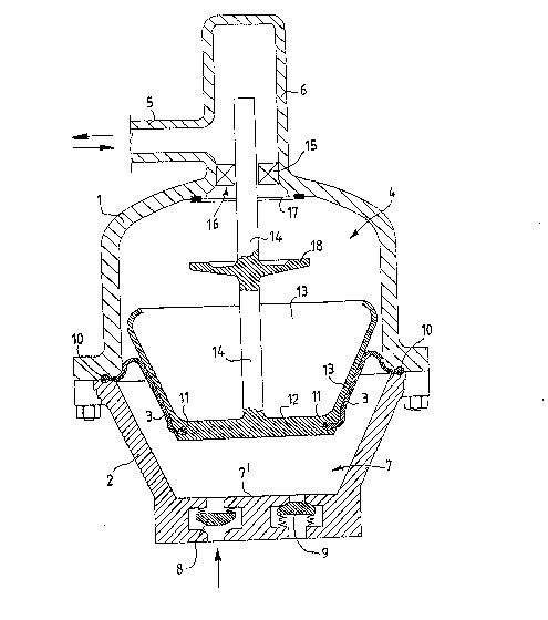
In the figures the reference numerals 1 and 2 indicate
respectively the two half-casings which when bolted together form
the pump casing within which the elastic diaphragm 3 defines an
upper chamber 4 for the hydraulic operating oil which is conveyed
thereto from the feeder not shown in the figure via a feed pump
also not shown in the figure. the duct 5 and a turret 6 connected
to the top of said upper chamber 4 and further defines a lower
chamber 7 of frusto-conical shape ~ith its minor base 7 at the
bottom where the intake valve 8 and the delivery valve 9 for the
fLuid to be pumped are provided.
Said elastic diaphragm 3 is also of frusto-conical shape
corresponding to that of the lower chamber 7 and comprises
thickened edges 10 and 11 which are inserted into suitable
cavities provided in the pump casing l. 2 and in a rigid central
disc 12 respectively. Specifically. the major-diameter edge 10 of
the elastic diaphragm 3 is connected to the pump casing 1 2 and
2~ the minor-diameter edge 11 of the diaphragm is connected to said
rigid disc 12.
Said rigid central disc 12 is also provided on its periphery with a
. . ' : . .
207~40~
frusto-conical surface 13 which acts as a support for the
underlying elastic diaphraem 3, and is rigid with a vertical guide
rod 14 which is itself upperly guided by vertical guides 15
supported in said turret 6, the height of which is such as to
S enable the rod 14 to slide vertically during the entire travel of
the disc 12.
Pinally, a seal ring 17 is provided at the top of the upper
chamber 4 at the mouth 16 of said turret 6, to cooperate hith a
shoulder surface 18 rigid with said rod 14.
Pigures 2 and 3 show clearly how the diaphragm 3 curves as it
separates progressively from the frusto-conical support surface
13, and how when the diaphragm attains its upper end of travel
position (see Pigure 3) the connection between the duct 5 and the
upper chamber 4 is interrupted by the protection system formed by
the ring 17 and the shoulder surface 18.
,