Sélection de la langue

Search

Sommaire du brevet 2076400 

Énoncé de désistement de responsabilité concernant l'information provenant de tiers

Une partie des informations de ce site Web a été fournie par des sources externes. Le gouvernement du Canada n'assume aucune responsabilité concernant la précision, l'actualité ou la fiabilité des informations fournies par les sources externes. Les utilisateurs qui désirent employer cette information devraient consulter directement la source des informations. Le contenu fourni par les sources externes n'est pas assujetti aux exigences sur les langues officielles, la protection des renseignements personnels et l'accessibilité.

Disponibilité de l'Abrégé et des Revendications

L'apparition de différences dans le texte et l'image des Revendications et de l'Abrégé dépend du moment auquel le document est publié. Les textes des Revendications et de l'Abrégé sont affichés :

  • lorsque la demande peut être examinée par le public;
  • lorsque le brevet est émis (délivrance).
(12) Demande de brevet: (11) CA 2076400
(54) Titre français: POMPE A DIAPHRAGME CONVENANT PARTICULIEREMENT AUX FLUIDES CONTENANT DES GAZ
(54) Titre anglais: DIAPHRAGM PUMP, PARTICULARLY SUITABLE FOR GAS-CONTAINING FLUID
Statut: Réputée abandonnée et au-delà du délai pour le rétablissement - en attente de la réponse à l’avis de communication rejetée
Données bibliographiques
(51) Classification internationale des brevets (CIB):
  • F04B 15/00 (2006.01)
  • F04B 43/00 (2006.01)
  • F04B 43/06 (2006.01)
(72) Inventeurs :
  • ESPOSITO, GIANCARLO (Italie)
  • PAGLI, ENZO (Italie)
(73) Titulaires :
  • NUOVOPIGNONE - INDUSTRIE MECCANICHE E FONDERIA S.P.A.
  • AGIP S.P.A.
(71) Demandeurs :
  • NUOVOPIGNONE - INDUSTRIE MECCANICHE E FONDERIA S.P.A. (Italie)
  • AGIP S.P.A. (Italie)
(74) Agent: ROBIC AGENCE PI S.E.C./ROBIC IP AGENCY LP
(74) Co-agent:
(45) Délivré:
(22) Date de dépôt: 1992-08-19
(41) Mise à la disponibilité du public: 1993-03-07
Licence disponible: S.O.
Cédé au domaine public: S.O.
(25) Langue des documents déposés: Anglais

Traité de coopération en matière de brevets (PCT): Non

(30) Données de priorité de la demande:
Numéro de la demande Pays / territoire Date
MI91 A 002369 (Italie) 1991-09-06

Abrégés

Abrégé anglais


CASE 3438
IMPROVED DIAPHRAGM PUMP, PARTICULARLY SUITABLE FOR GAS-CONTAINING
FLUID
Abstract
A diaphragm pump for gas-containing fluids. in which the chamber
for the fluid to be pumped is of frusto-conical shape
corresponding to the elastic diaphragm, the minor-diameter edge of
which is connected to a rigid central disc provided at its
periphery with a frusto-conical support surface for the underlying
diaphragm. A protection system is provided for the elastic
diaphragm.

Revendications

Note : Les revendications sont présentées dans la langue officielle dans laquelle elles ont été soumises.


-7-
CLAIMS
1. A diaphragm pump suitable for gas-containing fluids,
comprising a pump casing divided internally by an elastic
diaphragm into a lower chamber provided with an intake valve and a
delivery valve for the fluid to be pumped, and an upper chamber
for the hydraulic operating oil, characterised in that said lower
chamber is of frusto-conical shape with its minor base below, this
shape corresponding to the shape of said elastic diaphragm the
major-diameter edge of which is connected to the pump casing
whereas its minor-diameter edge is connected to a rigid central
disc provided at its periphery with a corresponding frusto-conical
support surface for the underlying elastic diaphragm, said disc
being rigid with a vertical rod guided upperly by vertical guides
supported within a turret connected to the top of said upper pump
chamber and of such a height as to enable the rod to slide
vertically during the entire travel of the plate, said turret
being connected to the hydraulic operating oil feeder.
2, A diaphragm pump as claimed in claim 1, characterised in
that a seal ring is provided at the top of the upper pump chamber
at the mouth of said turret, to cooperate with a shoulder surface
rigid with said rod when this latter reaches its upper end of
travel position.

Description

Note : Les descriptions sont présentées dans la langue officielle dans laquelle elles ont été soumises.

207~0~
CASE 3438
IMPRO-'ED DIAPHRAGM PUMP, PARTICULARLY SUITABLE POR GAS-CONTAINING
PLUID
This invention relates to a new diaphragm pump which by preventing
the diaphragm undergoing deleterious abnormal deformation or
puckering allows effective, long-lasting and reliable pumping of
fluids with any gas content.
From the state of the art and more precisely from the preceding
European Patent No. 0250026 of April ~, 1992 of the present
applicantl a device is already known for
specifically pumping fluids of high gas content by means of
diaphragm pumps, ie pumps in which an elastomeric diaphragm
separates the fluid to be handled from the hydraulic operating
oil. For this purpose said known pumps use substantially
hemispherical internal elastic diaphragms having a thickness which
decreases from their edge, fixed to the centre plane through the
pump casing, to their centre, and are reinforced by embedded
fabric and a series of metal rings arranRed concentrically
parallel to the plane on which the diaphragm is fixed to the pump
casing, said rings of the series having a cross-section which
decreases from the edge towards the centre of the diaphragm.
Experience has shown that this known type of diaphragm pump has a

- 2076~00
-- 2 --
series of drawbacks. of which the most important is related eo the
arising of abnormal deformation in a critical region of the
diaphragm located in proximity to its connection to the pump
casing, where failure occurs due to fatigue. In substance, it has
been found that following the varying shape assumed by the
diaphragm during pump operation, deformation occurs in said
critical diaphragm region in the form of wrinkles which travel
along said region to cause fatigue failure triggered by small
defects which are always present and are difficult to eliminate.
even with very careful manufacturing processes.
A further drawback of said known diaphragm pump is that the
elastic diaphragm presses directly against the holes provided for
housing the intake and delivery ~alves for the fluid to be pumpedt
the edges of these holes then inevieably fracturing, as has been
found in practice.
The obiect of the present invention i8 to obviate said drawbacks
by providink a diaphragm pump for pumping gas-containing ~luids
,
; ~ which does not give rise to any fracturing of the diaphragm.
Thi- is substantially atcained by using an elastic diaphragm o~
fruséo-conical instead of hemispherical shape. which operates in a
, , , :
lower pump chamber of corresponding frusto-conical shape, said
frusto-conical diaphragm being connected by its major-diameter
;edge~to~the pump casing and by its minor-diameter edge to a rigid
central disc provided at its periphery with a corresponting
frusto-conical support surface for the underlying elastic
diaphraRm.~ Again. as said central disc has a not indif~erent
mass, its position must always be precisely deeined by a rod
w~
.~ , . ,:
,
:
.. ; . :, ' `, :. .
. , - : , .
.
.~

2076~0Q
-- 3 --
vertically rigid with the disc, said rod being guided upperly by
guides which ensure regular vertical sliding of the disc without
any misalignment which could cause undesirable abnormal stressing
of the diap~ragm.
This reliably obviates the danger of fracture of the diaphragm by
the valve holes. these no longer making contact with the diaphragm
as they lie below said ri~id central disc. In addition, when
fluid intake begins, the diaphragm pulled by the action of the
hydraulic operating oil does not close in the form of a bag about
the disc to create the deleterious puckering, but simply rests on
the frusto-conical support surface to hence maintain its shape,
its deformation then taking place without the creation of
puckering. More specifically, the entire frusto-conical diaphragm
rests against the support surface as soon as pulling begins and
then separates gradually from said surface and curves towards its
connection to the pump casing, until it gradually rests on the
cylindrical wall of the upper pump chamber as the disc-rod system
is raised towards its upper end-of-travel position.
~lence, the diaphragm pump suitable for gas-containing fluids,
comprising a pump casing divided internally by an elastic
diaphragm into a lower chamber provided with an intake valve and a
delivery valve for the fluid to be pumped. and an upper chamber
for ehe hydraulic operatin~ oil. is characterised according to the
present invention in that said loher chamber is of frusto-conical
shape with its ninor base below. this shape corresponding to the
shape of said elastic diaphragm the major-diameter edge of which
is connected to the pump casing whereas its minor-diameter edge is
......... .
,- ' '' ' :' ~ :
-;:

2~76~
connected to a rigid central disc provided at its periphery with a
corresponding frusto-conical support surface for the underlyillg
elastic diaphragm, said disc being ri8id with a vertical rod
guided upperly by vertical guides supported within a turret
connected to the top of said upper pump chamber and of such a
height as to enable the rod to slide vertically during the entire
travel of the plate. said turret being connected to the hydraulic
operating oil feeder.
Again, to prevent oil continuing to be drawn from the upper
chamber even after the disc has reached the top of its upward
travel because of an always possible malfunction of the intake
reversal system for the pump hydraulic oil, which in effect has
occurred in practice and which by creating a considerable pressure
difference between the two chambers would fracture the diaphragm
due to exces6 pressure, according to a further characteristic of
the present invention an elastic diaphragm protection device is
provided, in the form of a seal rin~ provided at the top of the
upper pump chamber at the mouth oE said turret, to cooperate with
a shoulder surface rigid with said rod when this latter reaches
its upper end of travel position.
In this manner, when the disc and hence the rod reach their upper
end of travel position, said shoulder surface ma~es contact with
said seal r;ng to thus isolate the upper pump chamber so that
nothing can happen to the diaphragm even if the hydralllic oil pump
should continue to draw.
The invention is described in detail hereinafter wi~h reference to
the accompanying drawings, which illustrate a preferred embodiment
... .
.. :.

2076~0~
;
thereof given by way of non-limiting e~ample in that technical or
constructional modifications can be made thereto but without
leaving the scope of the~present inveneion.
In said drawings:
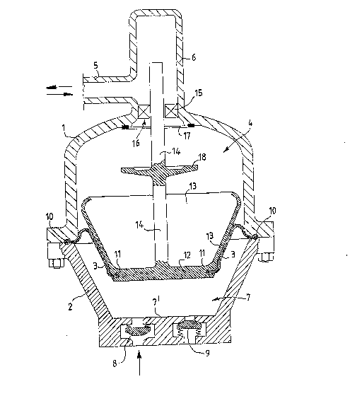
~igure 1 is a front sectional view of a diaphragm pump constructed
in accordance with the invention:
~igures 2 and 3 are views analogous to Figure 1. showing different
stages in the operation of the pump according to the invention.
In the figures the reference numerals 1 and 2 indicate
respectively the two half-casings which when bolted together form
the pump casing within which the elastic diaphragm 3 defines an
upper chamber 4 for the hydraulic operating oil which is conveyed
thereto from the feeder not shown in the figure via a feed pump
also not shown in the figure. the duct 5 and a turret 6 connected
to the top of said upper chamber 4 and further defines a lower
chamber 7 of frusto-conical shape ~ith its minor base 7 at the
bottom where the intake valve 8 and the delivery valve 9 for the
fLuid to be pumped are provided.
Said elastic diaphragm 3 is also of frusto-conical shape
corresponding to that of the lower chamber 7 and comprises
thickened edges 10 and 11 which are inserted into suitable
cavities provided in the pump casing l. 2 and in a rigid central
disc 12 respectively. Specifically. the major-diameter edge 10 of
the elastic diaphragm 3 is connected to the pump casing 1 2 and
2~ the minor-diameter edge 11 of the diaphragm is connected to said
rigid disc 12.
Said rigid central disc 12 is also provided on its periphery with a
. . ' : . .

207~40~
frusto-conical surface 13 which acts as a support for the
underlying elastic diaphraem 3, and is rigid with a vertical guide
rod 14 which is itself upperly guided by vertical guides 15
supported in said turret 6, the height of which is such as to
S enable the rod 14 to slide vertically during the entire travel of
the disc 12.
Pinally, a seal ring 17 is provided at the top of the upper
chamber 4 at the mouth 16 of said turret 6, to cooperate hith a
shoulder surface 18 rigid with said rod 14.
Pigures 2 and 3 show clearly how the diaphragm 3 curves as it
separates progressively from the frusto-conical support surface
13, and how when the diaphragm attains its upper end of travel
position (see Pigure 3) the connection between the duct 5 and the
upper chamber 4 is interrupted by the protection system formed by
the ring 17 and the shoulder surface 18.
,

Dessin représentatif
Une figure unique qui représente un dessin illustrant l'invention.
États administratifs

2024-08-01 : Dans le cadre de la transition vers les Brevets de nouvelle génération (BNG), la base de données sur les brevets canadiens (BDBC) contient désormais un Historique d'événement plus détaillé, qui reproduit le Journal des événements de notre nouvelle solution interne.

Veuillez noter que les événements débutant par « Inactive : » se réfèrent à des événements qui ne sont plus utilisés dans notre nouvelle solution interne.

Pour une meilleure compréhension de l'état de la demande ou brevet qui figure sur cette page, la rubrique Mise en garde , et les descriptions de Brevet , Historique d'événement , Taxes périodiques et Historique des paiements devraient être consultées.

Historique d'événement

Description Date
Inactive : CIB de MCD 2006-03-11
Demande non rétablie avant l'échéance 2000-08-21
Le délai pour l'annulation est expiré 2000-08-21
Lettre envoyée 2000-08-09
Inactive : Renseign. sur l'état - Complets dès date d'ent. journ. 1999-10-04
Inactive : Abandon.-RE+surtaxe impayées-Corr envoyée 1999-08-19
Réputée abandonnée - omission de répondre à un avis sur les taxes pour le maintien en état 1999-08-19
Lettre envoyée 1999-08-13
Inactive : Lettre officielle 1999-08-13
Lettre envoyée 1998-08-03
Demande publiée (accessible au public) 1993-03-07

Historique d'abandonnement

Date d'abandonnement Raison Date de rétablissement
1999-08-19

Taxes périodiques

Le dernier paiement a été reçu le 1998-07-09

Avis : Si le paiement en totalité n'a pas été reçu au plus tard à la date indiquée, une taxe supplémentaire peut être imposée, soit une des taxes suivantes :

  • taxe de rétablissement ;
  • taxe pour paiement en souffrance ; ou
  • taxe additionnelle pour le renversement d'une péremption réputée.

Les taxes sur les brevets sont ajustées au 1er janvier de chaque année. Les montants ci-dessus sont les montants actuels s'ils sont reçus au plus tard le 31 décembre de l'année en cours.
Veuillez vous référer à la page web des taxes sur les brevets de l'OPIC pour voir tous les montants actuels des taxes.

Historique des taxes

Type de taxes Anniversaire Échéance Date payée
TM (demande, 5e anniv.) - générale 05 1997-08-19 1997-07-10
TM (demande, 6e anniv.) - générale 06 1998-08-19 1998-07-09
Titulaires au dossier

Les titulaires actuels et antérieures au dossier sont affichés en ordre alphabétique.

Titulaires actuels au dossier
NUOVOPIGNONE - INDUSTRIE MECCANICHE E FONDERIA S.P.A.
AGIP S.P.A.
Titulaires antérieures au dossier
ENZO PAGLI
GIANCARLO ESPOSITO
Les propriétaires antérieurs qui ne figurent pas dans la liste des « Propriétaires au dossier » apparaîtront dans d'autres documents au dossier.
Documents

Pour visionner les fichiers sélectionnés, entrer le code reCAPTCHA :


Pour visualiser une image, cliquer sur un lien dans la colonne description du document (Temporairement non-disponible). Pour télécharger l'image (les images), cliquer l'une ou plusieurs cases à cocher dans la première colonne et ensuite cliquer sur le bouton "Télécharger sélection en format PDF (archive Zip)" ou le bouton "Télécharger sélection (en un fichier PDF fusionné)".

Liste des documents de brevet publiés et non publiés sur la BDBC .

Si vous avez des difficultés à accéder au contenu, veuillez communiquer avec le Centre de services à la clientèle au 1-866-997-1936, ou envoyer un courriel au Centre de service à la clientèle de l'OPIC.

({010=Tous les documents, 020=Au moment du dépôt, 030=Au moment de la mise à la disponibilité du public, 040=À la délivrance, 050=Examen, 060=Correspondance reçue, 070=Divers, 080=Correspondance envoyée, 090=Paiement})


Description du
Document 
Date
(aaaa-mm-jj) 
Nombre de pages   Taille de l'image (Ko) 
Abrégé 1993-03-06 1 10
Dessins 1993-03-06 3 68
Revendications 1993-03-06 1 24
Description 1993-03-06 6 175
Dessin représentatif 1999-06-16 1 24
Rappel - requête d'examen 1999-04-19 1 117
Courtoisie - Lettre d'abandon (taxe de maintien en état) 1999-09-15 1 187
Courtoisie - Lettre d'abandon (requête d'examen) 1999-09-29 1 172
Correspondance 2000-08-08 1 24
Correspondance 1999-08-12 1 20
Correspondance 1998-08-02 1 20
Taxes 1998-07-08 1 37
Taxes 1996-07-17 1 40
Taxes 1995-04-30 1 42
Taxes 1994-07-13 1 45
Courtoisie - Lettre du bureau 1997-05-27 1 15
Correspondance reliée au PCT 1997-04-23 1 25
Courtoisie - Lettre du bureau 1997-05-27 1 12
Correspondance reliée au PCT 1997-11-11 3 50
Courtoisie - Lettre du bureau 1997-12-15 1 12
Courtoisie - Lettre du bureau 1997-12-15 1 13