Note: Descriptions are shown in the official language in which they were submitted.
2076~20
.~_
WINDSHIELD FOR HEAD-UP DISPLAY SYSTEM
Background of the Invention
1. Field of the Invention
This invention relates to a windshield for a head-up display
system and in particular to an automotive windshield functioning as
15 the combiner for the head-up display system and having a wedged
configuration for some selected portion of the windshield area,
particularly in the viewing area of the head-up display, to eliminate
double imaging.
20 2A. Technical Considerations
A head-up display system is a visual display arrangement
that displays information to a viewer while he simultaneously views
the road and objects outside his vehicle around and through the
display. Head-up display systems are often incorporated into
25 aircraft cockpits for pilots to monitor flight information. More
recently the systems have been used in land vehicles such as cars,
trucks and the like. The display is generally positioned so that the
viewer does not have to glance downward to the vehicle dashboard and
away from the viewing area in front of the vehicle as is required of
30 a vehicle operator viewing vehicle operating information in a vehicle
not having a head-up display.
A head-up display system generally includes a display
projection system, a collimator, and a combiner. The projection
system includes a light source that projects operating information
3~ through the collimator which generally aligns the projected light
rays. The collimated light is then reflected off the combiner, which
is in the vehicle operator's field of view. In this manner, vehicle
2076420
~_ - 2 -
information such as, for example, fuel information and vehicle speed
is displayed within the operator's field of vision through the
windshield and permits the operator to safely maintain eye contact
with the road and other objects outside his vehicle while
5 simultaneously viewing the displayed information. The reflected
images of the display may be focused at a position anywhere from
immediately in front of the vehicle to optical infinity.
Laminated windshields have been used as the combiner in a
head-up display system to reflect a primary display image as taught
10 in U.S. Patent No. 2,264,044 to Lee. However, it has been observed
that a ~econdary image is reflected off the outer surface of the
windshield. This secondary image is superimposed over but offset
from the primary image and reduces the overall image clarity.
It would be advantageous to have a windshield for a head-up
15 display system which functions as a combiner and provides a clear
display image without producing double images when viewing through
the head-up display area, without distorting the view through other
portions of the window not associated with the head-up display
system, and without incorporating additional components with the
20 windshield.
2B. Patents of Interest
U.S. Patent No. 1,871,877 to Buckman teaches a display
system having a glass sheet mounted on the wind~hield or dashboard
25 which reflects instrumentation information to the vehicle operator.
U.S. Patent No. 2,264,044 to Lee teaches a motor vehicle
having an illuminated speedometer display that is reflected off the
inboard surface of the vehicle windshield.
U.S. Patent No. 2,641,152 to M~hfllAkis teaches a vehicle
30 proJection device wherein instrumentation information is reflected
off of a reflecting screen on the inboard surface of the vehicle
windshield. The reflecting surface has a satin finish and can be
metal, glass, or plastic.
U.S. Patent No. 2,750,833 to Gross teaches an optical
35 display system for eliminating double images which occur in reflector
type sights such as those used in aircraft gun sighting
installations. A collimated light beam is polarized and separated
2076420
~_ - 3 -
into two ray branches. One of the two ray branches i8 then
eliminated.
U.S. Patent No. 3,276,813 to Shaw, Jr. teaches a motor
vehicle display system which utilizes a highly reflective coating on
5 the inboard surface of the vehicle windshield to reflect
instrumentation information to the vehicle operator.
U.S. Patent No. 3,446,916 to Abel teaches an image combiner
utilizing a portion of the aircraft window. The inner ~urface
portion of the window is coated with a partially reflective film.
U.S. Patent Nos. 3,554,722, 3,591,261, and 3,647,285 to
Harvey et al. teaches a double glazed glass window structure which
eliminates objectionable fringe patterns produced in this structure
when float glass of non-uniform thickness is utilized. The window
structure includes a pair of spaced apart, float glass sheets one or
15 both of which are tapered from a thick edge to an opposing thin
edge. When both the glass sheets are tapered, the glass sheets are
positioned such that a thick edge of one glass sheet is spaced from a
thin edge of the opposing glass sheet.
U.S. Patent No. 3,697,154 to Johnson teaches an optical
20 viewing system in which images formed on the screen of a cathode ray
tube (CRT) are reflected from a curved mirror having a general
aspheric surface of revolution to a partially reflective combiner
having two nonparallel hyperboloid surfaces, the combiner being
positioned in the normal line of sight of an observer such that a
25 collimated CRT image is reflected from the near surface of the
combiner to the observer's eyes and the combiner being adapted to
transmit light incident from the outside so that the CRT display is
superimposed without parallax on the real world to provide a head-up
display.
U.S. Patent No. 3,870,405 to Hedges teaches a visor for use
an optical element in a helmet-mounted sight having inner and outer
surfaces being sections of ofocal paraboloids of revolution.
U.S. Patent No. 3,899,241 to Malobicky, Jr. et al. teaches a
windshield adapted for use in aircraft and includes a transparent
35 reflective coating on the inboard surface in the center portion of
the forward vision area to form a vision image receiving area.
Il 2076420
_ - 4 -
Vehicle information is reflected off the reflective coating to the
vehicle operator.
U.S. Patent No. 3,940,204 to Withrington and 4,218,111 to
Withrington et al. teach an optical display system utilizing
5 holographic lenses.
U.S. Patent No. 4,261,635 to Freeman teaches a head-up
display system including a holographic combiner positioned inboard of
the vehicle windshield. The hologram i8 disposed substantially
orthogonal to and midway along an axis between the observer's eye
10 position and the projection optics so as to deviate light from an
image produced by the projection optics to the observer eye with
minimal field aberration.
U.S. Patent No. 4,398,799 to Swift teaches a head-up display
system which simultaneously records the pilot's view by reflecting
15 the outside scene and the projected display by reflecting the outside
scene and superimposed display off a mirror mounted on the pilot's
helmet and recording the reflected view with a camera mounted on the
pilot's helmet.
U.S. Patent No. 4,613,200 to Hartman teaches a head-up
20 display system which uses two parallel holographic optical elements
to reflect instrumentation information to the vehicle operator. One
of the elements is made part of or attached to the vehicle windshield.
U.S. Patent No. 4,711,544 to Iino et al. teaches a display
system for a vehicle wherein instrumentation information is reflected
25 off the front glass of the vehicle so that the image display can be
formed in a desired position, aligned with the line of sight of the
driver without obstructing the front sight of the driver.
U.S. Patent No. 4,787,711 and 4,892,386 and European Patent
No. 229,076 to Suzuki et al. teach an on-vehicle head-up display
30 device employing a catoptric system for a windshield glass of an
automobile to project a display image onto an inner surface of the
windshield glass, an optical system for letting a virtual image of
the display image of the display means enter the windshield glass is
adapted to make an angle formed by light beams of the virtual image
35 entering the windshield glass less than a monocular resolving power
and an optical means for correcting parallax of the light beams of
the virtual image is provided between the optical system and the
~ - 5 - ~ ~7~ ~2a
windshield glass to thus eliminate double imaging and binocular
parallax.
Defensive Publication No. T861,037 to Christensen teaches a
tapered or wedged vinyl interlayer for use in laminating windshields
such that the interlayer is thicker at the top of the windshield
than at the bottom of the windshield in order to eliminate double
vision caused by the windshield curvature and angle of installation.
The present disclosure provides a windshield for a head-up
display system that reduces the degree of double imaging that occurs
when a laminated windshield is used as the combiner in the display
system. The windshield functions as a combiner for the head-up
display system without requiring any additional elements or
components to be incorporated onto or into the windshield assembly.
The windshield is constructed such that selected opposing, outer
major surfaces of the windshield are non-parallel with the opposing
outer major surfaces oriented relative to each other so that an
image, projected from a display source and reflected off a first
major surface of the windshield, is substantially superimposed over
or parallel to the same image from the display source reflected off
the opposing outer major surface of the windshield.
In one embodiment, the windshield includes a pair of glass plies
secured to each other by a sheet of thermoplastic interlayer
material. The windshield has opposed outer major surfaces that are
tapered in thickness from one edge to the other. This may be
accomplished by having one or both plies and/or the sheet of
interlayer material tapered in thickness from one edge to the other.
In another embodiment the windshield has a selected area that
has the outer major surfaces of the windshield non-parallel to one
another, and the outer major surfaces of the windshield at the
remaining area generally parallel to one another. In this manner,
the degree of double imaging is reduced in the area where the outer
surfaces are non-parallel to one another, and the optical distortion
B~
~- - 6 - 2~4~
in the remaining area is improved because the outer surfaces are
parallel to one another. This may be accomplished by having one or
both of the glass plies and/or the sheet of interlayer material
partially tapered in thickness such that when the plies and sheet
are joined together, the outer major surfaces of the windshield in
the selected area are nonparallel to one another with the rem~'n;ng
area of the outer major surfaces of the windshield generally
parallel to one another in the area other.
Interlayer containing a wedged or tapered section may be
achieved by casting the interlayer to the desired configuration,
extruding the desired cross sectional thickness, or differentially
stretching the interlayer to the desired shape. When the glass plies
and the interlayer having the tapered section are assembled and
laminated to form a unitary structure, the opposing major surfaces
of the laminate are non-parallel in the area of the tapered section
and offset at a predetermined angle in the vicinity of the tapered
section. The windshield in use is positioned relative to a display
system such that the images generated by light rays from the display
source reflected off the non-parallel opposing major surfaces of the
windshield or laminate are substantially superimposed over or
parallel to each other such that double imaging is reduced if not
eliminated, while the r~m~ln;ng sections of the windshield have the
outer major surfaces substantially parallel to one another to
eliminate or minimize optical distortion of objects viewed through
the rem~;n;ng area of the windshield.
The disclosure also contemplates making the windshields by
joining glass sheets and a sheet of interlayer material to provide a
windshield having the outer surfaces parallel in a first
predetermined area and nonparallel in a second predetermined area.
More particularly in accordance with a first aspect of the
invention there is provided, an article comprising a transparent
substrate having a first major surface, a second opposite major
r,~
- 6a - ~ ~ 7 ~ 4 2 ~
surface, a first predetermined area where opposed major surfaces are
substantially parallel to one another, and a second predetermined
area where opposed major surfaces are nonparallel to one another.
In accordance with a second aspect of the invention there is
provided, a method of making an automotive transparency providing a
pair of glass plies and a sheet of interlayer material each having a
predetermined thickness throughout their length and width; and
securing said pair of plies together about said sheet of interlayer
material to provide a laminate with outer surfaces having a first
predetermined area of constant thickness and second predetermined
area of varying thickness.
Brief Description of the Drawinqs
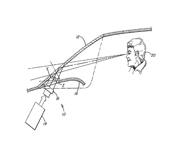
Figure 1 is a schematic of head-up display system for vehicle.
Figure 2 is an enlarged, partial cross-sectional view of Figure
1 illustrating a head-up display using a prior art windshield.
Figure 3 is an enlarged, partial cross-sectional view of Figure
1 illustrating a head-up display using a windshield
4 ~ ~
-- 7 --
incorporating features embodied in the present invention.
Figure 4 is an éxploded cross-sectional view of an alternate
embodiment of the invention.
Figures 5 and 6 are cross-sectional views of alternate
5 embodiments of the invention.
Detailed Descri~tion of the Preferred Embodiments
The present invention relates to the elimination of double
imaging in a head-up display system that uses an automotive
10 windshield as the combiner, but it should be appreciated that the
present invention may be used in any type of combiner having a
laminate construction where double imaging is to be eliminated.
With reference to Figure 1, head-up display 10 system
includes a motor vehicle windshield 12, an image source 14 and a
15 projection assembly 16, preferably mounted immediately beneath the
upper surface of the vehicle dashboard 18 and positioned between the
image source 14 and windshield 12. Light rays emanate from the image
source 14 and are projected onto the windshield 12, which operates as
a combiner as will be discussed later, and reflected into the field
20 of vision of the vehicle operator or observer 20. The light rays
projected onto the windshield 12 are collimated so as to create a
virtual image in front of the car, preferably at about 5 to 50 feet
(3 to 15 meters) in front of the windshield 12.
Although not limiting in the present invention, the image
25 source 14 preferably is a transmissive liquid crystal display (LCD)
that is adequately illuminated to project information carrying light
rays through the projection assembly 16 onto the windshield 12 at a
location within the vehicle operators direct line of sight while
permitting peripheral viewing of the road and objects outside of the
30 vehicle as the operator or observer 20 monitors the display. It is
contemplated that alternative viewing locations will also provide an
effective head-up display for the vehicle windshield. The displayed
image (not shown) may include numerical or graphical symbols
including for example, vehicle speed, fuel level, engine RPMs,
35 temperature, and warning symbols.
The following discussion will be directed towards the use of
a prior art windshield as the combiner in a head-up display system
~ 2076~20
_ - 8 -
which projects an image a finite distance in front of the
windshield. In particular, referring to Figure 2, windshield 30
represents a windshield assembly with the opposing inner and outer
major surfaces of the windshield being parallel to each other for the
5 full length of the windshield, i.e. from the top edge to the opposite
edge and between the side edges. The windshield 30 includes outer
glass ply 32 bonded to inner glass ply 34 by an interlayer material
36. Because the thickness of the interlayer 36 is fairly uniform and
the opposing major surfaces of each glass ply are substantially
10 parallel to each other, i.e., inner surface 37 of the ply 32 is
parallel to its outer surface 38 and inner surface 39 of the ply 34
i8 parallel to its outer surface 40, the outer major surface 38 of
the glass ply 32 is parallel to the outer major surface 40 of the
glass ply 34 after the glass plies 32 and 34 and interlayer 36 are
15 laminated together to form a unitary structure. Although not
limiting in the present invention, for the purposes of illustration,
surfaces 38 and 40 are assumed to be planar in the following
discussion. However, the surfaces may be non-planar, as will be
discussed later.
With continued reference to Figure 2, a light ray A from
image source 14 is directed along line 42 and a portion of the light
ray A is reflected off surface 40 of the ply 34 along line 44 to eye
46 of the vehicle operator 20. Additional light rays from the source
14 are directed along additional lines. For example, light ray B is
25 directed along line 48 and a portion of the light ray B is reflected
off the surface 40 along line 50 toward the vehicle operator 20.
However, the ray B along the line 50 is not directed to the eye 46 as
shown in Fig. 2 so it will not be detected by the observer 20.
A portion of the light ray B which is directed along line 48
30 will enter the windshield assembly 30 and be refracted along line
52. The angular difference between the lines 48 and 52 depends on
the angle of refraction as the light ray passes through the air and
into the glass ply 34. The angle of refraction in turn depends, in
part, on the angle at which ray B is incident on the surface 40 and
35 the relative densities of the air and the glass. The ray B passes
through the windshield assembly 30 and a portion of the light ray B
i8 reflected off the surface 38 of the ply 32 along line 54. It is
1 2076~20
-
g
assumed that the refractive index of interlayer 36 is essentially the
same as that of the glass plies 32 and 34 so that the light rays are
not redirected as they pass through the wlndshield assembly 30 along
lines 52 and 54.
A portion of the light ray B leaves the windshield assembly
30 at the surface 40 of the glass ply 34 where the direction of the
light is again changed due to the difference in the refraction index
between the windshield assembly 30 and the air, as discussed earlier,
and directed along line 56 to the operator's eye 46. Because the
10 light rays A and B received by the eye 46 from the image source 14
are along two different lines, i.e. lines 44 and 56, which are
convergent toward one another to the eye of the observer 20 rather
than parallel, the observer 20 will perceive two offset images where
in fact there is only one image source 14. The first image 58, or
15 virtual image, is the image seen by the observer Z0 from the portion
of the light ray A directed along line 44. The second image 60 is
the image seen by the observer 20 from the portion of the light ray B
directed along line 56.
When viewing both images, the virtual image 58 will appear
20 brighter than the second image 60 because a greater portion of the
light from the image source 14 which was initially directed along
line 42 will be directed along line 44 as compared to the amount of
light initially directed along line 48 and which is finally directed
along line 56 to the observer 20. This condition of seeing two
25 offset images is commonly referred to as double imaging, or ghost
imaging, and results when the outer surfaces of the windshield
assembly, i.e. surfaces 38 and 40 of windshield assembly 30, are
parallel to each other. Stated another way, double imaging occurs
when the light rays A and B, projected from image source 14 onto
30 parallel surfaces 38 and 40, are directed toward the eye of the
observer along non-parallel lines, i.e., lines 44 and 56 which
converge toward each other to the eye 46 of the operator 20.
In order to reduce the amount of double imaging in the
windshield assembly 30, the present invention modifies the windshield
35 structure by adjusting the spaced relationship of the surfaces 38 and
40 relative to one another such that the portion of the light rays A
and B directed to the eye of the observer are superimposed over or
o
-- 10 --
parallel to one another. Although not limiting in the present
invention, referring to Figure 3 which illustrates an embodiment of
the present invention, windshield 130 includes outer glass ply 132
bonded to inner glass ply 134 by an interlayer material, e.g., a
5 thermoplastic material 136 along inner major surfaces 137 and 139 of
plies 132 and 134, respectively. The interlayer 136 is fabricated in
such a way as to gradually taper in thickness from top to bottom of
the windshield with the thicker section at the top edge as reviewed
in Figure 3. In other alternate embodiments of the invention to be
10 discussed in detail below, the interlayer may be of tapered thickness
for a selected portion and of constant thickness for other portions
to provide a windshield that has the outer major surfaces of the
windshield nonparallel to one another in the area having the section
of the interlayer havin~ the tapered thickness and outer major
15 surfaces of the windshield parallel to one another in the areas
having the sections of the interlayer having the constant thickness.
As a result of the "wedged" shape section of the interlayer,
when the windshield components are assembled and laminated, outer
~major surface 138 of glass ply 132 and outer major surface 140 of
20 glass ply 134 will be non-parallel. It has been found that by
controlling the amount by which the glass plies 132 and 134 of the
windshield 130 are offset from each other, the double imaging
encountered when using a windshield as shown in Figure 2 as a
combiner can be reduced in a manner to be discussed below. The
25 actual wedge angle X required to reduce the double imaging depends,
in part, upon the thickness of the windshield, the windshield
materials, and the relative positions and orientations of the image
source 14, the windshield 130 and the vehicle operator 20. Although
not limiting in the present invention, the interlayer 136 can be cast
30 in place to provide the desired wedge angle X. As an alternative,
the interlayer 136 can be differentially stretched in any convenient
manner known in the art, such as that disclosed in U.S. Patent No.
4,201,351 to Tolliver and U.S. Patent No. 4,554,713 to Chabel,
~ith continued reference to Figure 3, the discussion will
35 now be directed to the elimination or minimization of double images
or ghost images using a windshield that has wedge or taper, i.e.,
B
2076420
11
nonparallel outer surfaces. Light ray Al from the image source 14 is
directed along line 142 and a portion of the light ray Al is
reflected off the surface 140 along line 144 to the eye 46. Another
portion of the light ray Bl directed along line 148 is reflected from
5 the surface 140 along line 150 such that it i8 not seen by the
observer 20 as was discussed for the portion of the light ray B
reflected from the surface 40 along line 50 of the prior art
arrangement shown in Fig. 2. The remaining portions of the ray Bl
are refracted through the glass plies 132 and 134 and the interlayer
10 136 along line 152 and refracted as it leaves the assembly 130 to the
observer's eye 46 along line 144 in a similar manner as that
discussed for the ray B shown in Figure 2. However, unlike the
windshield assembly 30 in Figure 2 wherein the line 56 from the ray B
is along a different orientation than line 44 from ray A, in the
15 present invention as shown in Figure 3, the wedge angle X is such
that the refracted light from light ray Bl exits the assembly 130
along the line 144, i.e., parallel or superimposed over the light
from ray Al reflected off the surface 140 of the glass ply 134 also
moving along the line 144. As a result, the image viewed by the
20 observer 20 resulting from light rays Al and Bl are superimposed over
or parallel to each other 80 that there is viewed only a single image
158.
It should be appreciated that in a windshield assembly, the
surfaces 138 and 140 of the glass plies 132 and 134, respectively,
25 are often not planar but rather have a curved configuration.
However, the amount of relative curvature in the windshield assembly
130 within the small area used as the combiner is relatively small so
that the area within the combiner portion of the windshield 130 is
nearly planar. Furthermore, if required due to excessive curvature
30 of the windshield within the combiner area, the image from the image
source 18 can be distorted, for example by incorporating additional
lens arrangements (not shown) into the projection assembly 16 (shown
only in Figure 1) to account for the curvature of the windshield
surfaces.
In one particular embodiment of the invention, the
windshield 130 includes 0.090 inch (2.3 mm) thick glass plies and two
polyvinylbutryl interlayer plies. Each interlayer ply is originally
4 ~. ~
- 12 -
0.020 inches (0.05 mm) thick and is differentially stretched so that
each interlayer ply has a taper of approximately 0.003 inches (0.076
mm) over a 36 inch (91 cm) interlayer width for a combined thickness
differential of approximately 0.006 inches (0.152 mm) from the top to
5 the bottom edge (as viewed in Figure 3) when incorporated into the
windshield 130. Referrin~ to Figure 1, it has been observed that a
windshield of this construction, mounted in a vehicle at an
installation angle Y of approximately 30~ from the horizontal with an
angle of incidence Z between the windshield 12 and image source 14 of
10 approximately 65~ significantly reduces the amount of double imaging
in a head-up display system as compared to a conventional windshield
having a non-wedged configuration.
Although the windshield configuration 130
as shown in Figure 3 includes two glass sheets each having
15 generally parallel opposing major surfaces and a tapered interlayer
ply, based on the teachings of this disclosure, it is obvious to one
skilled in the art that other windshield configurations can be used
to provide a wedged windshield configuration similar to that shown in
Figure 3. In particular, referring to Figure 4, one or both of the
20 glass plies 232 and 234 may be provided with a taper such that when
the assembly 230 is laminated to form a unitary structure using a
non-stretched interlayer 236, opposing surfaces 234 and 236 of the
windshield 230 are non-parallel and are oriented relative to each
other so as to eliminate the double imaging. It is further
25 contemplated that one or more tapered interlayer may be used in
combination with one or more tapered glass plies so that the final
laminated assembly provides a required windshield construction having
the configuration required to reduce double imaging. In other words,
the invention is not directed to providing glass plies and a sheet of
30 interlayer that does or doesn't have a taper as long as a~ter the
plies are secured about the interlayer the outer surfaces of the
windshield are nonparallel so that the portions of the light rays
and Bl directed toward the eye of the observer are parallel or
superimposed over one another along the line 144 as shown in Figure 3.
It has been contemplated that the use of a partial wedge may
be preferred to solve the problem of double imaging by use of a wedge
area in the head-up display area of the windshield while at the same
~3
; 2076420
-
- 13 -
time solving the ~n; 'zing optical distortions associated with
viewing objects through wedged glass. More particularly, it has been
noted that the use of non-tapering or non-wedged areas of laminated
glass, i.e., outer surfaces of the laminated windshield substantially
5 parallel to one another for the upper portion of a windshield as
mounted with the tapering or wedged areas at or near the bottom of
the windshield as mounted, improves the optics of the windshield.
More particularly, a vehicle operator viewing an object such as a
traffic light at a 45~ angle through an upper area of the windshield
10 encounters less double vision of objects viewed through a non-tapered
or non-wedged windshield than a tapered or wedged windshield.
However, a vehicle operator viewing an object such as a head-up
display at a 90~ angle through the bottom portion of the windshield
will observe a double image for the reason discussed above. Thus, a
15 windshield having a partial wedge area such as the windshield types
shown in Figures 5 and 6 would be advantageous over a windshield of
the type shown in Figure 3 that has a taper or wedge from the top
edge of the windshield to the opposite or bottom edge.
In the following discussions regarding Figures 5 and 6, the
20 left hand side of windshields 330 and 430 as viewed in Figures 5 and
6, respectively, is the top end of the windshield as mounted in a
vehicle and the right side as viewed in Figures 5 and 6 is the
opposite or bottom end of the windshield as mounted. With reference
to Figure 5, the windshield 330 has glass plies 332 and 334 secured
25 to each other about interlayer 336. The windshield 330 has a partial
wedge by providing outer surface 338 of the glass ply 332 nonparallel
to the outer surface 340 of glass ply 334 in the mid-area 337 and the
outer surfaces 338 and 340 of the glass plies 332 and 334,
respectively, in the upper area 342 and lower area 344 parallel to
30 one another. This may be accomplished by providing the glass plies
332 and 334 with a constant thickness throughout their length, i.e.
from the top edge to the bottom edge of the windshield and width,
i.e. from one side to the other side (only one side shown in Figure 5
and 6), and the portions of interlayer 336 in the top and bottom
35 areas 342 and 344, respectively, of the windshield 330 with constant
thickness and the portion of the interlayer in the mid-area 337 with
a tapered thickness.
2076~20
-
- 14 -
A windshield of the type shown in Figure 5 may be
constructed as follows. Such a windshield 330 would include a pair
of 0.090 inch (2.3 mm) thick glass plies 332, 334. The glass plies
would each have a length of approximately 45 inches (114.3 cm).
5 A sheet 336 of polyvinylbutyral would be differentially stretched
and cut to fit between the glass plies. The polyvinylbutyral sheet
336 would have a constant thickness of .034 inches (.086 cm) from the
top edge to a distance of 25 inches (63.5 cm) therefrom (top area
342); a taper defined by the interlayer 336 would have a thickness of
10 .034 inches (.086 cm) at a point spaced 25 inches (63.5 cm) from the
top edge of the windshield and a thickness .030 inches (.076 cm) from
the top of a windshield top edge of 37 inches (94 cm) (mid area 337).
Figure 6 illustrates another embodiment of the invention
directed to partial wedging of the windshield. The windshield 430
15 shown in Figure 6 has a pair of glass plies 432 and 434 about an
interlayer 436. The thickness of the glass plies and interlayer are
selected to provide the windshield with a lower area 437 having outer
surface 438 and 440 nonparallel to one another and upper area 439
having outer surfaces 438 and 440 of the windshield parallel to one
20 another. In Figure 6, this arrangement may be achieved by using
glass plies 432 and 434 of constant thickness and a sheet of
interlayer material that has constant thickness at its upper portion
and a taper at its lower portion.
A windshield of the type shown in Figure 6 was constructed
25 as follows. The windshield 430 included a pair of 0.090 inch (2.3
mm) thick glass plies 432, 434. The glass plies each had a length of
45 inches (114.3 cm). A sheet 436 of polyvinylbutyral was
differentially stretched and cut to fit between the glass plies. The
sheet 436 had a constant thickness of .038 inches (.097 cm) from the
30 top edge to a distance of 25 inches (63.5 cm) therefrom (upper area
439) and a taper defined by the interlayer having a thickness of
.038 inches (.097 cm) at a point spaced 25 inches (63.5 cm) from the
top edge to a thickness .030 inches (.076 cm) at the bottom edge (the
lower area 437).
Referring to Figure 1, it has been observed that windshields
of the construction discussed above and shown in Figures 5 and 6
mounted in a vehicle at an installation angle Y of approximately 30~
2076420
_
- 15 -
with an angle of incident Z between the mid-section 337 of the
windshield 330 or the lower area 437 of the windshield 430 and the
image source 14 of approximately 65~ significantly reduces the amount
of double imaging in a head-up display system as compared to the
5 prior art windshield having a non-wedged configuration while
maintaining the optical properties of the prior art windshield in the
upper and lower areas 342 and 344 of the windshield 330 and the upper
area 439 of the windshield 430.
In the windshield construction of the type shown in Figures
10 5 and 6, the non-tapered section, e.g., areas 342 and 344 of the
windshield 330 of Figure 5 and area 448 of the windshield 430 of
Figure 6, there was minimal, if any, optical distortion because the
outer surfaces of the windshield in those portions were parallel.
As can now be appreciated, the partial wedging of the
15 windshields 330 and 430 can be attained in any convenient manner.
For example, one or more of the glass plies may have varying
thicknesses and/or the interlayer may have varying thicknesses in the
wedged sections, i.e. area 337 of the windshield 330 and area 437 for
the windshield 430. The requirement in the practice of the invention
20 is that when the windshield i8 assembled using the glass plies and
interlayer, selected areas of the windshield have the outer edges
nonparallel to one another while the other areas have the outer
surfaces parallel. As used herein and as can now be appreciated the
term "outer surface parallel" does not require the surfaces to be
25 perfectly parallel to one another but have the degree of parallelism
that is usually observed in the prior art windshields to which this
invention is directed. Further, the invention was discussed with the
windshield having the tapered area from side to side; however, as can
now be appreciated only the area in front of the observer may have
30 the partial wedge with the remaining area of the windshield having
parallel outer surfaces.
Further from the foregoing discussion, it can now be
appreciated that the invention may be practiced by tapering selected
sections of a sheet of interlayer, by providing a piece of tapered
35 interlayer over a sheet of interlayer having a constant thickness, by
providing a glass ply having selected portions tapered by adding a
piece of tapered glass to a glass ply having a constant thickness
- 16 -
and/or by removing glass, e.g., by grinding and polishing a selected
section of the glass.
Still further, the invention may be practised using colored
glass of the type known in the art, e.g. such as that taught in U.S.
5 Patent No. 4,792,536, may be used on windshields having environmental
coatings, e.g., of the type taught in U.S. Patent No. 4,610,771, may
be used on heatable windshields, e.g., of the type taught in U.S.
Patent No. 4,820,902 or may be used with a coating on any surface of
the glass plies at least in the area of the windshield having
10 nonparallel outer surfaces to enhance the image, e.g., coatings of
the type taught in U.S. Patent No. 3,899,241,
The forms of this invention shown and described in this
disclosure represent illustrative preferred embodiments and various
modifications thereof. It is understood that various changes may be
15 made without departing from the scope of the invention as defined by
the claimed subject matter which follows.
B