Note: Descriptions are shown in the official language in which they were submitted.
- 20764~6
S P E C I F I C A T I O N
This invention relates in general to a fast change set-
up of work on a work support device and in particular to an
improved work support.
Hydraulic and pneumatic interlocks for upper and lower
work holders are known, but they do not disclose the
mechanical features of the present invention.
The invention provides a lower work support formed with
moveable locking bolts which are controlled by a shaft that
carries cams so as to move the locking bolts and an upper
support which has locking pins formed with grooves which are
receivable in the lower work support such that when the
locking shaft is rotated, cams will cause the locking bolts
to engage the grooves in locking pins of the upper work
support to lock the upper and lower work supports together so
that a work piece attached to the upper work support can be
machined.
A manually controlled shaft which carries four cams that
respectively engage the four locking bolts provide a rapid and
simple mechanism for locking the upper and lower work supports
together. After the work piece has been machined, the upper
work support can be removed from the lower work support by
rotating the locking handle and another upper support with a
new work piece can be then mounted on the work support and the
second work piece can then be machined.
The invention provides that the workpieces can be set up
on an upper work support member as another workpiece is being
machined which allows faster production of finished parts.
Other objects, features and advantages of the invention
will be readily apparent from the following description of
certain preferred embodiments thereof taken in conjunction
with the accompanying drawings although variations and
- 1 - ,~ '
-- 2076486
modifications may be effected without departing from the
spirit and scope of the novel concepts of the disclosure, and
in which:
ON THE DRAWINGS
FIG. 1 is a perspective view illustrating the invention;
FIG. 2 is a sectional view on lines II-II from FIG. 1
with the upper and lower work supports connected together;
FIG. 3 is a view showing the upper and lower work
supports separated;
FIG. 4 is a top plan view of the lower work support; and
FIG. 5 is a bottom plan view of the lower work support.
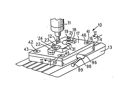
FIGS. 1, 2 and 3 illustrate the novel work support member
10 which comprises an upper support member 16 and a lower
support member 14 which can be mounted to a table or bed 13
of a machine which might have a motor 11 upon which a cutting
tool 12 is mounted. A workpiece 31 which is to be machined
with the cutting tool 12 is mounted on the top surface 17 of
the upper workpiece holder 16 by clamps 18 and 22 which have
workpiece engaging ends 28 and 29. Bolts 19 and 23 receive
nuts 21 and 24 so s to hold the workpiece clamps 18 and 22
down against the workpiece 31. Block members 26 and 27 of
different sizes may be mounted between the clamps 18 and 22
and the su-face 17 of the upper workpiece support member 16,
as shown. Mounted adjacent the four corners of the upper
workpiece supporting member 16 are locking pins such as 33 and
34 which are shown in FIGS. 2 and 3 which are mounted adjacent
the rear edge of the upper workpiece support 16 relative to
FIG. 1. Two additional pins are mounted adjacent the front
edge relative to FIG. 1 of upper workpiece support 16.
The pin 33 is attached to the member 16 by a T-shape
member 43 which is received in an opening in the upper surface
17 of member 16 and a bolt 39 passes through an opening in the
2076486
'_
member 43 and extends into the pin 33 as shown in FIGS. 2 and
3 to lock it to the member 16. 1ikewise a member 44 is
received in an opening in the upper surface 17 of member 16
and a set screw 41 extends through the member 44 and locks the
pin 34 to the member 16. Also extending from the lower
surface 32 of the upper workpiece support 16 are guide pins
60 and 70 which are receivable in openings 80 and 90 of the
lower work support member 14 as shown in FIG. 4 so as to
properly align the upper and lower members 16 and 14.
Each of the four pins 33 and 34 and the two pins mounted
at the other end of the upper support member 16 are formed
with grooves such as the grooves 51 and 54 of the pins 33 and
34 and an enlarqed head portion 52 and 55 are respectively
formed beneath the grooves 51 and 54 and terminate in tapered
portions 53 and 56 as shown in FIGS. 2 and 3, for example.
A lower support member 14 is formed with aligned openings
121, 122, 120 and 130 as illustrated in FIG. 4 for receiving
the pins 33 and 34 and the other two pins at the other end of
- the upper support member 16 and the ends 53 and 56 of the pins
33 and 34 rest against the lower surfaces 71 and 72 of the
openings 121 and 122 as shown in FIG. 2 when the upper and
lower members 14 and 16 are joined together.
Locking bolts are slidably mounted in locking pin
containers 181, 182, 190 and 191 which are received in
recesses formed in lower member 14.
Bolts such as 151, 152 hold the bolt support 182 to the
member 14 and similar bolts hold the other bolt supports 181,
190 and 191 to the member 14.
Details of the pin support 181 are shown in FIGS. 2 and
3 and other three pins supports have similar structures. A
locking bolt portion 131 is received in an opening in bolt
support 181. Bolt portion 131 has a projection 136 which is
2076486
receivable in the groove 51 of the bolt 33 when pin 131 is
extended. The member 131 bears against a coil spring 132
. .. _~_
--- which has its other end in contact with a member 133 which
has a cam follower portion 134 which engages a cam 101 mounted
on a shaft 86. The cam 101 has a high portion and a low
portion with a detent 201 formed in the high portion such that
when the portion 134 fits into the detent 201, the locking
bolt 136 will be locked in the groove 51 of the pin 33. FIG.
2 illustrates the locking bolt 136 in the locked position in
the groove 51 of pin 33 locking the upper work support 16 to
the lower work support member 14.
As shown in ~IGS. 4 and 5, the shaft 86 is supported by
bearing members 85 and 89 which are connected to the lower
support member 14 by set screws 91, 92 and 93 and 94,
respectively, and a control shaft 98 has a sleeve 96 which is
connected by pin 97 to the shaft 86 and a knob 99 is mounted
on the end of shaft 98 as shown in FIGS. 4 and 5.
Cams 101, 102, 103 and 104 are mounted on the shaft 86
as shown in FIG. S and control the positions of the locking
bolts 136, 148, 161 and 162 in the manner shown in FIGS. 2 and
3. It is to be noted that the cams 101, 102 are offset so
that they are mounted adjacent each other and thus the
actuating bolts 134 and 138 and the members 181 and 182 are
offset as best shown in FIG. 5 so that the cam follower
portions l~4 and 138, respectively engage the cams 101 and
102. Likewise,. the cam follower portions 301 and 302 are
offset so that they can respectively engage the cams 104 and
103 as shown in FIG. 5.
In operation, at least two of the upper workpiece holder
16 are provided and workpieces 31 are suitably mounted on each
of the upper work supports 16. One of the upper work supports
16 with the workpiece 31 mounted thereon is attached to the
2076486
;~, .
lower work support 14 by moving it into the position as shown
in FIG> 3 so that the alignment pins 60 and 70 will be
received in the openings 80 and 90 of the lower workpiece 14
and such that the pins 33 and 34 and the other two pins, not
shown, will be received in the aligned openings in the lower
workpiece 14. The shaft 86 is positioned by the handle knob
~ 99 to the position shown in FIG. 3 so that the locking bolt
members 136 and 148 and the associated locking bolt members
161 and 162 are substantially retracted os as to allow the
heads 52 and 55 of pins 33, 34 and the equivalent heads of the
other two pins, ot shown, to clear the locking bolt members
136 and 148 so that the ends 53 and 56 engage the lower
surfaces 71 and 72 of the lower workpiece 14. Then.the handle
knob 99 is turned to rotate shaft 86 to the position shown in
FIG. 2 wherein the bolt ends 134 and 138, 301 and 302
respectively lock in detents 201, 202 and similar detents in
cams 103 and ~.04 and this moves the member 133 and the
associated members of the other three locking bolt means to
-- the position shown in FIG. 2 wherein the spring 132 is
compressed and the bolt 136 firmly bears against the pin 33
in the groove 51 and the bolt 148 firmly bears against the pin
34 in the groove 54. Likewise, the bolts 161 and 162 are
firmly pressed into the grooves of the other two pins, not
shown, which extend from the upper work support member 16.
It is to be realized, of course, that the lower support member
14 is firmly attached and indexed to the work table 13 of the
machine and the cutting tool 12 can be utilized to machine the
workpiece 31. After the workpiece 31 has been machined, the
shaft 86 can be rotated by the knob 99 to the position shown
-- 30 in FIG. 3 which retracts the locking bolts 136, 148, 161 and
162 from the grooves 51 and 54 in the pins 33 and 34 and the
equivalent grooves in the pins not shown so that the upper
-- 5
2076486
`
work support member 16 can be withdrawn from the lower support
- member. Then another upper support member 16 can be mounted
on the lower support member in the same manner that the first
upper support member was mounted and the shaft 86 can be
rotated to lock it to the lower support member so that' the
second workpiece can be machined.
It is seen that this invention provides a new and novel
fast chànge setup of work on the work support and although the
invention has been described with respect to preferred
embodiments, it is not to be so limited as changes and
modifications can be made which are within the full intended
scope of the invention as defined by the appended claims.