Language selection

Search

Patent 2076497 Summary

Third-party information liability

Some of the information on this Web page has been provided by external sources. The Government of Canada is not responsible for the accuracy, reliability or currency of the information supplied by external sources. Users wishing to rely upon this information should consult directly with the source of the information. Content provided by external sources is not subject to official languages, privacy and accessibility requirements.

Claims and Abstract availability

Any discrepancies in the text and image of the Claims and Abstract are due to differing posting times. Text of the Claims and Abstract are posted:

  • At the time the application is open to public inspection;
  • At the time of issue of the patent (grant).
(12) Patent: (11) CA 2076497
(54) English Title: JOUNCE BUMPER AND DUST SHIELD SUBASSEMBLY FOR A SUSPENSION DAMPER AND METHOD OF ASSEMBLY
(54) French Title: AMORTISSEUR DE SECOUSSES ET PARE-POUSSIERE POUR AMORTISSEUR DE SUSPENSION ET METHODE D'ASSEMBLAGE CONNEXE
Status: Deemed expired
Bibliographic Data
(51) International Patent Classification (IPC):
  • B60G 13/08 (2006.01)
  • B60G 15/06 (2006.01)
  • F16F 9/36 (2006.01)
  • F16F 9/38 (2006.01)
(72) Inventors :
  • PINCH, WILLIAM DEWITT (United States of America)
  • LE BLANC, RAYMOND FRANCIS (United States of America)
  • KELLER, CHRIS FRED, JR. (United States of America)
(73) Owners :
  • SATURN CORPORATION (United States of America)
  • GENERAL MOTORS CORPORATION (United States of America)
(71) Applicants :
(74) Agent: GOWLING WLG (CANADA) LLP
(74) Associate agent:
(45) Issued: 1996-04-30
(22) Filed Date: 1992-08-20
(41) Open to Public Inspection: 1993-04-24
Examination requested: 1994-03-16
Availability of licence: N/A
(25) Language of filing: English

Patent Cooperation Treaty (PCT): No

(30) Application Priority Data:
Application No. Country/Territory Date
07/781,809 United States of America 1991-10-23

Abstracts

English Abstract


A jounce bumper and dust shield subassembly
includes a washer having an annular opening for
receiving a piston rod of a strut. A jounce bumper
includes an axial bore for receiving the piston rod and
top and bottom surfaces. A resilient collar is
provided on the top surface of the jounce bumper. A
dust shield includes a body and a planar end surface
having an annular opening for receiving the piston rod.
The planar end surface of the dust shield is placed
against a lower surface of the washer so that their
respective openings are aligned. The collar of the
jounce bumper is inserted through the dust shield and
the openings of the dust shield and washer to trap the
planer end surface between the jounce bumper and the
washer, thereby forming a subassembly.


Claims

Note: Claims are shown in the official language in which they were submitted.


CLAIMS:
1. A jounce bumper and dust shield subassembly
comprising:
(a) a washer cup means including:
(i) a washer cup having a first annular opening
in a substantially planar upper surface and
a radially-expanding side wall terminating
in a flange, and
(ii) a second annular opening, aligned with
the first opening, formed in a
retention means provided below the
upper surface, the retention means
including a substantially planar washer
secured to the flange;
(b) a jounce bumper having a generally tubular
body, top and bottom end surfaces, and an
integral resilient collar, formed on the top
surface, projecting through the second
opening of the retention means to retain
the jounce bumper to the washer cup means;
and
(c) a dust shield having a body of a diameter
greater than a diameter of the jounce bumper
body and first and second end portions,
wherein the first end portion includes a
planar surface substantially perpendicular
to an axis of the dust shield body and an
annular opening in the planar surface
receiving the collar, wherein the planar
surface is trapped between the top surface
of the jounce bumper and the retention means
of the washer cup means.
2. The subassembly specified in claim 1 wherein the jounce
bumper is formed from an elastomeric material.
3. The subassembly specified in claim 1 wherein an
undeformed diameter of the collar is greater than a diameter
of the opening in the washer cup means.


4. The subassembly specified in claim 1 including a cam
surface on the collar.
5. A vehicular suspension system comprising:
(a) a damper having a piston rod telescopically
proj,ecting from one end thereof;
(b) upper mount means for securing the piston
rod to a support structure;
(c) spring means operatively disposed between
the upper mount means and the strut;
(d) washer cup means, mounted on the piston rod
below the upper mount means, having a first
opening in an upper surface and a second
opening in a lower, retention surface,
wherein the first and second openings are
aligned, wherein the washer cup means
includes
(i) a washer cup having a substantially
planar upper surface with an annular
opening receiving the piston rod and a
radially-expanding side wall
terminating in a flange; and
(ii) a substantially planar washer secured
to the flange and including an annular
opening;
(e) a dust shield having an opening in an end
planar surface; and
(f) a jounce bumper having a resilient collar
inserted through the opening of the dust
shield planar surface and the second opening
of the washer cup means so that the dust
shield planar surface is trapped between the
jounce bumper and the washer cup means as
the collar retains the jounce bumper to the
washer cup means.
6. The system specified in claim 5 wherein the jounce
bumper is formed from an elastomeric material.


7. A system specified in claim 5 wherein an undeformed
diameter of the collar is greater than a diameter of the
opening in the washer cup means.
8. The system specified in claim 5 including a cam surface
on the collar.

Description

Note: Descriptions are shown in the official language in which they were submitted.


2076497


G-9154 - C-4331
JOUNCE BUMPER AND DUST SHIELD SUBASSEMBLY FOR A
SUSPENSION DAMPER AND METHOD OF ASSEMBLY

BACKGROUND OF THE INVENTION

1. FIELD OF THE INVENTION

The present invention relates generally to
suspension dampers for vehicles and, in particular, is
concerned with a jounce bumper and dust shield
subassembly for use between an upper mount a~sembly and
a damper.


2. DESCRIPTION OF THE RELATED ART

Dampers, e.g., shock absorber~ and struts,
for suspension systems in automobiles are well-known.
In order to protect a damper and its telescopic piston
rod and seals from contaminants such as dirt, gravel,
etc., dust shields have been utilized. Generally, a
dust shield, also known as a dust tube, is a tubular,
molded member formed from rubber or the like. The dust
shield has a hollow cylindrical body ~lipped over an
upper end of a damper. Many dust shields include a
portion of inner and outer convolutions on the outer
surface of the body. Such convolutions provide a
spring-like effect by permitting the dust shield to be
compressed when the damper is in a compression stroke
and causing the dust shield to expand to its
approximate original length during rebound of the
damper.


2076497


A jounce bumper is a tubular, elastomeric
member slipped over the piston rod. The jounce bumper
is compressed as a damper bottoms out on a compression
or jounce stroke to dissipate jounce energy.
Various methods have been utilized to attach
a jounce bumper and a dust shield to a ~trut. In some
instances, an annular rib or groove is formed on an
outer surface of the jounce bumper. An upper end of
the dust shield is fitted over the rib or in the groove
to retain the dust shield on the jounce bumper. In
other applications, a dust shield is fitted over a
washer of an upper mount assembly and covers a jounce
bumper. In still other cases, fasteners are used to
connect flanges on the dust shield and the jounce
bumper to the upper mount assembly. In yet other
cases, the dust shield and jounce bumper are formed as
an integral member.
It is desirable to provide a jounce bumper
and dust shield subassembly which can be easily and
economically formed and inserted between a damper and
an upper mount assembly in a vehicle.

SUMMARY OF THE INVENTION

The present invention includes a dust shield
and jounce bumper subassembly and method of aseembly
thereof. The subassembly can be easily and
economically formed using conventional dust shields,
and can be mounted between conventional struts and
upper mount assemblies. The subassembly provides a
positive attachment of the parts without the use of
fasteners or bonding agents.

2076497


In a preferred embodiment, a jounce bumper
and dust shield subassembly includes a washer havinq an
annular opening for receiving a piston rod of a ctrut.
A jounce bumper includes an axial bore for receiving
the piston rod and top and bottom surfaces. A
resilient collar is provided on the top ~urface of the
jounce bumper. A dust shield includes a body and a
planar end surface having an annular opening for
receiving the piston rod. The planar end surface of
the dust shield is placed against a lower surface of
the washer so that their respective openings are
aligned. The collar of the jounce bumper is inserted
through the dust shield and the openings of the dust
shield and washer to trap the planar end surface
between the jounce bumper and the washer, thereby
forming a subassembly.

BRIEF DESCRIPTION OF THE DRAWING


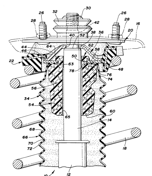
Fig. 1 is a longitudinal sectional view
illustrating a preferred embodiment of the present
jounce bumper and dust shield subassembly mounted
between a strut and an upper mount assembly.

DETAILED DESCRIPTION OF THE PREFERRED EMBODIMENT


A conventional strut is indicated generally
at 10 in Fig. 1 and includes a reservoir tube 12
mounting a reciprocable piston rod 14. The strut 10 is
mounted between a wheel assembly (not illustrated) and
a vehicular body 16 and undergoes compression and
rebound as it dissipates energy from a spring 18 in a
well-known manner.


2~76~9~


An upper mount assembly 20 is provided to
mount the strut 10 to the body 16. The upper end of
the spring 18 is seated on an isolator 22, preferably
having an elastomeric covering. A bearing set (not
illustrated) is provided between the isolator 22 and
the upper mount assembly 20. The as~embly 20 includes
upwardly projecting threaded fasteners 26 which receive
nuts 28 to retain the assembly 20 on the body 16. The
piston rod 14 projects upwardly through the isolator 22
and the upper mount assembly 20 and is retained by a
nut 30 threaded against an upper rate washer 32.
A jounce bumper and dust shield ~ubassembly
34 according to the present invention is provided
between the strut 10 and the isolator 22. The
subassembly 34 includes a washer cup 36 having a top
planar surface 38 and an annular opening 40 for
receiving a reduced-diameter portion 42 of the pi~ton
rod 14. A radially-expanding side wall 44 projects
downwardly from the top planar surface 38 and
terminates in a flange portion 46. A planar washer 48
having an annular opening 50 larger than opening 40 is
secured to the flange 46 by any suitable means, e.g.,
welding. When installed on the piston rod 14, the top
planar surface 38 rests against a shoulder 52 in the
piston rod 14 to seat the washer cup 36 and washer 48
with respect to the piston rod 14.
A jounce bumper 54 is a tubular member formed
from an elastomeric material. The jounce bumper 54
includes a generally cylindrical body 56 and generally
planar top and bottom end surfaces 58,60. A resilient
collar 62 is preferably integrally formed with the top
surface 58. The diameter of the preferably annular
collar 62 is sized so that its undeformed ~tate is


2076~9~


greater than the diameter of opening 50 and it is
capable of elastically deforming as it passes through
the opening 50 in the washer 48 and then expanding to
its approximate original size after it passes through
the opening 50. Preferably, a groove 63 is provided in
the outer surface of the collar 62 for receiving the
washer 48. A cam surface 64 enhances the insertion of
the collar 62 through the opening 50. An axial bore 65
is provided through the body 56 and collar 62 for
receiving the piston rod 14.
A dust shield 66 is a tubular member
preferably formed from an elastomeric material. A dust
shield suitable for use with the present subassembly 34
is disclosed in U.S. Patent 4,969,542, "Dust Shield for
a Damper, n issued November 13, 1990.
The dust shield 66 includes a hollow
cylindrical body 68 having a plurality of inner and
outer convolutions 70,72. The diameter of the body 68
is sized greater than the diameter of the jounce bumper
54 so that the dust shield 66 covers and does not
interfere with the jounce bumper 54 when mounted on the
piston rod 14. An upper end of the dust shield 66
includes a conical portion 74 having an upper planar
surface 76. An annular opening 78 is provided in the
upper planar surface 76 of sufficient size to receive
the piston rod 14.
To assemble the subassembly 34, the upper
planar surface 76 of the dust shield 66 is placed in
contact with a lower surface of the washer 48 so that
respective openings 78,50 are aligned. The jounce
bumper 54 is inserted from a lower end of the dust
shield 66 through the body 68 until the collar 62

-A

- 2076497


passes through the opening 50 and expands radially
outwardly so that the collar 62 rests on an upper
surface of the washer 48. The groove 63 seats the
washer 48. After the collar 62 is inserted through the
opening 50, the dust shield 66 is trapped between the
jounce bumper 54 and the washer 48, eliminating the
need for fasteners, bonding agents or other means used
in the prior art.
The subassembly 34 is easily and quickly
inserted over the piston rod 14 prior to the
installation of the strut 10. As the suba~sembly 34 is
fitted, the piston rod 14 is received through the axial
bore 65 and the opening 40 of the waeher cup 36. As
described above, the piston rod 14 is retained to the
upper mount assembly 20 by the nut 30.
Although the present invention has been
described with reference to a preferred embodiment,
workers skilled in the art will recognize that changes
may be made in form and detail without departing from
the spirit and scope of the invention. The relative
terms used in this description like "upper," "lower,"
"top," and~bottom" are used for ease of reference and
are not intended to unduly limit the ~cope of the
invention.


Representative Drawing
A single figure which represents the drawing illustrating the invention.
Administrative Status

For a clearer understanding of the status of the application/patent presented on this page, the site Disclaimer , as well as the definitions for Patent , Administrative Status , Maintenance Fee  and Payment History  should be consulted.

Administrative Status

Title Date
Forecasted Issue Date 1996-04-30
(22) Filed 1992-08-20
(41) Open to Public Inspection 1993-04-24
Examination Requested 1994-03-16
(45) Issued 1996-04-30
Deemed Expired 2002-08-20

Abandonment History

There is no abandonment history.

Payment History

Fee Type Anniversary Year Due Date Amount Paid Paid Date
Application Fee $0.00 1992-08-20
Maintenance Fee - Application - New Act 2 1994-08-22 $100.00 1994-08-05
Registration of a document - section 124 $0.00 1994-11-15
Maintenance Fee - Application - New Act 3 1995-08-21 $100.00 1995-08-04
Maintenance Fee - Patent - New Act 4 1996-08-20 $100.00 1996-08-06
Maintenance Fee - Patent - New Act 5 1997-08-20 $150.00 1997-08-06
Maintenance Fee - Patent - New Act 6 1998-08-20 $150.00 1998-08-06
Maintenance Fee - Patent - New Act 7 1999-08-20 $150.00 1999-08-06
Maintenance Fee - Patent - New Act 8 2000-08-21 $150.00 2000-08-04
Owners on Record

Note: Records showing the ownership history in alphabetical order.

Current Owners on Record
SATURN CORPORATION
GENERAL MOTORS CORPORATION
Past Owners on Record
KELLER, CHRIS FRED, JR.
LE BLANC, RAYMOND FRANCIS
PINCH, WILLIAM DEWITT
Past Owners that do not appear in the "Owners on Record" listing will appear in other documentation within the application.
Documents

To view selected files, please enter reCAPTCHA code :


To view images, click a link in the Document Description column. To download the documents, select one or more checkboxes in the first column and then click the "Download Selected in PDF format (Zip Archive)" or the "Download Selected as Single PDF" button.

List of published and non-published patent-specific documents on the CPD .

If you have any difficulty accessing content, you can call the Client Service Centre at 1-866-997-1936 or send them an e-mail at CIPO Client Service Centre.


Document
Description 
Date
(yyyy-mm-dd) 
Number of pages   Size of Image (KB) 
Representative Drawing 1999-03-12 1 43
Drawings 1993-11-13 1 73
Description 1993-11-13 6 274
Cover Page 1996-04-30 1 21
Abstract 1996-04-30 1 24
Description 1996-04-30 6 214
Claims 1996-04-30 3 81
Drawings 1996-04-30 1 45
Cover Page 1993-11-13 1 22
Abstract 1993-11-13 1 32
Claims 1993-11-13 6 248
Fees 1999-08-06 1 29
Fees 1998-08-06 1 36
Fees 1997-08-06 1 34
Fees 2000-08-04 1 29
Prosecution Correspondence 1995-07-25 2 60
Examiner Requisition 1995-02-10 2 57
Prosecution Correspondence 1994-03-16 3 135
Examiner Requisition 1993-11-18 2 70
Office Letter 1993-03-19 1 47
Office Letter 1993-04-16 1 55
PCT Correspondence 1993-07-22 3 103
Office Letter 1993-09-09 1 20
PCT Correspondence 1996-02-20 1 34
Fees 1995-08-04 1 48
Fees 1996-08-06 1 40
Fees 1994-08-05 1 52