Language selection

Search

Patent 2076813 Summary

Third-party information liability

Some of the information on this Web page has been provided by external sources. The Government of Canada is not responsible for the accuracy, reliability or currency of the information supplied by external sources. Users wishing to rely upon this information should consult directly with the source of the information. Content provided by external sources is not subject to official languages, privacy and accessibility requirements.

Claims and Abstract availability

Any discrepancies in the text and image of the Claims and Abstract are due to differing posting times. Text of the Claims and Abstract are posted:

  • At the time the application is open to public inspection;
  • At the time of issue of the patent (grant).
(12) Patent: (11) CA 2076813
(54) English Title: END CAP APPLICATORS FOR HIGH FREQUENCY ELECTRODELESS LAMPS
(54) French Title: ELECTRODES D'EMBOUT POUR LAMPES SANS ELECTRODE A HAUTE FREQUENCE
Status: Deemed expired
Bibliographic Data
(51) International Patent Classification (IPC):
  • H05B 41/24 (2006.01)
  • H01J 61/06 (2006.01)
  • H01J 65/04 (2006.01)
  • H05B 41/02 (2006.01)
(72) Inventors :
  • LAPATOVICH, WALTER P. (United States of America)
  • BUTLER, SCOTT J. (United States of America)
  • BOCHINSKI, JASON R. (United States of America)
(73) Owners :
  • GTE PRODUCTS CORPORATION (United States of America)
(71) Applicants :
  • GTE PRODUCTS CORPORATION (United States of America)
(74) Agent: R. WILLIAM WRAY & ASSOCIATES
(74) Associate agent:
(45) Issued: 2005-07-12
(22) Filed Date: 1992-08-25
(41) Open to Public Inspection: 1993-03-11
Examination requested: 1999-08-25
Availability of licence: N/A
(25) Language of filing: English

Patent Cooperation Treaty (PCT): No

(30) Application Priority Data:
Application No. Country/Territory Date
07/757,095 United States of America 1991-09-10

Abstracts

English Abstract


A high frequency applicator for energizing electrode-less
lamps is described. The applicators are end cups
electrically attached to the ends of phased feed points of
a planar transmission line, and facing each other so as to
form a gap between the end cups. The end cups each have a
concave surface facing the gap which forces an electric
field concentration in the vicinity of the end cups and in
the gap between the opposing end cups. Such a field
configuration is useful for energizing a lamp capsule
placed within the gaps formed by the end cups. The end
cups can be made of metal or metallized ceramic.


Claims

Note: Claims are shown in the official language in which they were submitted.


-6-


THE EMBODIMENTS OF THE INVENTION FOR WHICH AN EXCLUSIVE PROPERTY
OR PRIVILEGE IS CLAIMED ARE DEFINED AS FOLLOWS:

1. A coupling system for delivering microwave power
to a lamp capsule comprising:
a first end cup receiving microwave power at a first
end and having a second end having a concave conductive
surface facing a gap; and
a second end cup receiving microwave power at a first
end positioned coaxial with the first end cup and having a
second end having a concave conductive surface facing the
gap to contain a lamp capsule and facing the concave surface
of said first end cup wherein the first end cup and the
second end cup are electrically coupled to be 180° out of
phase in delivering power to the lamp capsule,
wherein the concave surfaces surround but do not touch
end chambers of said lamp capsule, and the separations
between the surfaces and the lamp capsule are approximately
0.1 to 10 mm.

2. The coupling system according to claim 1 wherein
said first end cup and said second end cup are supplied by
a single microwave power source, through a microwave
transmission line and the input of the first end cup is
separated from the input of the second end cup by an
electrical connection comprising a balun impedance
transformer.

3. The coupling system according to claim 1 wherein
the first end cup and the second end cup are supplied by a
single microwave power source, and the input to the first
end cup is separated from the input to the second end cup
by a microstrip line.

4. The coupling system according to claim 1 wherein
the first end cup and the second end cup are supported by
an insulative card having a microstrip line formed on a
first side and a ground surface formed on an opposite side.


-7-

5. The coupling system according to claim 1 wherein
the concave surfaces of the first and second end cups
allows electric field shaping in the vicinity of the
surface resulting in a field enhancement of about 2.7.
6. The coupling system according to claim 1 wherein
the first and second end cups are made from a solid metal.
7. The coupling system according to claim 1 wherein
the end cups are made from a dielectric and the concave
surfaces are made of metal.
8. The coupling system according to claim 1 wherein
the concave surfaces are made from a high temperature
superconductor.
9. The coupling system according to claim 1 wherein
the conductive surfaces of the first and second end cups
have central aperatures in which supporting means for a
lamp capsule can be placed therethrough.
10. A microwave powered lamp comprising:
a first end cup receiving input microwave power at a
first end and having a second end comprising a concave
conductive surface facing a gap:
a second end cup position coaxial with the first end
cup and receiving input power at a first end and having a
second end comprising a concave conductive surface facing the
gap and facing the concave surface of the first end cup;
a lamp capsule positioned in the gap and whose end
chambers are separated from the concave surfaces of the first
and second end cup by a distance of approximately 0.1 mm to 10
mm.


-8-

11. The lamp according to claim 10 wherein end cups
are made of metal.
12. The lamp according to claim 10 wherein the end
cups are made from a dielectric and the surfaces are made
of metal.
13. The lamp according to claim 10 wherein the concave
surfaces are made from a high temperature superconductor.
14. The lamp according to claim 10 wherein the first
and second end cups are electrically coupled to be 180° out
of phase.

Description

Note: Descriptions are shown in the official language in which they were submitted.


~~'~~~13
91-3-089 CN -1-
END CUP APPLICATORS FOR_HIGH_ERE-QUENCY
ELECTRODELESS LAMPS
The present invention relates to a high frequency
applicator for energizing electrodeless lamps. More
specifically, metallized ceramic or metal blocks facing
each other to form a gap are shaped so as to force an
electric field concentration in the gap between the blocks
thereby providing an RF application system for elecarode-
less lamps.
Cup like termination fi.xt ores for energizing elec-
trodeless lamps are depicted by McNeill in U.S. 4,041,352
which shows single ended excitation, and in U.S. 4,266,162
which discloses double ended excitation. The more rele-
vant patent is '162 in which McNeill is concerned with
elongated sources, and in which he recites the virtues of
double ended excitation (see col. 7, lines 54-68). While
the pictures show cup-like termination fixtures as the
applicator of power to the lamps, they axe not described
in detail. In claim 1, McNeill. cites the termination load
approach, and in claim 5 McNeill cites the need to control
the electric field in the vicinity of the lamp envelope.
In addition, McNeill '162 requires an outer conductor
disposed around the coupling fixtures.
Applicators for energizing electrodeless discharges
using planar transmission lines and helical couplers are
described by Lapatovich in U.S. Patent No. 5,070,277. In
this reference slow wave applicators made from helical
coils are described.
The present invention relates to a novel applicator
for energizing an electrodeless lamp.
Accordingly, the present invention provides a
coupling system for delivering microwave power to lamp
capsule comprising: a first end cup receiving microwave
power at a first end and having a second end having a


20'~6~1~
91-3-089 CN -2-
concave conductive surface faring a gap; and a second end
cup receiving microwave power at a first end positioned
coaxial with 'the first end cup and having a second end
having a concave conductive surface facing the gap to
contain a lamp capsule and facing the concave surface of
said first end cup wherein the first end cup and the
second end cup are electrically coupled to be 180° out of
phase in delivering power to the lamp capsule.
The coupling system performs best when the two end
cups are supplied by an electrical connection which
constitutes a balun impedance transformer between the lamp
capsule and the microwave power source and the transmis-
sion line delivery power to the coupling system.
Some embodiments of the invention will now be
described, by way of example, with reference to the
accompanying drawings in which:
Figure 1 shows three views of the end cup applicators
of one embodiment of the present invention.
Figure 2 shows a lamp capsule positioned between the
end cup applicators of one embodiment of the present
invention.
Figure 3 shows three views of an alternate end cup
applicator of one embodiment of the present invention.
For a better understanding of the present invention,
together with other and further objects, advantages and
capabilities thereof, reference is made to the following
detailed description and appended claims in connection
with the preceding drawings and description of some
aspects of the invention.
A high frequency applicator fox energizing electrode-
less lamps is described. The applicators are formed from
two blocks of material electrically attached to the ends
of phased feed points of a planar transmission line and
facing one another so as to make a gap between the blocks.


20~6~13
91-3-089 CN -3-
The blocks of material may be metal or metallized ceramic.
The shaping of the faces of the blocks .forces an electric
field concentration in the vicinity of the bloc)c and in
the gap between opposing blocks. Such a field configura-
tion is desirable for energizing an electrodeless dis-
charge in a capsule placed within the gap formed by the
opposing blocks. The shaping is contoured to produce an
electric field enhancement away .from the surface of block
so as to be coincident with the internal volume of a gas
lOdischarge lamp placed within the gap to cause excitation
of the gas therein to a radiating state.
Further description of an applicator according to the
present invention is by way of reference to the enclosed
drawings. Figure 1 shows three views of a solid metal end
cup :field enhancing applicator. The metal used in the
tests was copper plated with nickel, and then a layer of
gold. The small central hole is used to pass the
mechanical support (i.e. a small quartz tube) for the lamp
20capsule. While this is the preferred embodiment, it
should be obvious to one skilled in the art that the
"blocks" need not be rectangular parallelpipeds. Only the
concave surfaces facing the gap are responsible for the
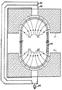
electric field enhancement. Fig. 2 shows a cross
sectional view of the lamp capsule 20 positioned within
the gap formed by facing metallic end cups 21 the electric
field lines 22 generated by the device. The lamp capsule
is not in contact with the end cups at any point. The
field lines 22 density is a measure of the electric field
30strength and increases along tYze axis of the lamp capsule
locally near the end cup applicator. A quasistatic
analysis of the axial electric field shows an axial
electric field enhancement of about 2.7 times greater than
the field generated between plane parallel metallic
blocks.


91-3-089 CN -4-
As shown, a microwave power source 25 supplies power
to both the first and second end cups via a microstrip
transmission line 2.3. Preferably, the transmission line
is a balun impedance transformer. The first and second
end cups axe supported by an insulative card 24 having
microstrip line 23 formed on one side and a ground surface
formed on the opposite side.
Fig. 3 shows an alternative design for end cups
applicators using metallized ceramic blocks. In the
l0example, titanium-tungsten-gold was applied to machined
Macor (Trade Mark). Other materials from which the blocks
can be fabricated include quartz, alumina, beryllia and
high temperature plastics. The advantage of this
technique is the reduced thermal conductivity of the end
cup so formed. Additionally, the reduction of the sheer
metal mass .reduces the stray capacitance of the end cup
with nearby metallic surfaces making the applicator easier
to tune to the lamp operating impedance. The metalliza-
tion as depicted allows for soldering to the planar
20transmission line and for the field shaping via the
concave surface. Again, it should be obvious to one
skilled in the art that the ceramic piece serves only as a
support for the concave metallic surface, and that other
geometries may be used other than rectangular para11e1-
pipeds.
The curvature of the end cups is designed to approx-
imate the curvature of the lamp end chambers as shown in
Fig. 2. The radius of curvature of the end cups is in the
range of 0.1 to 10 mm larger than the radius of the tamp
30 end chambers with the preferred differential. of 0.5 mm for
lamps operating at approximately 25 W. Consequently, the
end cups of the lamp do not contact the lamp at any point.
Both metallic and metallized ceramic types were tested on
microstripli.ne at 915 MHz and 2.45 GHz. Th.e lamps in both
cases operated similarly to helically excited lamps as
described in U.S. Patent No. 5,070,277. It is apparent


2Q~~~13
91-3-089 CN -5-
that these end cup applicators may be used at frequencies
other than the two cited above.
The lamp capsule used in the present disclosure were
made of quartz and had an outer diameter o.f 3 mm and an
inner diameter of 2 mm. The capsules had an internal
length of approximately 10 mm. Flowever, lamps of other
dimensions are easily powered by the applicators of the
present invention.
The lamp capsule encloses a lamp fill that may
l0include various additional doping materials as are known
in the art. The lamp fill composition is chosen to
inr.lude at least one material that i.s vaporizable and
excitable by radio frequency power. The lamp fill. compo-
sitions useful in the present invention are those familiar
in arc discharge tubes. The preferred gas is a Penning
mix of largely neon with a small amount (<1%) of argon
although xenon, kryptron, argon or pure neon may be used.
The lamp fill includes a metallic compound such as a salt
like scandium iodide. The lamp fill used is approximately
200.3 milligram of mercury, 0.1 milligram of sodium-scandium
iodide with a Penning gas mixture at about twenty torr.
The Penning gas mixture consisted of approximated 0.005%
argon in neon.
The end cup design lends itself to mass production
easier than the helical coils. Autcmated machinery can
handle the small rectangular parallelpipeds easier than
the helical coils with less chance of entangling.
While there has been shown and described what are at
present considered the preferred embodiments of the
30present invention, it will be obvious to those skilled in
the art that various changes, alterations and modifica-
tions may be made therein without departing from the scope
of the invention as defined by the appended claims.

Representative Drawing
A single figure which represents the drawing illustrating the invention.
Administrative Status

For a clearer understanding of the status of the application/patent presented on this page, the site Disclaimer , as well as the definitions for Patent , Administrative Status , Maintenance Fee  and Payment History  should be consulted.

Administrative Status

Title Date
Forecasted Issue Date 2005-07-12
(22) Filed 1992-08-25
(41) Open to Public Inspection 1993-03-11
Examination Requested 1999-08-25
(45) Issued 2005-07-12
Deemed Expired 2008-08-25

Abandonment History

There is no abandonment history.

Payment History

Fee Type Anniversary Year Due Date Amount Paid Paid Date
Application Fee $0.00 1992-08-25
Registration of a document - section 124 $0.00 1993-03-19
Maintenance Fee - Application - New Act 2 1994-08-25 $100.00 1994-08-03
Maintenance Fee - Application - New Act 3 1995-08-25 $100.00 1995-08-16
Maintenance Fee - Application - New Act 4 1996-08-26 $100.00 1996-07-31
Maintenance Fee - Application - New Act 5 1997-08-25 $150.00 1997-08-20
Maintenance Fee - Application - New Act 6 1998-08-25 $150.00 1998-08-24
Maintenance Fee - Application - New Act 7 1999-08-25 $150.00 1999-08-03
Request for Examination $400.00 1999-08-25
Maintenance Fee - Application - New Act 8 2000-08-25 $150.00 2000-08-21
Maintenance Fee - Application - New Act 9 2001-08-27 $150.00 2001-08-13
Maintenance Fee - Application - New Act 10 2002-08-26 $200.00 2002-08-19
Maintenance Fee - Application - New Act 11 2003-08-25 $200.00 2003-08-25
Maintenance Fee - Application - New Act 12 2004-08-25 $250.00 2004-08-23
Final Fee $300.00 2005-04-27
Maintenance Fee - Patent - New Act 13 2005-08-25 $250.00 2005-08-03
Maintenance Fee - Patent - New Act 14 2006-08-25 $250.00 2006-07-14
Owners on Record

Note: Records showing the ownership history in alphabetical order.

Current Owners on Record
GTE PRODUCTS CORPORATION
Past Owners on Record
BOCHINSKI, JASON R.
BUTLER, SCOTT J.
LAPATOVICH, WALTER P.
Past Owners that do not appear in the "Owners on Record" listing will appear in other documentation within the application.
Documents

To view selected files, please enter reCAPTCHA code :


To view images, click a link in the Document Description column. To download the documents, select one or more checkboxes in the first column and then click the "Download Selected in PDF format (Zip Archive)" or the "Download Selected as Single PDF" button.

List of published and non-published patent-specific documents on the CPD .

If you have any difficulty accessing content, you can call the Client Service Centre at 1-866-997-1936 or send them an e-mail at CIPO Client Service Centre.


Document
Description 
Date
(yyyy-mm-dd) 
Number of pages   Size of Image (KB) 
Representative Drawing 1998-10-23 1 3
Claims 2003-04-07 3 101
Abstract 1993-12-21 1 18
Cover Page 1993-12-21 1 16
Claims 1993-12-21 4 120
Representative Drawing 2004-10-04 1 16
Drawings 1993-12-21 3 59
Description 1993-12-21 5 216
Drawings 2002-06-05 3 71
Claims 2002-06-05 3 94
Claims 2004-05-10 3 90
Cover Page 2005-06-16 1 46
Prosecution-Amendment 2004-02-04 1 29
Correspondence 2005-04-27 1 31
Fees 2004-08-23 1 31
Fees 2000-08-21 1 34
Assignment 1992-08-25 5 202
Prosecution-Amendment 1999-08-25 1 45
Prosecution-Amendment 2001-12-19 2 59
Prosecution-Amendment 2002-06-05 5 150
Prosecution-Amendment 2002-10-30 2 64
Prosecution-Amendment 2003-04-07 3 82
Fees 2003-08-25 1 31
Prosecution-Amendment 2003-10-15 2 64
Correspondence 2003-12-02 1 12
Fees 2002-08-19 1 39
Fees 2001-08-13 1 42
Fees 1999-08-03 1 36
Prosecution-Amendment 2004-05-10 4 77
Fees 1996-07-31 1 50
Fees 1995-08-16 2 68
Fees 1994-08-03 1 52