Language selection

Search

Patent 2076820 Summary

Third-party information liability

Some of the information on this Web page has been provided by external sources. The Government of Canada is not responsible for the accuracy, reliability or currency of the information supplied by external sources. Users wishing to rely upon this information should consult directly with the source of the information. Content provided by external sources is not subject to official languages, privacy and accessibility requirements.

Claims and Abstract availability

Any discrepancies in the text and image of the Claims and Abstract are due to differing posting times. Text of the Claims and Abstract are posted:

  • At the time the application is open to public inspection;
  • At the time of issue of the patent (grant).
(12) Patent: (11) CA 2076820
(54) English Title: APPARATUS FOR RESHAPING METAL PANELS OF AUTOMOBILES OR MOTOR VEHICLES OR THE LIKE
(54) French Title: MACHINE POUR REPROFILER DES PANNEAUX DE METAL ET AUTRES ELEMENTS SEMBLABLES UTILISES DANS LA CONSTRUCTION DE VEHICULES AUTOMOBILES
Status: Deemed expired
Bibliographic Data
(51) International Patent Classification (IPC):
  • B21D 11/20 (2006.01)
  • B21D 1/06 (2006.01)
(72) Inventors :
  • HORAN, GERALD PATRICK (Canada)
(73) Owners :
  • CHASSIS LINER CORPORATION (United States of America)
(71) Applicants :
(74) Agent: ROLSTON, GEORGE A.
(74) Associate agent:
(45) Issued: 1995-10-10
(22) Filed Date: 1992-08-27
(41) Open to Public Inspection: 1994-02-28
Examination requested: 1992-08-27
Availability of licence: N/A
(25) Language of filing: English

Patent Cooperation Treaty (PCT): No

(30) Application Priority Data: None

Abstracts

English Abstract


An apparatus for reshaping metal panels or the like of motor
vehicles or automobiles, the apparatus comprising;
a first internally threaded circular in perimeter nut, having two
ends whereon one end thereof there is located a multiplicity of substantially
circular grooves radially extending outward to the perimeter of said nut to grasp
one side of a metal panel in use,
a second internally threaded circular in perimeter nut, having two
ends whereon one end thereof there is located a multiplicity of substantially
circular grooves radially extending outward to the perimeter of said nut
complimentary to said grooves radially extending outward to the perimeter of
the first nut, to grasp another side of a metal panel in use,
a hollow externally threaded shaft, having two ends, to receive the
first and second nut, said hollow portion of said shaft to receive pulling means to
be applied to said apparatus and to allow said nuts to rotate with said shaft about
said pulling means in use,
and two metal fingers projecting from at least one nut end distant
said end having said circular grooves thereon for aiding a user in tightening and
loosening said nut on said threaded shaft,wherein the substantially circular nutreduces the imbalance of forces applied to said metal when a pulling force is
applied thereto, decreasing the possibility of tearing or damaging the metal panel
during reshaping.


Claims

Note: Claims are shown in the official language in which they were submitted.


THE EMBODIMENTS OF THE INVENTION IN WHICH AN EXCLUSIVE
PROPERTY OR PRIVILEGE IS CLAIMED ARE AS FOLLOWS:

1. An apparatus for reshaping metal panels or the like of motor
vehicles or automobiles, the apparatus comprising:
a first internally threaded nut, whose shape is substantially circular
in perimeter and has two ends, where on one end thereof there is located
grasping means to grasp one side of the metal panel or the like,
a second internally threaded nut, whose shape is substantially
circular in perimeter and has two ends, where on one end thereof there is located
grasping means complimentary to said grasping means of said first nut to grasp
another side of the metal panel or the like,
a externally threaded shaft, having two ends, to receive the first and
second nut such that the end of each nut where there is located grasping means
is located adjacent the one side and the another side of the metal panel when inuse, and
receiving means on said threaded shaft for receiving pulling means
to be applied to said apparatus when in use, such that when the apparatus is in
use, the substantially circular in perimeter nuts when a pulling force is applied
thereto reduces the imbalance of forces applied to said panel, decreasing the
possibility of tearing or damaging the panel during reshaping.

2. The apparatus of claim 1 where said receiving means allow said
nuts to rotate with said shaft about said pulling means in use.

3. The apparatus of claim 1 where said grasping means comprise a
multiplicity of circular grooves radially extending outward to the perimeter of
said nut.

4. The apparatus of claim 1 wherein said receiving means comprises a

-8-
hollow bore through said threaded shaft.
5. The apparatus of claim 1 wherein at least one of said nuts further
comprise integral detent means on one end thereof distant said end with
grasping means thereon, to aid a user in tightening and loosening at least one of
said nuts onto said shaft.

6. The apparatus of claim 5 wherein said detent means comprises at
least one finger projecting from said nut.

7. An apparatus for reshaping metal panels or the like of automobiles
or motor vehicles or the like, the apparatus comprising;
a first internally threaded circular in perimeter nut, having two
ends whereon one end thereof there is located a multiplicity of substantially
circular grooves radially extending outward to the perimeter of said nut to grasp
one side of a metal panel in use,
a second internally threaded circular in perimeter nut, having two
ends whereon one end thereof there is located a multiplicity of substantially
circular grooves radially extending outward to the perimeter of said nut
complimentary to said grooves radially extending outward to the perimeter of
the first nut, to grasp another side of a metal panel in use,
a hollow externally threaded shaft, having two ends, to receive the
first and second nut, said hollow portion of said shaft to receive pulling means to
be applied to said apparatus and to allow said nuts to rotate with said shaft about
said pulling means in use,
and two metal fingers projecting from at least one nut end distant
said end having said circular grooves thereon for aiding a user in tightening and
loosening said nut on said threaded shaft,wherein the substantially circular nutreduces the imbalance of forces applied to said metal when a pulling force is
applied thereto, decreasing the possibility of tearing or damaging the metal panel
during reshaping.

Description

Note: Descriptions are shown in the official language in which they were submitted.


207682~
-


TITLE OF INVENTION
Apparatus for reshaping metal panels of automobiles or motor
vehicles or the like.
LD OF INVENTION
This invention relates to the reshaping of metal panels or the like
incorporating an apparatus which reduces the possibility of tearing or damaging
the metal panel upon reshaping thereof.
BACKGROUND OF THE INVENTION
In the field of collision damage repair to motor vehicles or the like,
the current methods and apparatuses used to repair damaged metal panels
commonly are clamps having square-like edges that are secured on an edge of
the damaged panel, and then a pulling force is applied to straighten out the panel
to its original shape. We have found that these edge clamps, the square corners
thereof, have a tendency to concentrate the pulling load at the corners of the
clamp, causing the metal panel to be damaged, specifically tearing near the
square-like corner of the clamp, due to the weakening of the panel near the
square-like corner of the clamp.
Furthermore, in the event that there is more damage to one side of
the clamp than the other side of the clamp, the pulling forces become unbAlAnce(1
and tend to concentrate the pulling forces on the side of the clamp that has
already straightened out the panel and therefore causing the metal panel to failand thus tear.
It is therefore an object of the invention to provide a means to
reshape metal panels or the like reducing the possibility of dArnAging or tearing
of the panel when being pulled.
It is another object of the invention to provide a means to reshape
metal panels or the like which reduces the imbalance of forces on a damaged
metal panel when being reshaped to its original shape.
Further objects of the invention will become apparent from a

-2- 20~6820

-
consideration of the following description.
SUMMARY OF THE INVENTION
In one embodiment of the invention there is provided an
apparatus for reshaping metal panels or the like preferably motor vehicle metal
5 panels, the apparatus comprising;
a first internally threaded nut, whose shape is substantially circular
in perimeter and has two ends, where on one end thereof there is located
grasping means to grasp one side of the metal panel or the like,
a second internally threaded nut, whose shape is substAntiAlly
10 circular in perimeter and has two ends, where on one end thereof there is located
grasping means complimentary to said grasping means of said ffrst nut to grasp
another side of the metal panel or the like,
a externally threaded shaft, having two ends, to receive the first and
second nut such that the end of each nut where there is located grasping means
15 is located adjacent the one side and the another side of the metal panel when in
use, and
receiving means on said threaded shaft, preferably a hollow bore
through said threaded shaft, for receiving pulling means to be applied to said
apparatus when in use and preferably said receiving means allow said nuts to
20 rotate with said shaft about said pulling means in use, such that when the
apparatus is in use, the substantially circular in perimeter nuts when a pullingforce is applied thereto reduces the imbalance of forces applied to said panel,
decreasing the possibility of tearing or damaging the panel during reshaping.
In a preferred embodiment said grasping means comprise a
25 multiplicity of circular grooves radially extending outward to the perimeter of
each of said nuts.
In a further embodiment of the invention, at least one of said nuts
further comprise integral detent means on one end thereof distant said end with
grasping means thereon preferably at least one finger projecting from at least one

-3-
- ~76820
of said nuts, to aid a user in tightening and loosening at least one of said nuts
onto said shaft.
In yet another preferred embodiment of the invention, there is
provided an apparatus for reshaping metal panels or the like preferably motor
5 vehicle metal panels, the apparatus comprising;
a first internally threaded circular in perimeter nut, having two
ends whereon one end thereof there is located a multiplicity of substAntiAlly
circular grooves radially exten~1ing outward to the perimeter of said nut to grasp
one side of a metal panel in use,
a second internally threaded circular in perimeter nut, having two
ends whereon one end thereof there is located a multiplicity of substantially
circular grooves radially extending outward to the perimeter of said nut
complimentary to said grooves radially extending outward to the perimeter of
the first nut, to grasp another side of a metal panel in use,
a hollow externally threaded shaft, having two ends, to receive the
first and second nut, said hollow portion of said shaft to receive pulling means to
be applied to said apparatus and to allow said nuts to rotate with said shaft about
said pulling means in use,
and two metal fingers projecting from at least one nut end distant
said end having said circular grooves thereon for aiding a user in tightening and
loosening said nut on said threaded shaft,wherein the substantially circular nutreduces the imbalance of forces applied to said metal when a pulling force is
applied thereto, decreasing the possibility of tearing or damaging the metal panel
during reshaping.
Further objects and embodiments of the invention will become
apparent from reading the following detailed description of the invention in a
preferred embodiment.

4 ~)76$20
.
BRIEF DESCRIPTION OF THE DRAWINGS
The invention will now be illustrated with respect to the following
drawings illustrating embodiments of the invention in which:
Figure 1 is an exploded view of the invention in a preferred
5 embodiment.
Figure 2 is an exploded view of the invention in a preferred
embodiment when being inserted on to a metal panel.
Figure 3 is a side cross sectional view of the invention in a prer~lled
embodiment.
Figure 4 is a perspective view of the invention in a preferred
embodiment.
Figures 5 is a perspective view of the invention in a preferred
embodiment.
Figure 6 is a plan view of the invention showing the rotation
15 capability of the invention with the pulling device.

DETAILED DESCRIPTION OF PREFERRED EMBODIMENTS OF T H E
INVENTION
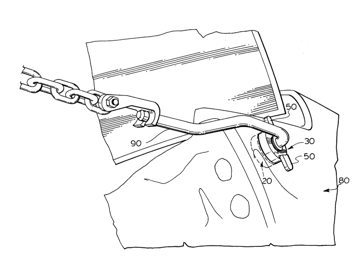
Referring now to the Figures, the invention is generally denoted as
20 10 having a first substantially circular nut 20 and a second substantially circular
nut 30, joined to each other by a hollow shaft 40. The material of manufacture of
the invention 10 is a suitable metal or metal alloy or the like which can
withstand excessive pulling forces thereon. The nut 20 has two ends 21,22 and a
side 23. it also has a threaded bore 24. On end 21, there is seen a series of circular
25 grooves 25 radially extending outwards from the surface near the bore 24
proximate the side 23 of the nut 20. Similarly, nut 30 has two ends 31,32 and a
side 33, and also a threaded bore 34 extending from one end 31 to the other end
32. On the surface of end 31, there are a series of circular grooves 35 radiallyextending outwards from the surface end 31 near the bore 34 to proximate the

-5- ~76~

side 33 of the nut 30. The circular grooves 25 on the nut 20 are complementary to
the circular grooves 35 on the nut 30, in order to grasp the metal panel when
applying a pulling force thereto. The nut 30, also has on end 32 two fingers 36 to
aid a user in tightening or loosening the nut 30 onto the threaded shaft 40. The5 threaded shaft 40 in the preferred embodiment has a bore 41 running the lengthof the shaft 40. the bore 41 is used to receive a pulling device to exert a pulling
force on the invention 10 when in use, and to allow the nuts 20 and 30 to rotatewith the shaft 40 if the pulling force direction is needed to be changed or if there
is an imbalance of forces on the metal panel when a pulling force is applied
10 thereto.
In use, the user would thread on one nut onto one end of the
threaded shaft 40 as best seen in figure 2. The user would then proceed to insert
the threaded shaft 40 having the first nut threaded thereon, through a hole
(existing or made for this purpose) near the damaged area of an automobile or
15 motor vehicle metal panel 80. The user would then thread a second nut onto
the threaded shaft 40 such that the metal panel 80 would be sandwiched by the
nut end 21 of nut 20 having a series of circular grooves 35 thereon and the nut
end 31 of the nut 30 having a series of complementary circular grooves 45 to thegrooves 35, and then tighten the nut 30 by using the fingers 50 thus securely
20 grasping the panel 80 between the two nuts 20 and 30 as best seen in figure 3. The
user would then insert a pulling device, in this case a finger hook 90 as best seen
in figures 1 and 4, in through the bore 41 of the shaft 40 held in place by a nut 91,
such that the finger hook 90 is free to rotate about said invention 10 as best seen
in figure 6. The user would then apply a pulling force on the finger hook 90,
25 which in turn pulls the invention 10 substantially along the plane of the metal
panel 80, causing the metal panel to straighten out to its original form.
Furthermore, as best seen in figure 5, a front pulling shaft bar 100 is insertedthrough the shaft bore 41 to apply a pully force substantially normal to the plane
of the metal panel 80. The circular nuts 20 and 30 while grasping the panel 80,

-6- ~7~l~2~

reduce the chance of tearing or damaging of the panel 80 due to imbalanced
forces on the panel 80 by spreading out the tensile forces on the panel 80 in a
radial movement and not focusing the tensile forces on one particular point on
the metal panel 80 which may cause the panel 80 to tear and be ~lAmA~ed even
5 further. Therefore, since the forces are spread out radially over the length of the
metal panel 80, due to the circular configuration of the nuts 20 and 30, the panel
80 is less likely to tear when undergoing repair (i.e.pulling thereon).
As many changes can be made to the preferred embofiimentc of the
invention without departing from the scope of the invention; it is intended that10 all material contained herein be interpreted as illustrative of the invention and
not in a limiting sense.

Representative Drawing
A single figure which represents the drawing illustrating the invention.
Administrative Status

For a clearer understanding of the status of the application/patent presented on this page, the site Disclaimer , as well as the definitions for Patent , Administrative Status , Maintenance Fee  and Payment History  should be consulted.

Administrative Status

Title Date
Forecasted Issue Date 1995-10-10
(22) Filed 1992-08-27
Examination Requested 1992-08-27
(41) Open to Public Inspection 1994-02-28
(45) Issued 1995-10-10
Deemed Expired 2006-08-28

Abandonment History

There is no abandonment history.

Payment History

Fee Type Anniversary Year Due Date Amount Paid Paid Date
Application Fee $0.00 1992-08-27
Registration of a document - section 124 $0.00 1993-03-19
Maintenance Fee - Application - New Act 2 1994-08-29 $50.00 1994-08-24
Maintenance Fee - Application - New Act 3 1995-08-28 $50.00 1995-08-21
Maintenance Fee - Patent - New Act 4 1996-08-27 $50.00 1996-06-17
Maintenance Fee - Patent - New Act 5 1997-08-27 $75.00 1997-08-25
Maintenance Fee - Patent - New Act 6 1998-08-27 $75.00 1998-08-18
Maintenance Fee - Patent - New Act 7 1999-08-27 $75.00 1999-08-27
Maintenance Fee - Patent - New Act 8 2000-08-28 $75.00 2000-08-25
Registration of a document - section 124 $50.00 2001-06-07
Registration of a document - section 124 $50.00 2001-07-30
Maintenance Fee - Patent - New Act 9 2001-08-27 $75.00 2001-08-27
Registration of a document - section 124 $50.00 2002-04-25
Maintenance Fee - Patent - New Act 10 2002-08-27 $100.00 2002-08-02
Maintenance Fee - Patent - New Act 11 2003-08-27 $200.00 2003-07-14
Maintenance Fee - Patent - New Act 12 2004-08-27 $250.00 2004-07-16
Owners on Record

Note: Records showing the ownership history in alphabetical order.

Current Owners on Record
CHASSIS LINER CORPORATION
Past Owners on Record
3053853 NOVA SCOTIA COMPANY
AUTOCHART COMPANY
CHART INDUSTRIES LTD.
CHARTLINER COMPANY
HORAN, GERALD PATRICK
Past Owners that do not appear in the "Owners on Record" listing will appear in other documentation within the application.
Documents

To view selected files, please enter reCAPTCHA code :


To view images, click a link in the Document Description column. To download the documents, select one or more checkboxes in the first column and then click the "Download Selected in PDF format (Zip Archive)" or the "Download Selected as Single PDF" button.

List of published and non-published patent-specific documents on the CPD .

If you have any difficulty accessing content, you can call the Client Service Centre at 1-866-997-1936 or send them an e-mail at CIPO Client Service Centre.


Document
Description 
Date
(yyyy-mm-dd) 
Number of pages   Size of Image (KB) 
Cover Page 1995-10-10 1 16
Abstract 1995-10-10 1 36
Description 1995-10-10 6 257
Claims 1995-10-10 2 89
Drawings 1995-10-10 4 92
Representative Drawing 1998-08-13 1 25
Fees 1997-08-25 1 59
Fees 2000-08-25 1 49
Correspondence 2001-10-23 1 14
Fees 2001-08-27 1 33
Fees 2003-07-14 1 33
Fees 1999-08-27 1 55
Correspondence 2001-09-27 3 88
Correspondence 2001-08-27 6 143
Assignment 2002-04-25 22 566
Correspondence 2001-10-23 1 15
Fees 1998-08-18 1 60
Fees 2002-08-02 1 35
Correspondence 2002-07-02 1 22
Fees 2004-07-16 1 32
Office Letter 1993-04-16 1 67
Office Letter 1995-08-08 1 65
Office Letter 2001-10-26 2 31
Office Letter 2000-12-12 1 25
Prosecution Correspondence 1995-06-23 9 276
Prosecution Correspondence 1993-05-07 1 30
Fees 1996-06-17 1 74
Fees 1995-08-21 1 78
Fees 1994-08-24 1 71