Note: Descriptions are shown in the official language in which they were submitted.
IMPLANTABLE PLURAL FLUID CAVITY ACCESS PORT
BACKGROUND
l. The Field of the Invention
The present invention relates to a subcutaneously
implantable access port. More specifically, the present
invention relates to an access port having a plurality of
needle-penetrable, self-sealing septums, each affording
repeated access to a corresponding plurality of distinct
fluid cavities each in communication with a plural lumen
catheter.
2. Backqround Art
A variety of implantable devices, known as
subcutaneous access ports, are utilized to deliver fluids
to or to withdraw fluids from the bloodstream of a patient.
Such access ports typically include a needle-
impenetrable housing which encloses one or more fluid
cavities and defines for each such fluid cavity an access
aperture communicating through the housing on the side
thereof which is ad~acent to the skin of the patient when
the access port is implanted in the body thereof.
A needle-penetrable septum is received in and seals
each access aperture. Exit passageways located in an
outlet stem communicate with each of the fluid cavities for
dispensing medication therefrom to a predetermined location
in the body of the patient through an implanted catheter
attached to the access port.
Once the access port and the catheter have been
implanted beneath the skin of a patient, quantities of
medication or blood may be dispensed from one such fluid
cavity by means of a non-coring needle passed through the
skin of the patient and penetrating the septum into one of
the respective fluid cavities. This medication is directed
-2- ~7~3~
in the distal end of the catheter to an entry point into
the venous system of the body of the patient.
Blood may also be withdrawn for sampling from the body
of a patient through such an access port. This is
accomplished by piercing the skin of the patient and one of
the respective septums with a non-coring needle and
applying negative pressure thereto. This causes blood to
be drawn through the catheter into the fluid cavity
corresponding to the pierced septum and then out of the
body of the patient through the needle.
To prevent clotting thereafter, the withdrawal route
is flushed with a saline solution or heparin using again a
non-coring needle piercing the skin of the patient and the
septum in the same manner as if a medication were being
infused.
Both intermittent and continual injections of
medication may be dispensed ky the access port. Continual
access involves the use of a non-coring needle attached to
an ambulatory-type pump or a gravity feed IV bag suspended
above the patient. The ambulatory-type pump or the IV bag
continually feeds the medication or fluid through the
needle to the fluid cavity in the access port and from
there through the catheter to the entry point into the
venous system.
To facilitate locating each respective septum once the
access port has been implanted, some access ports
incorporate a raised circular ring located about the entire
outer perimeter of the septum. This raised ring enhances
the tactile sensation afforded by the subcutaneous septum
to the palpating fingertip of a medical practitioner.
One problem encountered with the use of a raised ring,
however, is that tissue located within the area encircled
by the ring does not receive a sufficient quantity of
blood. This lack of adequate blood flow may lead to
necrosis of the encircled tissue. Necrosis adversely
affects the localized tissues, and interferes with the
passa~e of a needle therethrough, as well as destabilizing
the pocket in which the access port is implanted.
A related problem arises as a physician attempts to
access the septum during use. While a physician may
tactually locate the septum through the use of such a
raised ring, the natural tendency to avoid missing the
septum with the needle causes most physicians to direct the
needle through the septum at a point near the raised ring.
While the useful life of the self-sealing septum is usually
over one thousand penetrations, this assumes that the
penetration will be randomly distributed over the surface
of the septum. In concentrating the needle punctures near
the perimeter of the septum next to the raised ring, the
useful life of the septum is dramatically reduced.
Al~hough the raised ring allows a physician to
determine the location of the septum by touch, the portion
of the septum that can be positively identified is usually
only the perimeter of the rubberized septum, which is
typically circular. As a result, the location of one
septum does not in any way indicate in which direction the
second septum is located.
In this situation, the doctor has the problem after
locating one of the septums, to determine the location of
Z5 the second septum. If the doctor can identify the
perimeter of the first septum, the doctor knows that the
second septum is position0d somewhere in a circular path
around the first septum. It becomes necessary to probe
around this circular path in order to locate the position
of the second septum by virtue of the second raised
circular ring. Doctors have experienced difficulty in this
process, particularly when the implantable device has been
in position for a long period of time. While a doctor
feels about for the septums, the very process of locating
the septums impedes access to the septums, since the
-4- ~ 3~
fingers of the doctor are covering one or both of the
septums.
To preclude reaction with the tissues in the body of
a patient, access ports are constructed of nonreactive
materials, such as titanium or stainless steel. Although
these materials are nonreactive, access ports constructed
utilizing titanium or stainless steel materials produce an
interfering or blurred image of the body of the patient in
the vicinity of the implanted access port when diagnostic
imaging techniques such as magnetic resonance
imaging (hereinafter "MXI"), CAT scans, or computerized
tomography are used. The blurred region caused by the
presence of a metallic access port in the body of a patient
extends beyond the access port itself. Therefore, the use
of metallic access ports limits the diagnostic imaging
techniques that may be used relative to those areas of the
body in which an access port is implanted. In place of
metallic materials some access ports have been fabricated
at least in part from biocompatible plastics.
A further problem relating to the materials for and
manufacture of access ports is the deleterious impact of
some manufacturing procedures on the fluids which flow
through the fluid cavities and related structures located
between the fluid cavities and the catheter. During the
manufacture of an access port, whether the port is
comprised of metallic or plastic materials, it becomes
necessary to form the fluid cavities and exit passageways
through which the fluid will be directed into the attached
catheter.
This manufacturing process often leaves sharp edges
and corners in the areas where the fluid cavity is to
direct the flow of the fluid through an exit passageway.
As blood or other fluids are injected through the septum
into the fluid cavity, pressure developed within the fluid
cavity tends to cause fluid to flow through the exit
3Z~
--5--
passageway. As the fluid in the fluid cavity flows past
the sharp edges and corners produced in a manufacture of
the access port, turbulence arises, taking the form of a
vortex, adjacent to the sharp edges and corners. Some
fluids, such as blood, are sensitive to this turbulence, as
lysing of the red blood cell component of the injected
blood can occur in these turbulent areas.
In addition, the machining of the circular fluid
cavities often results in the creation of areas within the
housing in which fluid flow is retardedO These areas are
referred to as dead spaces and usually occur in areas of
transition, such as where the bottom of the septum
interfaces with the walls of the fluid cavity and where the
floor of the fluid cavity meets the exit passageway through
which the fluid must flow. As the flow of fluids through
dead spaces is retarded, stagnation occurs, resulting in
some fluid being trapped within these dead spaces. If the
access port i5 used to transfuse blood, blood trapped in
these dead spaces may form clots and block the flow of
fluid through the fluid cavity.
A further problem encountered in the design and
construction of access ports, relates to the positioning of
the septums within the housing of the access port. The
positioning of the septums within the housing is a
compromise between two conflicting objectives. These are
the need to separate the septums a distance so that the
septums may be easily differentiated for the purpose of
injection and inherent restriction on the overall
dimensions of the access port, which must be placed within
a tissue pocket of fairly small dimensions.
The distancing of the septums to facilitate their
differentiation, however, results in a corresponding
distancing of the fluid cavities. This result is at odds
with another structural requirement for access ports with
plural cavities, namely that the exit passageways from each
-6- ~ ~ 5~
fluid cavity be closely spaced at the point where the
implanted catheter is to be coupled to the access port.
To guide the flow of a fluid from each of the
spatially separated fluid cavities into the side-by-side
configuration of fluid outflow necessitated by the
dimensions of a plural lumen catheter, intermediate
structural members have been required. Naturally, this
complicates the process of manufacture and increases its
cost, as well as the chances of structural failure.
There are several examples of such intermediate
members used to resolve the manufacturing constraints
imposed upon the construction of a passageway flowing from
spatially separate fluid cavities into a side-by-side
configuration acceptable by a catheter.
One is to produce passageways in the form of bent
metal tubes which are then insert molded or welded into the
larger body of the access port. The use of such a metal
component will interfere with the production of an access
port which is free of limits as to the diagnostic imaging
techniques that may be used relatlve to those areas of the
body in which an access port is implanted.
In addition, the non integral nature of such metal
outlet passaqeways raises the possibility of leakage of
medication through the interstices between the metal tubes
and the body of the access port.
Alternatively, to produce fluid flow from spatially
separated fluid cavities into the closely spaced lumens of
a catheter, each fluid cavity has been designed with its
own spatially separated outlet stem. These outlet stems
are then coupled by a hub structure for permanent
attachment to the closely spaced lumens of a catheter.
This type of arrangement increases the size of the overall
access port and its cost of manufacture by adding thereto
the necessity of fabricating and assembling the hub
element.
~7~3 ~
Port connections to catheters in this manner are
permanent. Accordingly, if the catheter is to be shortened
by trimming that trimming must occur at the distal end of
the catheter, and this precludes the use therea~ of any
type of specially designed tip or valve.
One additional set of problems encountered in the use
of access ports relates to the actual connection of the
catheter to the access port. This is most commonly
effected by securing the catheter to an outlet stem
protruding from the housing of the access port. In an
attempt to lock the catheter to the outlet stem of the
access port, thread-type systems have been developed
wherein the catheter is attached to an outlet stem, and the
outlet stem is then threaded into the access port. When
utilizing this system, however, it is difficult to
determine the amount of engagement of the catheter onto the
outlet stem. Some catheter connection systems do not allow
visual verification of attachment. As a result, leakage
and failure can occur.
To overcome this problem, access ports are produced in
which the catheter is pre-attached at the factory. While
this practice alleviates many of the problems with leakage
and failure due to catheter slippage, this system severely
limits the type of the catheter usable with the access
port. As mentioned above, this precludes the use of
catheters having specialized distal tips, as the distal end
of the catheter is the only end that can then be trimmed to
effect its ultimate sizing. For example, catheters
utilizing a Groshong~ slit valve at their distal end may
not have any of the distal tip of the catheter removed
without compromising the catheter.
BRIEF SUMMARY OF THE INVENTION
In accordance with the invention as embodied and
broadly described herein, an implantable dua:L access port
-8- 2~
is provided having a housing containing a plurality of open
cavities capable of retaining medicinal or other fluids
such as blood.
The housing comprises a base, a septum support, and a
cap configured so as to be capable of being fixedly enyaged
with each other.
The base has a flat floor and walls normal and
upstanding therefrom. The walls define a first fluid
cavity and a second fluid cavity. The first fluid cavity
at least has a cross-section that is non-circular when
taken in a plane parallel to the floor of the base.
The septum support is planar and configured to mate
with the ends of the walls of the base opposite from the
floor of the base. The septum support has formed
therethrough a first septum receiving aperture positioned
above the first fluid cavity and a second septum receiving
aperture positioned above the second fluid cavity. Should
it be necessary to utilize an access port configured to
have more than two fluid cavities, the planar septum
support would, of course, be configured to have formed
therethrough a corresponding number of septum receiving
apertures.
The cap is configured to receive the septum support
and the base, forming the exterior upper housing. The cap
comprises a top wall having formed therein a first septum
access aperture at a position opposite the first septum
receiving aperture when the septum support and the base are
received in the cap.
A second septum access aperture overlies the second
septum receiving aperture when the septum support and the
base are received in the cap. A skirt depends from the
periphery of the top wall. The skirt encloses the septum
support and the walls of the base when the septum support
and the base are received in the cap.
g ~ ~ $~
Connected to the access port is an outlet stem in
which is formed two internal stem channels. These stem
channels communicate respectively through individual exit
passageways with the fluid cavities. Each stem channel is
longitudinally formed through a separately configured
prong. The prongs are separated from each other by an
elongated slot that extends from the distal tip of the
prongs to a point intermediate the length of the stem.
Each prong is configured on the exterior thereof with
a catheter connection means. By way of example, the
catheter connection means in one embodiment is a barb
located on each prong, having an approximately semi-
circular raised surface positioned on the outside wall of
the prong near the distal end thereof. The distal face of
the raised surface tapers outwardly from the wall of the
prong from the distal end toward the proximal end thereof.
Both prongs are configured so as to be equal to or
slightly larger than the inside diameter of the catheter to
be connected thereto. When the catheter is slid over the
stem, the catheter expands somewhat to snugly engage the
stem. A web between the lumens of the catheter enters and
engages the sides of the elongated slot between the prongs.
The shape of the raised surfaces of the prongs serve to
prevent the catheter from slipping off of the stem.
As a further securement means, a locking sleeve is
slid over the engaged catheter and stem. The locking
sleeve is sized so as to snugly grip the catheter wall and
urge it against the barbs on the outside surface of the
stem. This action further tends to push the prongs
together thus gripping the web of the catheter in the
elongated slot therebetween.
According to one aspect of the present invention, an
access port of the type described is provided with a first
interface means for placing the first fluid cavity in fluid
flow communication with the corresponding first exit
--10--
passageway and for directing from the first fluid cavity
into the first exit passageway a flow of fluid having a
cross- section smoothly reduced in area from the first
fluid cavity to the first exit passageway. The first
interface means takes the form of a transition region
formed between the first fluid cavity and the first exit
passageway with walls free of sharp turns or sharp edges.
The transition region thus takes on a funnel-shaped
configuration in a plane taken parallel to the floor of the
base of the access port. When used in combination with a
fluid cavity having an otherwise circular cross section in
a plane parallel to the floor of the base of the access
port, such a transition region results in a fluid cavity
having a droplet-shaped cross section.
The present invention also provides an implantable
device having a single tactile means for determining the
relative locations of each of two or more septums through
the skin of the patient without simultaneously blocking
access to either of the septums. Any obstruction of access
to the septums currently caused by the fingers of medical
personnel in the very process of palpating the skin of a
patient is eliminated. This is accomplished without
resorting to any structure that encircles an area of tissue
and would therefore make the tissue encircled thereby
susceptible to necrosis.
By way of example, the surface of the housing of the
interface access port is provided with a raised locating
ridge positioned so as to be adjacent to and between the
two access apertures in which are captured the septums that
3~ afford access to the fluid reservoirs associated with each.
The locating ridge is preferably configured in a linear
manner and oriented so as to be orthogonal to a line
joining the centers of the septums. Alternatively, the
locating ridge may be configured so as to be parallel to
the line joining the centers of the septums.
3~1
--11--
Other configurations of the locating ridge are also
possible. One such embodiment of the locating rid~e
comprises a configuration wherein the ends of the linear
ridge are enlarged. This serves to facilitate locating the
ridge. Alternatively, the ridge may be curved rather than
straight, 50 as to assume an S-shape, or configured in an
X-shape.
BRIEF DESCRIPTION OF THE DRAWINGS
In order that the manner in which the above-recited
and other advantages and ob~ects of the invention are
obtained, a more particular description of the invention
briefly described above will be rendered by reference to
specific embodiments thereof which are illustrated in the
appended drawings.
Understanding that these drawings depict only typical
embodi~ents of the invention and are not therefore to be
considered limiting of its scope, the invention will be
described and explained with additional specificity and
detail through the use of the accompanying drawings in
which:
Figure 1 is a perspective view of an implantable
access port incorporating teachings of the present
invention, inclu~ing a linear locating ridge on the
exterior thereof;
Figure 2 is an exploded perspective view o~ the
elements access port illustrated in Figure l;
Figure 3 is a plan view of the base of the access port
illustra~ed in Figure 2;
Figure 4 is a partial breakaway plan view of the stem
portion of the base illustrated in Figure 3;
Figure 5 is a view of the bottom surface of the septum
support illustrated in Figure 2;
-12~
Figure 6 is a partially broken away, cross-sectional
view taken along section line 6-6 in Figure 5;
Figure 7 is an enlarged cross-sectional elevational
view of the assembled access port illustrated in Figure 1
taken along section line 7-7 shown therein;
Figure 8 is a cross-sectional, elevational view taken
along section line 8-~ in Figure 7 further illustrating the
location of the septums and the geometry of the fluid
cavities formed within the housing;
10Figure 9 is an elevational view of the outlet stem and
the exit passageways formed therein when viewed along
section line 9-9 in Figure 3;
Figure 10 illustrates the disassembled componenks of
a system for coupling a catheter to the access port of
15Figure l;
Figure 11 is a cross-sectional view of the locking
sleeve of Figure 10 taken along section line 11-11 shown
therein;
Figure 12 is a cross-section of an assembled outlet
20stem, catheter, and locking sleeve like those illustrated
in Figure 10;
Figure 13 illustrates a second embodiment of an
implantable access port capable of utilizing a triple lumen
catheter;
25Figure 14 is a plan view of a third embodiment of the
device of Figure 1 with a locating ridge that is S-shaped;
Figure 15 is a plan view of a fourth embodiment of the
device of Figure 1 with a locating ridge that is X-shaped;
Figure 16 is a plan view of a fifth embodiment of the
30device of Figure 1 with a locating ridge that is enlarged
at both ends;
Figure 17 is a plan view of a sixth embodiment of the
device of Figure 1 with a locating ridge that is laterally
positioned between the septums;
-13~ $~ ~
Figure 18 is a plan view of a seventh embodiment of
the device of Figure 1 with a locating ridge that is curved
and has an appendage pointing towards one of the septums of
the device; and
Figure 19 is a plan view of an eighth embodiment of
the device of Figure 1 with a locating ridge that is arrow-
shaped at the end thereof adjacent the stem of the device.
DESCRIPTION OF THE PREFERRED EMBODIMENTS
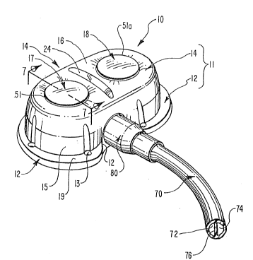
A perspective view of one embodiment of an implantable
access port 10 incorporating teachings of the present
invention is shown in Figure 1. Access port 10 generally
comprises a housing 11 which is itself comprised of three
plastic components that are bonded to each other. Only two
of these components, a base 12 and a cap 14, appear in
Figure 1.
During assembly, a septum support is bonded to the
base after which the septums are inserted into the septum
support and the cap is placed over the septum support and
the walls upstanding from the base. After assembly, the
bottom of the cap and the base may be bonded to form a
fluid-tight joint.
In an alternate method of bonding the components of
the access port involves bonding at the area surrounding
the septums. After the cap has been placed over the
septums, the areas near the top of the cap may be bonded to
the septum support which has previously been bonded to the
base.
Access port 10 also comprises a plurality of self-
sealing septums, such as self~sealing septums 17 and 18,
and an outlet stem not shown in Figure 1 by which a
catheter 70 is coupled to access port 10 and placed in
fluid communication with fluid cavities interior thereto.
-14-
Catheter 70 is a dual lumen catheter with the lumens 7
and 74 thereof, separated by a web 76.
A locking sleeve 80 enhances the lock of a catheter 70
over an outlet stem (not pictured).
In use, the distal end of catheter 70 is entered into
a major vessel of the cardiovascular system of a patient
and advanced therefrom, for example, into a position at the
superior vena cava. After catheter 70 is thusly
positioned, sufficient slack to allow for normal body
movement without straining catheter 70 is le~t in the point
of entry of catheter 70 into the vascular system. The free
end of catheter 70 is then tunneled from its point of entry
into the vascular system to a pocket in the tissue of a
patient. The catheter is then attached to the access port,
and the access port is secured into the pocket using
sutures installed through suture holes 13 formed in a
flange 19 about base 12. Generally, access port 10 is
placed in the chest wall (infraclavicular) on either the
right or the left side supported by the underlying ribs.
A pocket incision is made about the length and diameter of
base 12. Preferably, access port 10 is buried only about
0.50 inches tl.25 cm) below the skin, which is generally
sufficient to prevent access port 10 from eroding through
the skin. The pocket is then closed.
Septums 17 and 18 are configured such that they may be
punctured by a non-coring needle, and re-sealed after the
needle has been removed. Septums 17 and 18 are therefore
constructed from a self-sealing polymer such as silicone
rubber or latex.
According to one aspect of the present invention, the
housing 11 of an access port, such as access port 10~ is
provided with tactile means for determining the relative
locations of septums 17 and 18 through the skin of a
patient without simultaneously blocking access to either of
septums 17 or 18. By way of example and not limitation as
-15-
shown in Figures 1 and 2, a raised locating ridge 24
protrudes upwardly from cap 14. Locating ridge 24 is
positioned between and closely adjacent to septums 17
and 18. In the embodiment shown in Figure 1, raised
ridge 24 is substantially linear and is oriented so as to
be orthogonal to a line joining the centers of septums 17
and 1~. Such a configuration is, however, only exemplary,
as various other configurations of a locating ridge are
considered to fall within the scope of the present
invention~ Several will be disclosed subsequently relative
to Figures 14-19.
One important aspect of locating ridge 24 is that
locating ridge 24 does not encircle any enclosed area of
tissue. This ~limina~es the possibility of blood
restriction and the necrosis of tissue.
Once a physician has located raised ridge 24, the
physician immediately knows the location of both septums 17
and 18 on either side of locating ridge 24. It is not
necessary for the physician to locate one septum, and then
to have to search further for the additional of the
septums. Using locating ridge 24 the septums can be
located by tactile sensation without at the same time
impeding access to the septums for the purpose of effecting
an injection therethrough.
Access port 10 is constructed of a plastic material
which does not interfere with MRX or CAT scan ~iagnostic
imaging. Cap 14 is comprised of a top wall 16 having
formed therein a first septum access aperture 51 at a
position opposite a first fluid cavity (not shown) in
base 12 when base 12 is received in cap 14. A second
septum access aperture 51a is also formed in top wall 16,
but at a position opposite a second fluid cavity (not
shown) in base 12 when base 12 is received in cap 14. A
skirt 15 depends from top wall 16 of cap 14 to enclose
base 12 when base 12 is received in cap 14.
3?~
-16-
Septums 17 and 1g are captured in access
apertures 51, 51a sealing but affording access to the fluid
cavities located thereunder. Septums 17 and 18 are needle-
penetrable, while the remaining portions of access port 10
are needle-impenetrable. Cap 14 is ultrasonically welded
after assembly to base 12 either at top wall 16 a~out
septums 17 and 18 or at the bottom of skirt 15.
A more complete depiction of the components of access
port 10 is found in the exploded view thereof depicted in
Figure 2. There, access port 10 is shown to include not
only base 12 and cap 14, but a septum support 26 which is
disposed therebetween. Also in Figure 2, catheter 70 is
shown disconnected from an outlet stem 20 by which access
port 10 and catheter 70 are connected when implanted. The
interaction of lockiny sleeve 80, catheter 70, and outlet
stem 20 will be discussed in more detail later in the
description, in connection with Figures 9-12.
Base 12 has a flat floor 39 and generally curved
walls 41 normal to and upstanding therefrom. Walls 41
define a first fluid cavity 40 and a second fluid cavity 42
having non-circular cross sections when taken at a plane
parallel to floor 39. This is illustrated ~o better
advantage and discussed at length subsequently relative to
Figures 3 and 4.
A septum support shelf 43 serves as a stop for septum
support 26 when septum suppor~ 26 is assembled on base 12.
A dividing wall 44 separates fluid cavity 40 from fluid
cavity 42. Dividing wall 44 shares the same longitudinal
axis as slot 28 between prongs 54, 56 of outlet stem 20.
Dividing wall 44 in combination with upstanding walls 41,
forms a non-circular perimeter for cavities 40 and 42 in
base 12 of housing 12.
Recessed walls 45 extend upward beyond septum support
shelf 43 to receive the outer surface of septum support
wall 46 on the side of septum support 26 that nests against
-17~
base 12. Upon engagement of septum support 26 with septum
support shelf 43 and recessed walls 45, the lower inner
side 47 of wall 41 meets flush with the lower inner side of
septum support wall 46. Thereafter, septum support 26 is
bonded to base 12 preferably by ultrasonic welding.
Nevertheless, in lieu thereof alternate forms of bonding,
such as adhesive bonding, may be utilized.
Septums 17 and 18 are then inserted into septum
receiving apertures 49. In so doing, fluid cavities 40
and 42 become sealed. Fluid cavities 40 and 42 are then
bounded by floor 39, lower inner sidewall 47, lower inner
sidewall 48, and the bottom surface of septums 17 or 18~
It should be noted at this point that the cross~
sectional shape of fluid cavities 40 and 42 as illustrated
in Figure 3, for example, are definitively noncircular. It
is one function of septum support 26 to permit the use of
circular septums, such as septums 17 and 18, in conjunction
with a noncircular fluid cavity, such as fluid cavities 40
and 42. Advantageously, a circular septum such as
septums 17 and 18, can be easily subjected to radially
uniform support and compression, whereas a nonradially
symmetric septum, such as one designed to conform to the
cross section of a noncircular fluid cavity, will be
difficult to load in a radially uniform manner.
The radially uniform support and compression of a
septum contributes to the equal distribution of stresses
therein and to ~ong-term, nondestructive penetration by
non-coring needles.
Although much of the following discussion, for
simplicity, centers around one or the other of fluid
cavities 40 and 42, both cavities share the same
construction. A structure in one fluid cavity is mirrored
by a similar structure in the adjacent fluid cavity, as
base 12 is symmetrical when viewed along a line drawn
-18- 2 ~7`rj~2 ~
through the common longitudinal axis of dividing wall 44
and slot 28.
After septums 17 and 18 are inserted into septum
receiving apertures 49, cap 14 is placed over septum
support 26 and walls 41 of base 12 to enclose those
structures. The bottom surface of skirt 15 of cap 14 abuts
flange 19 on the exterior of walls 41. When cap 14 is
bonded to base 12, the upper surfaces 64 of septums 17
and 18 protrude through access apertures 51 and 51a in top
wall 16. Outlet stem 20 protrudes from a shoulder 78 on
base 12 which is received in a stem arch 53 formed in
skirt 15.
Septums 17 and 18 are received in septum receiving
apertures 49 through the engagement of the bottom surface
and sides of a septum perimeter ring 55 with the walls and
top surface of a perimeter ring shelf 61 on septum
support 26.
Likewise, septums 17 and 18 are retained in septum
support 26 by downward pressure exerted from the engagement
of the top of perimeter ring 55 by an outer perimeter 63 of
access aperture 51. This allows upper surfaces 64 of
septums 17 and 18 to extend beyond the top wall 16 of
cap 14 and, thereby, remain accessible to a physician.
Figure 3 is a plan view of base 12 illustrating in
further detail the configuration of fluid cavities 40
and 42. Lower inner sidewall 47 comprising a circular arc
ACB combines tangent.ially with both straight normal wall
portion 68a and S-shaped convex curved wall portion 69a to
form a non-circular perimeter to fluid cavity 42. Fluids
injected through one of septum 18 enter fluid cavity 42 and
travel through a transition region 65a which bounded by
minor arc AB shown in dashed lines, straight normal wall
portion 68a, and S-shaped convex curved wall portion 69a.
As illustrated by the arrows F in Figure 4, the flow
of the fluid out of fluid cavity 40 is directed to an exit
-19~
passageway 50 located in the narrowest portion of
transition region 65 and f~om there through ~he exit
passageway 67 to egress point 66 at the distal tip 57 of
prong 56 of outlet stem 20~
Figure 4 illustrates a broken-away portion of outlet
stem 70 showing the internal structures thereof, such as
exit passageways 50 and 52, stem exit passageway 67
and 67a, and egress points 66 and 66b at distal tips 57 of
each of prongs 54 and 56. Exit passageways 50 and 52
communicate respectively through stem exit passageways 67a
and 67 in stem 20 with fluid cavities 40 and 42,
respectively. Each stem exit passageway 67, 67a is
longitudinally formed through a separately configured
prong 54, 56, respectively.
Taken together, transition region 65 and 65a function
as outlet means for placing fluid cavity 40 and fluid
cavity 42 in fluid flow communication, respectively, with
exit passageway 50 and 52 and for directing from fluid
cavity 40 and fluid cavity 42, respectively, into each
respective exit passageway a flllid flow having a cross
section smoothly reduced in area from each fluid cavity to
the exit passageway corresponding thereto.
When a needle is inserted through either septum 17
or 18 into respective ~luid cavity 40 or 42, and fluid is
injected there into, fluid flows out of fluid cavity 40
or 42 through transition region 65 or 65a and into stem
channel 67 or 67a. The velocity of flow increases in
transition regions 65, 65a and is maximized at exit
passageways 50 or 52. The velocity or flow rate remains
constant through stem exit passageways 67 or 67a to egress
points 66 or 66a at distal tips 57 of prongs 54, 56.
Transition region 65 shares floor 39 of base 12 with
the fluid cavity 42. The sides of transition region 65,
however, do not share the generally circular configuration
of lower inner side wall 47 encircling fluid cavity 42.
2~ ?~
-20-
Instead, transition region 65 is bounded by a normal wall
portion 68 disposed normal to exit passageway 50 and a
convex curved wall 69 which directs the flow through fluid
cavity 42 in a direction toward exit passageway 52.
5Normal wall portion 68 and convex curved wall
portion 69 together therefore define a transition region 65
having a cross-section that gradually reduces in area from
fluid cavity 40 to exit passageway 50. ~t is an important
aspect of the present invention that the combination o~
10gently curved or straight walls at transition regions 65
or 65a minimizes sharp turns or edges, as well as dead
spaces, in the flow of fluid out of access port 10. Once
fluid has entered stem exit passageways 67 or 67a, the
parallel, straight sides thereof provide a smooth
15passageway in which the fluid may flow.
Outlet stem 20 is formed integrally with base 12,
thereby obviating any chances of leakage occurring between
outlet stem 20 and base 12. No intermediate stru~tures are
required to be placed between exit passageways 50 or 52 and
20egress points 66 or 66a to redirect the flow of fluid from
spatially separated fluid cavities 40 and 42 into the
lumens of an attachable catheter. The absence of such an
additional member is achieved by configuring fluid
chamber 42 so that exit passageway 52 is positioned at a
25distance from the axis of slot 28 equal only to one-half of
the thickness of web 76 of catheter 70. Correspondingly,
fluid chamber 40 is configured so that exit passageway 50
is positioned at a distance from the axis of slot 28 e~ual
only to one-half of the thickness of web 76 of catheter 70.
30According to one aspect of the present invention,
transition regions 65 and 65a comprise respectively first
and second interface means for placing fluid cavities 40
and 42 and fluid flow communication with exit
passageways 50 and 52, respectively and for directing from
35each respective fluid flow cavity into the exit passageway
-21-
communicating therewith a flow of fluid having a cross-
section that is smoothly reduced in area from the fluid
cavity to the exit passageway. Transition region 65
and 65a thus take the form generally of a funnel having a
large end thereof adjacent to and communicating ~ith fluid
cavity 40 or 42 and having the small end thereof ad]acent
to and communicating with exit passageway 50 or 52,
respectively.
As seen in overall perspective in the plan Vi2W of
Figure 3, each of fluid cavities 40 and 42 have a cross-
section in a plane parallel to floor 39 of base 12 which
comprises, in combination, a circle and a wedge-shaped
appendage in the form of transition region 65 or 65a,
having a vertex and first and second sides adjacent
thereof.
In each instance, the vertex of the wedge-shaped
appendage is located at exit passageway 50 or 52,
respectively, away from the circular portion of the cross-
section of each respective fluid cavity.
The first and second sides adjacent to the verte~ join
the circular portion of the cross-section at the
circumference thereof. The first side of the appendage is
linear, comprising normal wall portion 68, while the second
side of the appendage is S-shaped, comprising convex curved
wall portion 69.
Taken in another perspective, the cross-section of
fluid cavity 40, 42 taken in a plane parallel to floor 39
of base 12 comprises a generally round portion
substantially circled by lower inner side 47 of walls ~1,
a generally pointed portion remote from the round portion,
and a transition region smoothly connecting the round
portion to the pointed portion. In the embodiment
illustrated in Figure 3, fluid cavities 40, 42 assume a
droplet-shaped cross-section. The pointed portion of the
cross-section of fluid cavities 40, ~2 comprises the narrow
-22-
f~ .
terminus of transition regions 65, 65a at the outlet
passageways. These pointed portions are disposed on the
sides of fluid cavities 40 and 42 adjacent to each other,
so as to terminate at a distance from each other
substantially equal to the lateral separation of
lumens 72, 74 of catheter 70 or egress points 66, 66a of
outlet stem 20.
In other words, exit passageways 50 and 52 in the
present invention are spaced apart a distance equal
approximately to the width of slot 28 or web 76 between
lumens 72 and 74 of catheter 70. Having exit
passageways 50 and 52 so closely positioned eliminates the
need for any prior art intermediary member to transition
the passageways from spatially separated fluid cavities to
a proximity at which a catheter may be attached directly
thereto. In addition, the flow of fluid achieved out of
access port 10 is free from the circuitous paths, sharp
edges, or dead spaces produced by the use of such
intermediary members.
Figure 5 is a view of the bottom surface of septum
support 26. It is the bottom surface of septum support 26
which nests with the tops of walls 21 of base 12 to form
the fluid cavities 40 and 42. Lower inner sidewall 48 of
septum receiving aperture 49 forms the upper sidewall
surface of fluid cavity 42. When viewed from the bottom
surface as in Figure 5, the structures forming the top of
transition regions 65 and 65a may be clearly seen. Similar
to the corresponding walls 41 of base 12, the normal wall
portions 68 and convex curved wall portion 69 guide fluid
flowing from fluid cavity 42 into exit passageway 52.
As can be seen in Figure 5, transition region 65
provides a funnel-shaped approach to exit passageway 50
which is free from sharp turns and edges. The rate of flow
through transition region 65 increases as the cross-
sectional area of transition region 65 is reduced.
-23-
Transition region 65 is free of sharp edyes and turns,
which can cause turbulence and dead spaces, which can trap
stagnant fluid within the fluid cavity.
Figure 6 is partially broken away enlarged view of the
bottom surface of septum support 26 illustrating a
receiving groove 73 so shaped and sized so as to be capable
of receiving dividing wall 44 of base 12. It is important
to note that receiving groove 73 is very narrow, thus
affording the minimum separation possible between fluid
cavities 40 and 42 at the point at which transition
regions 65 and 65a taper to the smallest cross-sectional
area thereof at exit passageways 50 and 52, respectively.
This minimal separation allows the exit passageways formed
in the sides of the fluid cavities to be positioned in
side-by-side configuration without the need for an
intermediate structure to direct a pair of more distantly
positioned exit passageways into a similar side-by-side
configuration.
When assembled, receiving groove 73 on septum
support 26 is filled by dividing wall 44 on base 12 and
ultrasonically bonded therein.
The use of ultrasonic bonding processes to secure
base 12, cap 14 and septum support 26 imposes certain
structural constraints upon these components of housing 11.
In a general sense, the walls of each of these three
components of housing 11 must be of substantially similar
thickness. In this manner, during ultrasonic bonding, all
regions of the three components of housing 11 will absorb
a relatively similar quantity of ultrasonic energy per
volume, thereby reaching similar temperatures
simultaneously.
For this reason, none of base 12, cap 14, or septum
support 26 include any substantially bulky regions, and it
is toward this end, for example, that base 12 is provided
with a void 22 and septum support 26 is provided with a
--24--
void 23 in the regions thereof intermediate fluid
cavities 40 and 42 as shown in Figures 2 and 3.
Additionally, because ultrasonic bondiny results in
the generation on an almost immediate basis of molten
portions of the components to be bonded, and inasmuch as
those molten portions thereof tend to expand, the mating
faces of base 12, cap 14 and septums 17 and 18 are provided
with various voids into which such moltenized plastic can
expand.
Thus, for example, as seen to best advantage in
Figure 5 and thereafter in Figures 6-8, septum support
wall 37 on the lower surface of septum support 26 is
encircled by a recessed flash channel 79 into which such
molten plastic can expand. In this manner, molten plastic
does not force apart the components being bonded together
and such molten plastic ~lows into spaces such as flash
channel 79, in preference to critical areas, such as fluid
cavities 40 and 42.
Recesses 75 form the roofs of transition regions 65
and 65a when septum support 26 is affixed to base 12.
Convex curved wall portion 69 has an upper portion 77 which
is shaped identically to convex curved wall 69 of base 12.
By joining these two walls upon assembly, transition
regions 65 and 65a remain free of sharp ends and edges and
directs the flow of fluid smoothly into the exit
passageways.
Figure 7 is a cross-sectional view of an assembled
access port 10, such as that illustrated in Figure 1.
There, fluid cavity 42 is shown to be enclosed by floor 39
and lower inner side wall 47 of base 12, as well as lower
side wall 48 of septum support 26 and a bottom surface 71
of septum 18. Transition region 65 shown in Figure 7 to
the right of the circular portion of fluid cavity 42 is
shown presenting convex curved wall portion 69 to direct
the flow of fluid smoothly to the right as shown in
-25 ~ ~ ~ ~
Figure 7 into the region of reduced cross-sectional area of
transition region 65 at exit passageway 52 (not shown).
Also depicted in Figurs 7 is the interaction of
cap 14, septum support 26, and base 12 to form the
housing 11 surrounding fluid chamber 40. When engaged,
septum support 26 is in contact with septum support
shelf 43. Septum 17 is supported on perimeter ring
shelf 61 of septum support 26 and is permanently held down
on perimeter ring shelf 61 by outer perimeter 63 of access
aperture 51 in cap 14. Septum 17 is preferably held in
place by the bonding of cap 14 to the top of septum
support 26 or by the body of the bottom surface of skirt 15
to flange 19 of base 12.
Figure 8 is a cross-sectional view taken along section
line 8-8 in Figure 7 to further illustrate transitional
areas 65 and 65a. Septum 17 and 18 are retained between
perimeter ring shelf 61 of septum support 26 and outer
perimeter 63 of access aperture 51 located in cap 14.
Fluid cavity 42 is shown formed between bottom surface 71
of septum 18, lower inner side wall 47 of wall 41, lower
inner side wall 48 of septum support 26, and floor 39 of
base 12. Normal wall portions 68 are shown adjacent each
of exit passageways 50 and 52 in the transition regions 65
and 65a approaching those exit passageways. As can be seen
in Figure 8, sharp turns or edges are minimized to fluid
flowing from fluid cavity 42 into exit passageway 52.
In use, a needle pierces septum 18 and fluid may then
be injected into fluid cavity 42 for advancement through
transition region 65a to exit passageway 52. In transition
region 65, however, turbulence and vortex action is kept to
a minimum and stagnation areas are avoided.
Figure 9 illustrates an end view of outlet stem 20
having formed in each of prongs 54 and 56 thereof stem
channels 67 and 67a. Slot 28 defined between prongs 54
and 56 is capable of receiving web 76 of multi-lumen
-26- 2~ ~ ~6~'?~
catheter 70. Although the outlet stem illustrated in
Figure 9 is configured for use in a dual-lumen catheter
having lumens which are generally D-shaped, catheters
having a plurality of lumens having other configurations
and correspondingly shaped prongs on an outlet stem also
fall within the scope of the present invention. In each
instance, the number and shape of stem channels 67 and the
outer surfaces forming the prongs thereabout are configured
so as to correspond with the number and shape of the lumens
of the catheter to be slid over the prongs.
Figure 10 is a plan view of outlet stem 20 of Figure 9
showing in disassembled state therewith catheter 70 and
locking sleeve 80. These are also illustrated in Figure 2.
To assemble these elements, the proximal end 88 of
catheter 70 is slid over the distal tip 57 of prongs 54
and 56. As the outer diameter of prongs 54 and 56 at
distal tip 57 is smaller than the internal diameter of
catheter 70 at this point, a small amount of pressure is
needed to engage catheter 70 over distal tip 57.
Continued pressure in the direction toward housing ll,
will, however, force catheter 70 onto barb ramps 31 and 31a
on barbs 60 and 62, respectively. The tip 90 of barbs 60
and 62 represents the region wherein barbs 60 and 62 have
the greatest circumference. The circumference of barbs 60
and 62 at tip 90 is greater than the inside diameter of
catheter 70. As a result, a great degree of resistance to
the advancement of catheter 70 arises at tips 90.
Further pressure on catheter 70 in the direction of
housing 11 causes pro~imal end 88 of catheter 70 to pass
over tips 90 and onto a reduced region 32 having an outer
circumference that is less than the inner~circumference of
catheter 70. Little resistance to the advancement of
catheter 70 is encountered in this area~
As catheter 70 is advanced farther onto outlet
stem 20, proximal end ~8 of catheter 70 encounters a ramped
-27- ~ ~ 7~
surface 33, having a ramp of gradually increasing
circumference termi.nating in a renitent surface 34.
~enitent surface 34 has a circumference greater than the
internal circumference o:E catheter 70.
Catheter 70 i5 inserted over outlet stem 20 to a point
where the inner web 76 of the dual lumen catheter
encounters the end of slot 28. Locking sleeve 80 is then
slid along catheter 70 and pressed onto outlet stem 20.
Figure 11 is a cross-sectional view taken along
section line 11-11 in Figure 10 further depicting the inner
structure of the locking sleeve 80. Although many
configurations of locking sleeves fall within ths scope of
the present invention, a locking sleeve 80 is utilized in
a presently preferred embodiment of the instant invention
having on the exterior thereof a pressure application
ridge 102 which provides a ridge upon which a physician may
press when forcing locking sleeve 80 over catheter 70 and
outlet stem 20.
To install locking sleeve 80 over catheter 70, a
proximal en~ 104 thereof is slid over the portions of
catheter 70 covering barbs 60 and 62 until proximal end 104
encounters the portion of the catheter covering ramped
surface 33. As the diameter of the opening of locking
sleeve 80 at proximal end 104 is greater than the diameter
of tip 90 and reduced area 32, no pressure is exerted by
proximal end 104 until proximal end 104 encounters the
portion of the catheter covering the ramped surface 33.
Before proximal end 104 reaches ramped surface 33 and
renitent surface 34, however, an internal ramp 106 of
locking sleeve 80 begins to encounter other structures of
outlet stem 20 covered by catheter 70. The diameter A of
the inside of locking sleeve 80 at the narrowest point 100
of internal ramp 106 is slightly less than the diameter of
tip 90 of barbs 60 and 62 when catheter 70 is slid
thereover. As a result, as internal ramp 106 encounters
-28- ~ ? ~
the catheter covering tip 90 of barbs 60 and 62, increased
resistance is encountered to the advancement of locking
sleeve 80.
As internal ramp 106 is pressed over tips 90 of
barbs 60 and 62, however, the narrowest point 108 of
internal ramp 106 passes to the side of tips 90 adjacent to
housing 11. From narrowest point 108 of internal ramp 106
to distal end 110 of locking sleeve 80, the internal
diameter B thereof becomes progressively larger than
diameter A. This difference between diameters A and B thus
concentrates the compression of the catheter at or proximal
of the barbs. As a result, energy must be introduced to
remove the locking sleeve from the portion of the catheter
located above the barbs. Thus, once narrowest point 108
has passed over tips 90 of barbs 60 and 62, the internal
configuration of locking sleeve 80 tends to bias locking
sleeve 80 to remain in position on stem 20.
The radial pressure exerted inwardly by the locking
sleeve compresses barbs 54 and 56 into slot 2~. This then
compresses web 76 of catheter 70. The region above the
harbs produces the most renitent force. This area of
greatest compression also sealingly compresses the barbs
against the web of the catheter.
The access port is provided with means for biasing the
locking sleeve into a locking position on the outside of
the catheter when the proximal end of the catheter is
received on the outlet stem. By way of example and not
limitation, the means for biasing provided in the
embodiment illustrated in Figure 11 comprises locking
sleeve 80, internal ramp 106, and a gradually tapering
surface, delineated by the surface between diameter arrow
A and diameter arrow B in Figure 11. The gradually
tapering sur~ace requires the input of energy to remove the
locking sleeve from the catheter.
-29- 2~
Figure 12 illustrates locking sleeve 80 in its
assembled position over catheter 70 on outlet stem 20.
Proximal end 104 of locking sleeve 80 is shown abutted
against a face 38 of shoulder 78. As the proximal end 88
of catheter 70 does not extend to this point, no pressure
is exerted on outlet stem 20 there.
An area of substantially uniform pressure exists in
the region where catheter 70 is in contact with renitent
surface 34. Pressure exerted on prongs 54 and 56 increases
in the region where internal ramp 106 is positioned in
contact with ramped surface 33. As this radial pressure
from the outer walls of catheter 70 forces prongs 54 and 56
together, pressure is exerted therebetween on web 76
located in slot 28 thereby sealing the interface
therebetween.
The area of greatest pressure occurs in the region
surrounding tip 90 of barb 60 and 62. Although the
internal diameter of the locking sleeve is increasing at
this point, the presence of barbs 60 and 62 greatly reduces
the distance between the outer surface of prongs 54 and 56
and the inner surface of locking sleeve 80. This insures
that catheter 70 and locking sleeve 80 will be retained on
outlet stem 20.
By way of example and not limitation, a triple-cavity
access port 85 capable of being utilized with a triple
lumen catheter is illustrated in Figure 13. Septums 81 are
shown captured within the housing 82 thereof enclosing
three fluid cavities (not pictured). An outlet stem 87
comprised of three prongs 83 provides support for a triple
lumen catheter (not shown) having generally wedge or
triangular shaped lumens. These communicate through egress
points 84 of an exit passageway in each o~ outlet stems 83.
Pressure exerted by the exterior wall of the catheter
against the sides of prongs 83 urges these into a Y-shaped
-30-
slot 86 which is filled with a Y-shaped web when a catheter
is slid over this outlet stem.
Figures 14-19 illustrate various embodiments of
locating ridges contrasted with the locating ridge 24
illustrated in Figures 1 and 2. Each locating
ridge outlines to some degree the configuration of one or
both of septums 17 and 18 positioned adjacent thereto.
As an example, Figure 14 depicts a third embodiment of
an access port provided with a locating ridge 24a having an
S-shape. Figures 15 and 16 depict locating ridges 24b
and 24c, respectively, having enlarged ends. Figure 17
depicts a linear locating ridge 24d disposed parallel to
and in line with a line joining the centers of septums 17
and 18. It is important to note, however, that septums 17
and 18 are not completely enclosed by locating ridge 24,
since this could result in necrosis of the tissues thusly
encircled.
In Figure 18, locating ridge 24e further comprises a
first indicator means for identifying the relati~e
direction from locating ridge 24e of one of septums 17
or 18. As shown by way of example in Figure 18,
appendage 25 extends from the outer curve of locating
ridge 24e toward septum 18.
As shown in Figure 19, a second indicator means is
provided for identifying the location of stem 20 relative
to septums 17 and 18. There otherwise linear locating
ridge 24f is provided at the end thereof adjacent to
stem 20 with an enlarged head 25a taking the form of an
arrow.
Utilizing appendage 25 or appendage 25a, a physician
palpating the location of the access port through the skin
of a patient can be provided with information about the
relative location of various structure elements of the
access port.
-31-
The invention may be embodied in okher specific forms
without departing from its spirit or essential
characteristics. The described embodiments are to be
considered in all respects only as illustrative and not
restrictive. The scope of the invention is, there~ore,
indicated by the appended claims rather than by the
foregoing description. All changes which come within the
meaning and range of equivalency of the claims are to be
embraced within their scope.