Note: Descriptions are shown in the official language in which they were submitted.
WO92/1~388 P~T/US9t/0976~
-1- 2 ~ r~
PASSIVE BUILDING VENTS
BACKGROUND OF T~E INVENTION
1. Field of the Invention
The present invention relates to vents, and more par-
ticularly to a pa~sive building vent which is suitable for
installation in the outside wall of a multi-story building
thereby equalizing the air pressure within the building to
the outside atmospheric pressure.
10 2. Discussion of the Relevant Art
Numerous types of buildinq vents are in use today.
Their specific purpose is to provide a device for
--exhausting air from a confined space to the outside when~
the confined air either reaches a prescribed temperature
15 or odoriferous p~rticles have been trapped within the con-
fined space and it is desiraDle to release the confined
air to the outside atmosphere. In some instances these
;~ vents are utilized in conjunction with attic vents, which
may be passive or powered, and they assist in the
20 discharge of the confined air to the outside atmosphere.
T~pical of these vents is an ener~y saver damper
assembly disclosed in U.S. Pa~ents 4,591,092, 4,596,181 r
and 4,567,816 invented by the inventor of the subject
invention. In addition to providing the normal venting
25 function, the uni~irectional vent provides for the
~ equalizing of air pressures should a sudden drop in the
- outside or atmospheric air occur, such as experienced
during tornados or other violent air disturbances. The ~;
u~ique property of the unidirectional vent is that it per-
30 mits a prescribed amount of air to escape from a confined
air space yet it provides for an instantaneous increase in
the amount of air permi~ted to escape with sudden drops in
outside or atmospheric air pressure. The feature prevents
the confined air f~om causing damage to windows, and the
s_ like, with sudden drops of atmospheric air pressure.
.~ . .
~;UeSTlTl~Tl~ ~;HE~T ~
. .` `` ` .. .` ~ ::.. ., .. - .,. , .,. .- . - ,
WO92/1~3X8 PCT/U~91/097
2-
The instant invention is ideally suited for use in
multi-~tory buildings wherein the confined inner space may
be continuously equali2ed with the outside atmospheric air
5 and when combined with the unidirectional air vent can
compensate for sudden drops in the outside atmospheric
pressure. Thus the normal "chimney-like" effect which is
caused in multi-story or high rise buildings when they are
provided with a central heating or air conditioning system
10 may now be eliminated, since the air pressure at each
story is equalized to the outside air pressure. This
decreases if not eliminates the drawing in of additional
- outside air into the system which would require-additional
capacity for the heating and air conditioning systems uti-
15 lized therein.
Water seeks its own level. In a similar way, if
moisture is not provided an engineered path, it will find
its own way out of a building. Most often this will be in
the least desirable fashion through the structure
20 itself, causing, at worst, severe structural degradation.
Common symptoms are failed pointing on walls (which
results in months of effort and huge dollar outlays), and
the impairment of the roof through - successively -
blistering, cracking, leaking, and ultimately disin-
25 tegration. If ambient (airborne, environmentnal) moistureremains trapped, micro-organisms (mold, fungus) will grow.
This has an adverse effect on the health and productivity
of tenants and employeesO
If buildings are vented in accordance with the pre-
30 sent invention, moisture exits through designed pathways.The structural integrity of the building is maintained.
Building facia remains intact and walls do not accumulate
mold. The roof underlayment remains dry and roof life is
extended. In addition, ambient moisture leaves through
3~ the vents, the conditions which enable mold to thrive are
~uE3s~lr~ S~tEE~
.
~, : .
. . . .
WO92/123~ PCT/~S91/09764
2 0 7 ~
eliminated, and both health and productivity of occupants
are maintained. A well-vented, dry building will not
manifest the "sick building" syndrome.
The passive venting system of the present invention
uses no fans, motors, or electricity, and is continuously
working. The passive vent is also easily retrofitted into
most shapes and styles of window. It also has the advan-
tage of moving air in one direction only, exhausts in-
ternal air continuously, allows no infiltration, conserves
energy, windows remain closed and is tamper~resistant.
The passive vent also addresses all indoor air
quality problems--i-n-apartments and office buildings, which
are mold and mildew, condensation and dripping windows,
odors and obnoxious smells, and sick building syndrome.
OBJECTS OF THE INVENTION
Therefore, it is an object of the present invention
to provide a passive building vent which is reliable and
easily installable in multi-story buildings.
It is another object of the present invention to
provide a reliable building vent capable of equalizing the
air pressures between the confined air space and the
atmospheric air with sudden drops in atmospheric air
pressure.
It is another object of the present invention to
provide a passive building vent suitable for use in high
rise buildings which insures that the confined building
air may be vented to the outside even when circulating
atmospheric air currents flow in an upwardly direction.
It is yet another object of the present invention to ;~
provide a method for venting a multi-story building when
low velocity outside atmospheric winds impinge directly
upon the passive building vent.
It is still another object of the present invention
to provide a passive building vent that provides for
SUBSTITUTE SHEET
.. - : :. ~ : ........................... .:
,, : : ~: ~:: :.,
WO92/1~388 PCT/US91/097~
6~r~
venting the confined air into the outside atmospheric air
automatically as normal winds impinge directly upon the
passsive building vent.
The present apparatus overcomes the shortcomings of
the known art by providing a reliable, relatively inexpen-
sive, venting apparatus which is passive and contains only
one moving part.
SUMMARY OF THE INVENTION
A passive building vent disposed in an outside ver-
tical building wall, in operative relationship to an
opening provided in the outside building wall for com-
municating between the outslde atmospheric air and the
confined air within the building that includes a hou~ing
15 means adapted to be disposed in the-building opening bet-
ween the confined air and the outside air forming an air
; mixing chamber and having a passageway disposed there-
`` through. Movable membrane means are mounted within the
housing means at one end of the passageway, the other end
2n of the passageway communicating with the confined air and
disposed outside of the vertical building wall, with the
membrane means having a closed position, substantially
blocking the passageway and an open position, permitting
the free flow of air there-through, and the membrane means
25 being in its closed position when at rest.
` Air passage means is disposed on the housing maans
for permitting the flow of outside air into the air mixing
` chamber, with venting means disposed in the upper sur~ace
of the housing means communicating with the air mixing
30 chamber for permitting the fiow of air to exit from the
air mixing chamber, and deflector means mounted on the
housing means proximate the venting means and com-
; municating with the air mixing chamber. The deflector
means being inclined relative to the membrane means and
interposed between the membrane neans and the venting
SuE~srlTuTE SHFET
,. .- .................... .. .
, ~ : , ,. , ~ ,
, , :. , ~. : :
WO92/12388 2 0 ~
means, wherein the ~low of outside air entering through
the air passage means impinges upon the deflector means
and is forced to exit through the venting means providing
5 a pressure differential such that the membrane means is
caused to move to its open position permitting the free
flow of the air through tbe passageway into the air mixing
chamber for venting the building.
The air passage means is provided with vanes for
10 diverting the outside air towards the venting means and
may include a plurali~y of horizontally extending louvres
with upwardly extending openingsO The air passage means
ls disposed at an upwardly and outwardly extending angle
relative to the membrane means in its closed posltion,
15 wherein wind or warm thermals that radiate off of the
building rise and can pass through the vanes into the air
mixing chamber.
The foregoing and other objects and advantages will
appear in the description to follow. In the description
~0 reference is made to the accompanying drawing which forms
a part hereof, and which is shown by way of illustratio
specific embodiments in which the invention may be prac-
, ~iced. The embodiments will be described in sufficient
detail to enable one skilled in the art to practice the
25 invention and it is to be understood ~hat othex embodiments may be utilized and that structural changes may be
made without departing from the scope of ~he invention.
In addition the passive building vent may be mounted in an
inverted or vertical position relative to that shown in
30 the drawings and also be used. The following detailed
description is, tberefore, not to be taken in a limited
sense wherein like reference numerals refer to like parts
throughout the several views, and the scope of the present
invention it is best to find by the appended claims.
BRIEF DESCRIPTION OF THE DRAWING
SUBSTITUl E SHEET
, ;,
. , ., ; ,
W~g2/1238~ PCT/US91/0976
In order that the invention may be more fully
unders~ood, it will now be described, by way of example,
with reference to the accompanying drawing in which:
FIG. l is a perspective pictorial representation of
a multi-story building in which the apparatus of the ^~
instant invention is installed;
FIG. lA is an enlarged fragmentary view of the
apparatus of the present invention installed in an outside
10 wall of the building;
FIG. 2 is an enlarged perspective view of the
apparatus shown in FIG. l installed in an outside wall of
the building; - --
FIG. 3 is a side view of the apparatus of the pre- :
15 sent invention installed in an outside wall of the
building;
FIG. 4 is an enlarged cross-sectional view of the
passive air vent, according to the principles of the pra-
sent invention;
FIG. 5 is a pictorial representation of the appara-
tus in elevation, showing the position of the venting
membrane with relatively low velocity air passing
therethrough;
FIG. 6 is a pictorial representation of the appara-
25 tus in elevation with relatively high velocity air passing
therethrough;
FIG. 7 is a front view, partially broken away, of
the apparatus of the present invention;
. FIG. 8 is a perspective view of another embodi~ent
30 of the present invention, partially in section installed
in an outside wall of the building;
FIG. 9A is a pictorial representation of the appar-
tatus in elevation, showing the position of the venting
membrane ~ith relatively low velocity air passing
35 therethrough; and ~:
~;UBSTITUTE SHEET
,. .. . .................. . .
..
..
, " , .. ..
, . . ..
-, ' ~ ,, . ' ' ` ';' ~ ` , .. .. .
W092/12388 PCT/US9l/~9764
2 ~ 3,~
FIG. 9B is a pictorial repr0sentation of the appar-
tus in elevation with relatively high velocity air passing
therethrough.
DESCRIPTION OF THE PREFERRED EMBODIMENTS
Referring now to the figures, and in particular to
FIGS. 1 through 4, which show the passive building vent 10
installed in a plurality of positions proximate the
ceilings of each of a plurality of floors in a multi-story ~:
10 building 12. Typically these multi-story buildings are
used for apartment houses, industrial or commercial use.
The windows 14 provided therein may be of the type ~:
generally not made to open or of a conventional-style in - :
apartment houses that can be opened. Thus, each of the
15 floors in a multi-story commercial type building is at-a
different atmospheric pressure, since there is no opening
or venting to the outside atmosphere 16. As is well known
by those Knowledgeable in the art, when providing:heating
and cooling, normally positioned in the basement of the
20 building, to the various floors, a chimney effect occurs,
thus causing additional atmospheric air to enter the .
building a- the forced air is pushed to the upper stories
during heating and air conditioning. The addition of out- ;
side or atmospheric air into the building increa3es the
25 load on the heating and cooling systems. A plurality of
the passive building vents 10 being installed in or on the
outside vertical wall 18 which communicates between the
confined air space in the building causes the equalization
of the confined air 20 with the outside atmospheric air
30 16.
Referring now to FIGS. 2 through 7 which show the .
passive building vent 10 installed in an outside bullding
wall 18 which may be installed from the outside or
exterior surface 22 of the wall 18 and communicates with
35 the inside or interior surface 24. An opening 25 is pro-
SlJBSTlTUTE SHEET
WO 9~/~23g~ Pcr/ussl/os764
~ 3
vided between the interior surface 24 and exterior surface22. The opening 25 may be formed by a conduit 2Ç formed
of a plastic or metallic material formed to coincide with
the shape of the vent 10, to permit a flow of confined air
20 in the direction of arrows 28 in the manner hereinafter
described in detail.
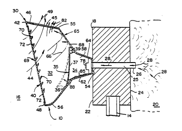
As further illustrated in FIGS. 2, 3 and 4, the
passive building vent 10 may be disposed on the outside
0 building wall 22, in operative relationship to the opening
25 provided in the outside building wall 22 for com-
municating between the outside atmospheric air 16 and the
confined air 20 within the building 12. The vent 10-
includes housing means 30 adapted to be disposed in com-
5 municating relationship with the building opening 25 bet-
ween the confined air 20 and the outside air 16 forming an
air mixing chamber 32 and having a passageway 34 disposed
therethrough and communicating with opening 25. Movable
membrane means 35 is mounted within the housing means 30
20 at one end of the passageway 34, the other end of the
passageway 34 communicating with the confined air 20 and
disposed out~ide of the vertical bui:Lding wall 22, with
the membrane means 35 having a closed position as
illustrated in FIG. 5, substantially blocking the passa-
~5 geway 34 and an open position as illllstrated in FIG. 6,permitting the free flow of confined air 20 therethrough
in the direction of arrows 28. The membrane means 35 is
in its closed position when at rest by gravitational for-
ces as illustrated in FIGS, 4 and 5 and has a lower free
30 edge or end 36 and an upper fixed ~dge or end 38 at each
end of the flexible member 37. The flexible member 37 may
be fabricated from Mylar and is between ~ mils and
approximately 2 mils thick. An ideal thickness has been
f~und to be ~ mils thick~ The upper edge 38 may be con-
35 nected to support means 39 coupled to the housing mea~s
SUBS~ITUTE SHEET
~ . . . .. .
.. : . ,, . . ., . , ~ ,
WO~2/123~8 PCT/US91/097~
9 2 ~
30. The upper edge 38 may be adhesively secured to thesupport means 39 as one form of attachment. Other forms
of securment may also be used as well as various other
5 flexible materials.
Air passage means 40 is disposed at the outside
distal end 42 of the housing means 30 for permitting the
flow of outside air 16 as illustrated in the direction of
arrows 44 into the air mixing chamber 32, with venting
10 means 45 disposed in the upper surface 46 of the housing
means communicating with the air mixing chamber 32 for
permit~ing the flow of air to exit from the air mixing
chamber 32. The venting means 45 may include a plurality
of spaced apart slots or grooves 47 that may vary in con-
15 figuration and size to permit air to exit therethrough asillustrated by the arrows 49.
The housing means 30 may have an elongated con-
figuration as seen in FIGS. 2 and 7 and fabricated from a
plastic material to include a front wall 48 connected to a
20 pair of side wall portions 50 and 52 affixed to the front
wall 48. One configuration of the housing means 30 may be
in which the side walls 50 and 52 are about 7" apart and
~he height of the housing means 30 is about 2.75".
obviously the dimensions may vary accordingly. A rear
25 wall 54 is affixed to the side walls 50 and 52, and an
upper wall 55 forms the upper ~urface 46 of the housing
means 30. A bottom wall 56 connects the rear wall 54 to
the front wall 48. ~he passage means 40 is in com-
municating relationship to the front wall 48 and the
30 venting means 45 is in communicating relationship to the
upper surface 46.
The upper surface 46 may be inclined upwardly rela-
tive the vertical wall 54 at an angle of approximately 5
degrees to 15 degrees or be fabricated in a horizontal
plane. An angle OL approximately 9 degrees has been found
S~JBs~lT~l~E SHE~T
:: :. : :. : . ~ . ,:: :: ::::...... ,.. , .,, ,. ,;...... : ::
' ~ , " .' '
. . . ~ ,
WO92/12388 PCT/US9l/097~
--10--
to operate well. The side walls 50 and 52 may have a con-
toured configuration with rear sections or portions 58 or
60, respectively. The sections 58 and 60 may be tapered
5 to terminate at the rear wall 54. In addition, to guide
the flow of air 20 in the direction of arrows 28, the bot-
tom wall 56 may have a tapered rear end or section 62 and
the upper wall 55 may have a tapered rear end or section
64.
Deflector means 65 is mounted on the housing means
30 proximate ~he venting means 45 and communicating with
the air mixing chamber 32. The deflector means 65 being
inclined relative to the membrane means 35 and interposed
between the membrane means 35 and the venting means 45,
5 wberein the flow of outside air 16 entering through the
air passage means 40 impinges upon the deflector means 65
as illustrated by arrows 66 in FIG. 4, and is forced to
exit through the venting means 45 providing a pressure
differential such that the membra~e means 35 is caused to
20 move to its open position as illustrated in FIG. 6, per-
mitting the free flow OL the air 20 through the passageway
34 into the air mixing chamber 32 for venting the building
12. The deflector means 65 includes a deflector member 68
that is inclined at an angle relative to the vertical
25 plane defined by the rear wall 54 or the movable membrane ~;
means 35 when in its vertical position as illustrated in
FIGS 4 and 5. The inclined angle of deflector member 68
may be in the range of 30 degrees to 60 degrees and pre-
ferably at approximately 45 degrees.
The air passage means 40 is provided with vanes 69
for diverting the outside air 16 towards the deflector
means 45 and may include a plurality of horizontally
extending louvres 70 with upwardly extending or inclined
shoulders 72. The air passage means 40 is disposed at an
35 upwardly and outwardly extending angle which may be in the
Sl~BSTlTU~E ~EET
,.:
; . '~' :
, . , . ., ~ ~ . .. .
W~92/1238~ PCT/US91/097~
2 ~ 3 `~
range of 15 degrees to 45 degrees relative to the membrane
`: means 35 in its closed position, wherein wind or warm
thermals that radiate off of the building 12 rise and can
5 pass through the vanes 69 into the air mixing chamber 32.
An angle approximately 20 degrees has been found suitable.
The passive ~uilding vent 10 further includes
mounting means 75 for removably coupling the housing means
30 to the building 12. As illustrated in FIG. 7, the
10 mounting means 75 is adapted at one end thereof for
affixing the building vent lO to the outside vertical wall
22 of the building 12. The mounting means 75 may include
; spaced apart holes 76 that are adapted to receive a bolt
. _ .. . . ................. . . . .
~ or fastener 78 therethrough which as illustrated in FIG. 4
: -l5 may extend through the wall 18. It is understood that
holes will be provided in the wall 18 which may be the
frame of the window 14 or even the glass itself. An adhe-
sive bonding could also be used to secure the building
ven~ 10 in fixed relationship to the building 12.
The operation of the passive building vent is best
illustrated together ~ith FIGS. 4, 5, and 6. FIG. 2 and
disclo~e the position of the movable membrane means 35
under steady sta~te conditions with the vent lO installed
in the building 12 and without atmospheric air flow
2~ impinging upong the deflector means 65. The unidirec-
tional vent lO is initially in its clo~ed positioned, as
shown in FIGS. 4 and 5. In its open position or fully
open condition, as shown in the broken lines in FIG. 2 or
the open position in FIG. 6 the mylar membrane means 35 is
30 free to move with air currents as shown .
The atmospheric air impinges on the passive building
vent lO through the air passage means 40 in the direction
of arrows 44 and 66 (FIG. 4), with a certain amount of air
impinging upon the deflector means 65 to essentially cause
35 the free end 36 of the flexible member 37 to move to the
SUBSTITUTE SHEET
.
WO92/12388 PCT/US91/09764
.,~9
9 ~ ~ 3
-12~
open position illustrated in FIG. 6. Air exiting from the
confined air space 20 will take the path shown by the
arrows 28, through elongated apertures 80 (See FIG. 7),
5 around the free end 36 of the flexible member 37 and will
then move into the air mixing chamber 32 and essentially
move in a manner as illustrated by arrows 81 and then move
upwardly as illustrated by arrows 82 that exit through the
openings or slots 47 illustrated in FIG. 3. Obviously the
10 configuration of the slots 47 and apertures 80 m2y vary in
size, shape and configuration.
The air paths will be as that shown in FIG. 6 and
will flow in the direction of arrows 28, 81 and 82 and the
.. . ... .
confined air 20 will be removed from the building 12. The
15 ~xiting confined air 20 in the building 12 will combine
with the atmospheric air 16 and exit from the venting
means 45 in a unique method. Thus, regardless of the
velocity of the atmospheric air speed or its direction,
venting can be accomplished from the confined air space 20
20 to the outside atmosphere 16. If a sudden drop of
atmospheric pressur- should occur, the membrane 37 moves
toward its vertical or rest position as illustrated in
~FIGS. 4 or 5 thereby preventing the confined air 20 to
exit the building and thus, equalize the pressure instan-
25 taneously. Accordingly the angle of inclination of thelouvres 70 forces the inwardly directed air indicated by
arrows 44 to be projected against the surface of the
deflector means 65 which is inclined relative to the
membrane means 35 and thereafter exiting through the
30 venting means 4;. The surface formed by the venting means
45 may he inclined as illustrated or perpendicular to the
vertical plane of the building 12. Concurrently as the
external air 16 flows as above described, an initial dif-
ferential o~ pressure is created causing the free end 36
3~ of the flexible member to move outwardly creating a path
SUBSTITUTE SHEET
.:
. .
. WO92/12388 PCT/US91/097~
2~7~5~
-13-
for the exiting of the confined air 20 such that the air
can flow and exit from the building through the mixing
: chamber 32 and thereafter exit through the venting means
5 45 in the same direction as the outside air 16.
To prevent the membrane means 35 from being
deflected under pressure towards the passageway 34, such
as by a strong rain or water from a hose which could per-
~; mit the entry of water or other liquid into the passageway
10 34 and in turn the building 18, there is provided
resisting or ~top means 85. One such embodiment being ~-
illustrated in FIGS. 4 and 5 illustrates that the
resisting means includes a plurality of steps 86 contained
on the rear end 62 with a front step or stop 88 in
15 abutting relationship to the flexible member 37. In this
manner a dual function is performed in that the stop 88
prevents the rearward flexing of the membrane 37 and
further the s~ops 86 also prevent water from flowing
upstream in case any would seep through.
Referring now to FIGS. R, 9A and 9B, which show the
passive buildinq vent 10a installed in a position similar
to that illustrated in FIGS. 1-7 of a multi-story building
12a. The windows 14a provided therein may be of the type
generally not made to open or of a conventional style in
25 apartment houses that can be opened. Thus, each of the
floors in a multi-story commercial type building is at a
different atmospheric pressure, since ther~ is no opening
or venting to the outside atmosphere 16a. As is well
known by those kno~ledgeable in the art, when providing
30 heating and cooling, normally positioned in the basement
:~ of the building, to the various floors, a chimney effect
occurs, thus causing additional atmospheric air to enter
the building as the forced air is pushed to the upper
stories during heating and air conditioning. The addition
of out~ide or atmospheric air into the building increases
SUBSTITUTE SHEET
WO92/123~8 PCT/US91/~97
~ -14-
the load on the heating and cooling systems. A plurality
of the passive building vents lOa being installed in or on
the outside vertical wall 18a which communicates between
5 the confined air space in the building causes the equali-
zation of the confined air 20a with the outside atmos-
atmospheric air 16a.
The passive building vent lOa is installed in an out-
side building wall 18a which may be installed from the out-
10 side or exterior surface 22a of the wall 18a andcommunicates with the inside or interior surface 24a. An
opening 25a is provided between the interior surface 24a and
exterior 3urface 22a. The opening 25a may be formed by a
conduit 26a formed of a plastic or metallic material formed
15 to coincide with the shape of the ven~ lOa, to permit a flow
of confined air 20a in the direction of arrows 28a in the
manner hereinafter described in detail.
The passive building vent lOa may be disposed on the
outside building wall 22a, in operative relationship to the
20 opening 25a provided in the outside building wall 22a for
communicating between the outside atmospheric air 16a and
the confined air 20a within the building 12a. The vent lOa
includes housing means 30a adapted to be disposed in com~
municating relationship with the building opening 25a bet-
25 ween the confined air 20a and the outside air 16a forming anair mixing chamber 32a and having a passageway 34a disposed
therethrough and communicating with opening 25a. Movable
membrane m0ans 35a is mounted within the housing means 30a
at one end of the passageway 34a, the other end of the
30 passageway 34a communicating with the confined air 20a and
disposed outside of the vertical building wall 22a, with the
membrane means 35a having a closed position as illustrated
in FIG. 9A, substantially blocking the passageway 34a and an
open position as illustrated in FIG. 9B, permitting the free
flow of confined air 20a therethrough in the direction of
SUBSTITUTE SHEFT
. "
, ,, ; ~ , : ~ . ., "
, ,, ., , ,-, . . ,.,. : ; ..
WO92/12388 ~ PCT/U~91/09/64
297~9~9
-l5-
arrows 28a. The membrane means 35a is in its closed posi-
tion ~hen at rest by gravitational forces as illustrated
in FIGS. 8 and 9A and has a lower free edge or end 36a and
5 an upper fixed edge or end 38a at each end of the flexible
member 37a. The flexible member 37a may be fabricated
from Mylar and is between ~ mils and approximately 2 mils
thick. An ideal thickness has been found to be ~ mils
thick. The upper edge 38a may be connected to the housing
10 means 30a in a variety of ways. The upper edge 38a may be
adhesively secured to the deflector means 65a as one form
of attachment. Other forms of securment may also be used
as well as various other flexible materials. The free
edge 36a may be spaced from the housing partition or neck
88a to provide an air gap therebetween.
Air passage means 40a is disposed at one outside end
42a of the housing means 30a for permitting the flow of out- ;
side air 16a as illustrated in the direction of arrows 44a
; into the air mixing chamber 32a, with venting means 45a
20 disposed in the upper surface 46a of the housing means 30a
communicating with the air mixing chamber 32a for permitting
the flow of air to exit from the air mlxing chamber 32a.
~he venting means 45a may include a plurality of spaced
apart slots, grooves or louvers 47a 1:hat may vary in con-
25 figuration and size ~o permit air to exit therethrough asillustrated by the arrows 49a.
The housing means 30a may have an elongated con- ~
figuration as seen in FIG. 8 and fabricated from a plastic ~;
material to include a front wall 48a connected to a pair
30 of side w211 portions 50a and 52a affi~ed to the front
wall 48a. One configuration of the housing means 30a may
be in which the side housing means 30a is about 2.75".
Obviously the dimensi~ns may vary accordingly. A rear
wall 54a is a~fixed to the side walls 50a and 52a, and an
3~ upper wall 55a forms the upper surface 46a of the housing
SUBSTITIJTE SHEET
.
;., ::: . ",. :, ~ : :
, , , : , .. ". : :.: , .,. .: ~.. . .. ..
W~92/lZ388 PCT/US9l/09764
~ 16-
means 30a. A bottom wall 56a connects the rear wall 54a
to the front wall 48a. The passage means 40a is in com-
municating relationship to the front wall 48a and the
5 venting means 45a is in co~nunicating relationship to the
upper surface 46a.
The upper surface 46a may be inclined upwardly rela-
tive the vertical wall 54a at an angle of approximately 30
degrees to 60 degrees. An angle of approximately 45
10 degrees has been found to operate well. The side walls
50a and 52a may have a contoured configuration with the
housing partition or neck 88a extending upwardly from the
bottom wall 56a.
Deflector means 65a is mounted on thë housing means
30a proximate the venting means 45a and communicating with
the air mixing chamber 32a. The deflector means 65a in
this embodiment of the invention may be in vertical align- ;
ment with the membrane means 35a. The flow of outside air
16a entering through the air passage means 40a may in part
impinge upon the deflector means 65a as illustrated by
arrows 66a in FIG. 9B, and is forced to exit through the
venting means 45a providing a pressure differential such
that the membrane means 35a is caused to~ move to its open
position as illustr~ted in FIG~ 9B, permitting the free
flow of the aix 20a through the passageway 34a into the
air mixing chamber 32a for venting the building 12a. The
- deflector means 65a includes a deflector member 68a that
may be parallel to the rear wall 54a or the movable
membrane means 35a when in its vertical position as
illustrated in FIG. 9A.
The air passage means 40a is provided with louvers
or vanes 69a for diverting the outside air 16a into the
-mixing chamber 32a and towards the deflector means 45a and
may include a plurality of horizontally extending louvres
~ 70a with upwardly extending or inclined shoulders 72a~
:. .
SU85TITUTE S/lEET
, .
. ~. . . . ,, , I
WO92/12388 2 ~ ~ 5~ PCT/~S91/09764
-17-
The air passage means 40a is disposed at an upwardly and
outwardly extending angle which may be in the range of 15
degrees to 60 degrees relative to the membrane means 35a
5 in its closed position, wherein wind or warm thermals that
radiate off of the building 12a rise and can pass through
the vanes 69a into the air mixing chamber 32a. An angle
approximately 45 degrees has been found suitable.
The passive building vent l~a further includes
10 mounting means ror removably coupling the housing means
30a to the building 12a, which may be in the form
illustrated in FIGS. 1-7.
The operation of the passive building vent 10a is
best position of the movable membrane means 35a under
steady state the conditions with the vent 10a installed in
the building 1~ and without atmospheric air flow impinging
upong the deflector means 65a. The unidirectional vent
10a is initially in its closed positioned, as shown in
FIG. 9A. In its open position or fully open condition, as
2~ shown in FIG. 9B or the open position in FIG. 8 the mylar
membrane means 35a is free to move with air currents as
shown and the air 20a may exit therethrough.
The atmospheric air 16a impinges on the passive
building vent 10a through the air passage means 40a in the
25 direction of arxow 44a and 66a (FIG. 4), with a certain
amount of air impinging upon the deflector means 65a ~o
ess~ntially cause the free end 36a of the flexible member
37a to move to the open position illustrated in FIG. 9B.
Air exiting fram the confined air space 20a wLll take the
path shown by the arrows 28a, around the free end 36a of
the flexible member 37a and will then move into the air
mixing chamber 32a and essentially move in a manner as
- illustrated by arro~ 81a and then move upwardly as
illustrated by arrows 82a that exit through the openings
or ~lots 47a illustrated in FIG. 8. Obviously the con~
SUBSl lTUTE SHEET
' ' ' , ' ' , ' ' ,, ' ; ' ' ' ' ~ ', ' '', : , ' ,
WO92/12388 PCT/U~91/09764
-18-
figuration of the slots 47a and apertures 80a may vary in
size, shape and configuration.
The air paths will be as that shown in FIG. 9~ and
5 will flow essentially in the direction of arrows 28a, 81a,
and 82a and the confined air 20a will ~e removed from the
building 12a. The exiting confined air 20a in the
building 12a will combine with the atmospheric air 16a and
exit from the venting means 45a in a unique method. Thus,
regardless of the velocity of the atmospheric air speed or
its direction, venting can be accomplished from the con- -
fined air space 20a to the outside atmosphere 16a. If a
sudden drop of atmospheric pressure should occur, the--~
membrane 37a moves toward a closed position illustrated in
15 FIG. 9A thereby preventing the confined air 20a to exit
the building and thus, equalize the pressure instan-
taneously. Accordingly the angle o~ inclination of the
louvres 7Ca forces the inwardly directed air indicated by
arrows 44a to be projected against t:he surface of the
20 deflector means 65a and thereafter exiting through the
venting means 45a. The surface formed by the venting
means 45a may be inclined relative t:o the vertical plane
of the building 12a. Concurrently as the external air 16a
flows as above described, an initial differential of
25 pressure is created causing the free end 36a of the
flexible member to move outwardly creating a path for the
exiting of the confined ~ir 20a such tha~ the air can flow
and exit from the building through the mixing chamber 32a
and thereafter exit through the venting means 45a in the
30 same direction as the outside air 16a. In this embodiment
a certain amount of external air 16a will flow through the
housing ~eans 30a as illustrated by arrows 90a by entering
the venting means 45a and exiting through the air passage
means 40a. This flow through aids in creating the
35 pressure differential to obtain the movement of the
SUBSTITUTE SHEET
. . .. .
, . ,.~, . . .
., ,, . :.
WO92/12388 PCT/US91/0976~
2~7~
-19-
membrane means 35a from its normal position to its open
position in FIG. 9B.
Accordingly a strong rain or water from a hose would
5 not enter the passageway 34a and in turn the building 18a.
A dual function is performed by the rearward flexing of
the membrane 37a as seen in FIG. 9A -ince it prevents
water from flowing upstream in case any would seep
through.
Hereinbefore has been disclosed a passive building
vent which is inexpensive, reliable and capable of venting
confined air within a building to the outside atmosphere
under all conditions oî and velocities of the atmospheric
air impinging upon the passive building vent such that a
15 novel method of venting a building is also obtained.
"'
.
. ', .
SU8STITUTE SHEET
, . . .. . , . . . - . . ~ . . .
.,